Table of Contents
Advertisement
Advertisement
Table of Contents

Related Manuals for Juniper MX10003


Summary of Contents for Juniper MX10003
- Page 1 MX10003 Universal Routing Platform Hardware Guide Published 2020-07-17...
- Page 2 END USER LICENSE AGREEMENT The Juniper Networks product that is the subject of this technical documentation consists of (or is intended for use with) Juniper Networks software. Use of such software is subject to the terms and conditions of the End User License Agreement (“EULA”) posted at https://support.juniper.net/support/eula/.
-
Page 3: Table Of Contents
Front Panel Components | 28 Rear Panel Components | 28 MX10003 Cable Management Bracket Description | 28 Alarm LEDs on the MX10003 Front Panel | 29 MX10003 Cooling System | 30 MX10003 Cooling System Description | 31 Fan Modules | 31... - Page 4 MX10003 AC Power Supply Module LEDs | 36 MX10003 Router AC Power Specifications | 37 AC Power Circuit Breaker Requirements for the MX10003 Router | 38 AC Power Cord Specifications for MX10003 Routers | 39 MX10003 DC Power System | 41...
- Page 5 Grounding Points Specifications | 61 Grounding Cable Lug Specifications | 62 Grounding Cable Specifications | 63 MX10003 Router Clearance Requirements for Airflow and Hardware Maintenance | 63 MX10003 Router Physical Specifications | 64 MX10003 Router Rack Requirements | 66 MX10003 Router Cabinet Requirements and Specifications | 68...
- Page 6 Connecting Power to a DC-Powered MX10003 Router | 97 Connecting the MX10003 to the Network | 100 Tools and Parts Required to Connect the MX10003 Router to External Devices | 100 Connecting the MX10003 Router to External Devices and Cables | 100...
- Page 7 Maintaining Components Routine Maintenance Procedures for MX10003 Routers | 116 Maintaining MX10003 Cooling System Components | 116 Maintaining the MX10003 Air Filter | 116 Replacing the MX10003 Air Filter Unit | 117 Removing the MX10003 Air Filter Unit | 118...
- Page 8 Locating the Serial Number ID Labels on MX10003 Line Cards | 168 Locating the Serial Number ID Labels on MX10003 Routing and Control Board (RCB) | 169 Locating the Serial Number ID Label on a MX10003 SATA SSD | 170...
- Page 9 Safety and Compliance Information Definitions of Safety Warning Levels | 174 General Safety Guidelines and Warnings | 177 General Safety Warnings for Juniper Networks Devices | 178 Qualified Personnel Warning | 179 Restricted-Access Area Warning | 180 Prevention of Electrostatic Discharge Damage | 182...
- Page 10 European Community | 226 Israel | 226 Japan | 226 United States | 227 Compliance Statements for Environmental Requirements | 227 Compliance Statements for Acoustic Noise for MX10003 Router | 227 Statements of Volatility for Juniper Network Devices | 228...
-
Page 11: About The Documentation
Use this guide to install hardware and perform initial software configuration, routine maintenance, and troubleshooting for the MX10003 Universal Routing Platform. After completing the installation and basic configuration procedures covered in this guide, refer to the Junos OS documentation for information about further software configuration. -
Page 12: Merging A Full Example
If the example configuration contains the top level of the hierarchy (or multiple hierarchies), the example is a full example. In this case, use the load merge command. If the example configuration does not start at the top level of the hierarchy, the example is a snippet. In this case, use the load merge relative command. -
Page 13: Merging A Snippet
xiii Merging a Snippet To merge a snippet, follow these steps: 1. From the HTML or PDF version of the manual, copy a configuration snippet into a text file, save the file with a name, and copy the file to a directory on your routing platform. For example, copy the following snippet to a file and name the file ex-script-snippet.conf. - Page 14 Table 1: Notice Icons Icon Meaning Description Informational note Indicates important features or instructions. Caution Indicates a situation that might result in loss of data or hardware damage. Warning Alerts you to the risk of personal injury or death. Laser warning Alerts you to the risk of personal injury from a laser.
- Page 15 Table 2: Text and Syntax Conventions (continued) Convention Description Examples Italic text like this Represents variables (options for Configure the machine’s domain which you substitute a value) in name: commands or configuration [edit] statements. root@# set system domain-name domain-name Text like this Represents names of configuration To configure a stub area, include statements, commands, files, and...
-
Page 16: Documentation Feedback
URL or page number, and software version (if applicable). Requesting Technical Support Technical product support is available through the Juniper Networks Technical Assistance Center (JTAC). If you are a customer with an active Juniper Care or Partner Support Services support contract, or are... -
Page 17: Self-Help Online Tools And Resources
JTAC hours of operation—The JTAC centers have resources available 24 hours a day, 7 days a week, 365 days a year. Self-Help Online Tools and Resources For quick and easy problem resolution, Juniper Networks has designed an online self-service portal called the Customer Support Center (CSC) that provides you with the following features: Find CSC offerings: https://www.juniper.net/customers/support/... -
Page 18: Overview
C HAPTER Overview MX10003 System Overview | 19 MX10003 Chassis | 25 MX10003 Cooling System | 30 MX10003 AC Power System | 35 MX10003 DC Power System | 41 MX10003 Routing and Control Board | 47 MX10003 Interface Modules | 53... -
Page 19: Mx10003 System Overview
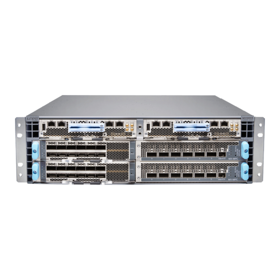
The Juniper Networks MX10003 Universal Routing Platform is an Ethernet-optimized edge router with 2.4Tb capacity that provide both switching and carrier-class Ethernet routing. The MX10003 router runs Junos operating system (Junos OS), enabling a wide range of business and residential applications and services, including high-speed transport and virtual private network (VPN) services, next-generation broadband multiplay services, and high-volume Internet data center internetworking. -
Page 20: Mx10003 Router Hardware Overview
Packet Forwarding Engine takes care of both ingress and egress packet forwarding. The MX10003 is a compact router, three rack units (3U) tall. Several routers can be stacked in a single floor-to-ceiling rack for increased port density per unit of floor space. -
Page 21: Mx10003 Hardware Components And Cli Terminology
NOTE: For a complete list of supported optics on MX10003, see MX10003 Transceivers. SEE ALSO MX10003 Cooling System Description | 31 MX10003 AC Power System Description | 35 MX10003 Router Physical Specifications | 64 MX10003 Hardware Components and CLI Terminology... - Page 22 Table 4: MX10003 Router Hardware Components and CLI Terminology (continued) Hardware Model Component Number CLI Name Description Routing and Control JNP10003-RE1 RE: RE-S-1600x8 “MX10003 Routing and Control Board (RCB) Board (RCB) Description” on JNP10003-RE1-LT CB: Control Board page 47 Transceiver...
-
Page 23: Mx10003 Component Redundancy
Table 5: MX10003 Spare Parts and Blank Panels (continued) Model Number Description JNP-MIC-BLNK-3 MX10003 MIC1 blank cover panel MX10003 Component Redundancy A fully configured router is designed so that no single point of failure can cause the entire system to fail. -
Page 24: Mx10003 Field-Replaceable Units
SEE ALSO Locating the Serial Number on a MX10003 Router or Component | 165 Guidelines for Packing Hardware Components for Shipment | 170 How to Return a Hardware Component to Juniper Networks, Inc. -
Page 25: Mx10003 Chassis
MX10003 Front and Rear Panel Components | 27 MX10003 Cable Management Bracket Description | 28 Alarm LEDs on the MX10003 Front Panel | 29 MX10003 Chassis Description The router chassis is a rigid sheet metal structure that houses all the other router components. - Page 26 The router comes in two variants–AC-powered and DC-powered. Figure 2 on page 26 Figure 3 on page 27 shows the rear of the fully configured chassis. Figure 2: Rear View of the AC-Powered MX10003 Router Power supply modules (AC) Fan modules —...
-
Page 27: Mx10003 Front And Rear Panel Components
Figure 3: Rear View of the DC-Powered MX10003 Router Power supply modules (DC) Fan modules — — Figure 4 on page 27 shows the electrostatic discharge (ESD) point on the router. CAUTION: Before removing or installing components, attach an ESD strap to an ESD point, and place the other end of the strap around your bare wrist. -
Page 28: Front Panel Components
Front Panel Components Table 8 on page 28 lists the components on the front panel of the MX10003 router. Table 8: Front Panel Components in a Fully Configured MX10003 Router Component Slots Number of FRUs 0 and 1 0 and 1... -
Page 29: Alarm Leds On The Mx10003 Front Panel
SEE ALSO Replacing the MX10003 Air Filter Unit | 117 Installing the MX10003 Router in a Rack | 89 Alarm LEDs on the MX10003 Front Panel One alarm LED located on the front panel of the RCB. A red light indicates a critical condition that can result in a system shutdown, and a yellow light indicates a less severe condition that requires monitoring or maintenance. -
Page 30: Mx10003 Cooling System
NOTE: Only the master RCB drives the LED to show the status of the chassis. Table 10: Alarm LEDs on the MX10003 Front Panel Shape Color Description Critical alarm LED—Indicates a critical condition that can cause the router to stop functioning. -
Page 31: Mx10003 Cooling System Description
MX10003 Cooling System Description IN THIS SECTION Fan Modules | 31 Airflow | 33 Air Filter Unit | 33 Power Supply Cooling System | 34 The cooling system components work together to keep all router components within the acceptable temperature range. - Page 32 Figure 7: Fan Module Captive screw Status LED — — Latch —...
-
Page 33: Airflow
Airflow The router has front-to-back (AIR OUT) cooling system (see Figure 8 on page 33). Air is pulled through the front the chassis toward the fan module, which exhausts the air out of the router. Figure 8: Airflow Through the Router Air Filter Unit The air filter unit consists of three parts–the outer filter cover, the air filter, and the inner cage that form the body, and the air filter (see... -
Page 34: Power Supply Cooling System
The exhaust for the power supplies are also located on the rear of the chassis. SEE ALSO Replacing the MX10003 Air Filter Unit | 117 Replacing the MX10003 Air Filter | 119 MX10003 Fan Module LED Each fan module contains one bicolor LED. -
Page 35: Mx10003 Ac Power System
MX10003 AC Power Supply Module LEDs | 36 MX10003 Router AC Power Specifications | 37 AC Power Circuit Breaker Requirements for the MX10003 Router | 38 AC Power Cord Specifications for MX10003 Routers | 39 MX10003 AC Power System Description... -
Page 36: Mx10003 Ac Power Supply Module Leds
This separate protective earthing terminal must be permanently connected to earth. Figure 10: AC Power Supply MX10003 AC Power Supply Module LEDs Figure 11 on page 37 shows the AC power supplies components along with the status LED. -
Page 37: Mx10003 Router Ac Power Specifications
AC inlet plug Handle — — SEE ALSO Routine Maintenance Procedures for MX10003 Routers | 116 MX10003 Router AC Power Specifications Table 12 on page 37 lists the AC power system electrical specifications. Table 12: AC Power System Electrical Specifications... -
Page 38: Ac Power Circuit Breaker Requirements For The Mx10003 Router
General Electrical Safety Guidelines and Warnings | 206 Prevention of Electrostatic Discharge Damage | 182 AC Power Circuit Breaker Requirements for the MX10003 Router We recommend that you use a dedicated customer-site circuit breaker rated for 15 A (110 VAC) minimum or 10 A (220 VAC) minimum for each AC power feed, or as required by local code. -
Page 39: Ac Power Cord Specifications For Mx10003 Routers
General Electrical Safety Guidelines and Warnings | 206 Prevention of Electrostatic Discharge Damage | 182 AC Power Cord Specifications for MX10003 Routers A detachable AC power cord is supplied with the AC power supplies. The coupler is type C13 as described by International Electrotechnical Commission (IEC) standard 60320. - Page 40 Table 14: AC Power Cord Specifications (continued) Country/Region Electrical Specifications Plug Standards Juniper Model Number Italy 250 VAC, 10 A, 50 Hz CEI 23-16 Type I/3G CBL-EX-PWR-C13-IT Japan 125 VAC, 12 A, 50 Hz or 60 SS-00259 Type VCTF CBL-EX-PWR-C13-JP...
-
Page 41: Mx10003 Dc Power System
MX10003 DC Power Supply Module LEDs | 42 MX10003 Router DC Power Specifications | 43 DC Power Circuit Breaker Requirements for the MX10003 Router | 44 DC Power Source Cabling for MX10003 Router | 44 DC Power Cable Specifications for MX10003 Router | 45... -
Page 42: Mx10003 Dc Power Supply Module Leds
Figure 13 on page 42 shows the power supply. Figure 13: DC Power Supply MX10003 DC Power Supply Module LEDs Figure 14 on page 42 shows the DC power supplies components along with the status LED. Figure 14: DC Power Supplies Components... -
Page 43: Mx10003 Router Dc Power Specifications
Operating range: –40 through –72 VDC DC input current rating 32 A @ –48 VDC SEE ALSO Routine Maintenance Procedures for MX10003 Routers | 116 Replacing an MX10003 DC Power Supply | 130 MX10003 Power Planning | 70 General Safety Guidelines and Warnings | 177... -
Page 44: Dc Power Circuit Breaker Requirements For The Mx10003 Router
DC Power Circuit Breaker Requirements for the MX10003 Router Each DC power supply has a single DC input (–48 VDC and return) that requires a dedicated circuit breaker. We recommend that you use a dedicated customer-site circuit breaker rated for 40 A (–48 VDC) minimum, or as required by local code. -
Page 45: Dc Power Cable Specifications For Mx10003 Router
Power cords and cables must not block access to device components or drape where people could trip on them. SEE ALSO Routine Maintenance Procedures for MX10003 Routers | 116 Replacing an MX10003 DC Power Supply | 130 MX10003 Power Planning | 70... -
Page 46: Dc Power Cable Specifications
), minimum 60° C wire, or as required by the local code. SEE ALSO Routine Maintenance Procedures for MX10003 Routers | 116 Replacing an MX10003 DC Power Supply | 130 MX10003 Power Planning | 70 General Safety Guidelines and Warnings | 177... -
Page 47: Mx10003 Routing And Control Board
These routing processes run on top of a kernel that interacts with the Packet Forwarding Engine. The MX10003 host subsystem consists of two Routing and Control Boards, or RCBs. The RCB is an integrated board and a single FRU that provides Routing Engine (RE) and Control Board (CB) functionality. -
Page 48: Routing And Control Board Functions
Each RCB consists of the following internal components: High-performance 1.6-GHz Intel 8 Core X86 CPU 64-GB DDR4 RAM 100-GB SATA SSD RCB Front Panel Figure 16 on page 49 shows the front panel of the MX10003 RCB (model number: JNP10003-RE1). - Page 49 SSD slots (0 and 1) ONLINE LED — — Master (MST) LED OK/FAIL LED — — Alarm (ALM) LED RESET button — — Figure 17 on page 50 shows the front panel of the MX10003 RCB with limited encryption support (model number: JNP10003-RE1-LT).
-
Page 50: Rcb Interface Ports
— — The MX10003 router with JNP10003-RE1-LT RCB supports only Junos Limited image. The Junos Limited image does not have data-plane encryption and is intended only for countries in the Eurasian Customs Union because these countries have import restrictions on software containing data-plane encryption. -
Page 51: Mx10003 Rcb Leds
OS supports USB version 1.0 and later. SEE ALSO Replacing an MX10003 RCB | 136 RJ-45 Connector Pinouts for MX Series CB-RE or RCB Auxillary and Console Ports | 79 RJ-45 Connector Pinouts for an MX Series CB-RE or RCB Management Port | 80... - Page 52 NOTE: The functioning of the MX10003 router is contolled by the RCB, and the LEDs present on the RCBs displays the status and functioning of the MX10003 chassis. Table 17: MX10003 RCB LEDs Label Color State Description ONLINE Green Blinking RCB is starting Junos OS.
-
Page 53: Mx10003 Interface Modules
Supported Routing Engines by Router MX10003 Interface Modules IN THIS SECTION MX10003 MPC (Multi-Rate) | 53 MX10003 Port and Interface Numbering | 55 MX10003 MPC (Multi-Rate) LEDs | 56 Multi-Rate Ethernet MIC LEDs | 57 MX10003 MPC (Multi-Rate) Software release Junos OS release 17.3R1 and later... - Page 54 Hardware features The MX10003 MPC is a 1.2-Terabit capable MPC with three Packet Forwarding Engine complexes (that is, three EA ASICs). The EA ASIC operates in 400G mode. The Packet Forwarding Engine is based on the third generation of the Trio chpiset architecture---namely, the EA (Eagle) ASIC.
-
Page 55: Mx10003 Port And Interface Numbering
40 Gigabit Ethernet 4X10-Gigabit Ethernet SEE ALSO MPC and MIC Lane LED Scheme Overview Configuring Rate Selectability on MX10003 MPC to Enable Different Port Speeds MX10003 MPC Rate-Selectability Overview Interface Naming Conventions for MX10003 MPC Understanding Rate Selectability MX Series MPC Overview... -
Page 56: Mx10003 Mpc (Multi-Rate) Leds
SEE ALSO Interface Naming Conventions for MX10003 MPC MX10003 MPC (Multi-Rate) LEDs The MX10003 MPC (Multi-Rate) has LEDs located on the front panel. Table 19 on page 56 describes the link LEDs in more detail. Table 19: MX10003 MPC (Multi-Rate) LEDs... -
Page 57: Multi-Rate Ethernet Mic Leds
MIC Lane LED Scheme Overview for more details. SEE ALSO MPC and MIC Lane LED Scheme Overview Configuring Rate Selectability on MX10003 MPC to Enable Different Port Speeds MX10003 MPC Rate-Selectability Overview Understanding Rate Selectability MICs Supported by MX Series Routers... -
Page 58: Site Planning, Preparation, And Specifications
Site Planning, Preparation, and Specifications MX10003 Site Preparation Checklist | 59 MX10003 Site Guidelines and Requirements | 60 MX10003 Power Planning | 70 MX10003 Network Cable and Transceiver Planning | 74 MX10003 Management and Console Port Specifications and Pinouts | 79... -
Page 59: Mx10003 Site Preparation Checklist
“MX10003 Router Rack Requirements” on page 66 “MX10003 Router Cabinet Requirements and Specifications” on page 68 Plan rack or cabinet location, including “MX10003 Router Clearance Requirements for Airflow and Hardware Maintenance” on required space clearances. If a rack is used, secure rack to floor and “MX10003 Router Rack Requirements”... -
Page 60: Mx10003 Site Guidelines And Requirements
RELATED DOCUMENTATION MX10003 Installation Overview | 83 Tools Required to the Install MX10003 Router in a Rack | 88 Installing the MX10003 Router in a Rack | 89 MX10003 Site Guidelines and Requirements IN THIS SECTION... -
Page 61: Mx10003 Router Grounding Specifications
Articles 110-16, 110-17, and 110-18 of the National Electrical Code, ANSI/NFPA 70. SEE ALSO Routine Maintenance Procedures for MX10003 Routers | 116 General Safety Guidelines for Juniper Networks Devices General Safety Warnings for Juniper Networks Devices | 178... -
Page 62: Grounding Cable Lug Specifications
routers, you must connect a grounding cable to earth ground and then attach it to the chassis grounding points by using the two screws provided. Figure 18 on page 62 shows the grounding point location on the router. A protective earthing terminal bracket is required for connecting the chassis to earth ground. This two-holed bracket attaches on the side of the chassis through the mounting rail and provides a protective earthing terminal for the switch. -
Page 63: Grounding Cable Specifications
14–10 AWG (2–5.3 mm²) stranded wire, 60° C wire, or as permitted by local code. SEE ALSO Tools and Parts Required for MX10003 Router Grounding and Power Connections | 92 MX10003 Router AC Power Specifications | 37 MX10003 Router DC Power Specifications | 43... -
Page 64: Mx10003 Router Physical Specifications
Figure 19: MX10003 Chassis Dimensions and Clearance Requirements MX10003 Router Physical Specifications Table 23 on page 64 summarizes the physical specifications for the router. Table 23: Router Physical Specifications Description Weight Width Depth Height Chassis fully loaded with AC-powered 19 in. (48.26 cm) 36.5 in. - Page 65 For router maintenance and to accommodate power cable bend radius, allow at least 30 in. (76.2 cm) in front of the rack and 24 in. (61 cm) behind the router (see “MX10003 Router Clearance Requirements for Airflow and Hardware Maintenance” on page 63). SEE ALSO MX10003 Router Hardware Overview | 20...
-
Page 66: Mx10003 Router Rack Requirements
MX10003 Chassis Description | 25 MX10003 Router Rack Requirements The router can be installed in a standard 19-in. rack. Many types of racks are acceptable, including four-post (telco) racks and open-frame racks. Table 24 on page 66 summarizes rack requirements and specifications for the router. - Page 67 If earthquakes are a possibility in your geographic area, secure the rack to the floor. Secure the rack to the ceiling brackets as well as wall or floor brackets for maximum stability. SEE ALSO MX10003 Installation Overview | 83 Installing the MX10003 Router in a Rack | 89...
-
Page 68: Mx10003 Router Cabinet Requirements And Specifications
Components Industry Association (ECIA) (http://www.ecianow.org). With adequate cooling air and airflow clearance, you can stack multiple MX10003 routers in a cabinet with a four-post rack. In all cases, the rack must meet the strength requirements to support the weight. The minimum total clearance inside the cabinet is 30.7 in. (780 mm) between... - Page 69 Table 25: Cabinet Requirements and Specifications for an MX10003 Router (continued) Cabinet Requirement Guidelines for the MX10003 Router Cabinet airflow requirements When you install the router in a cabinet, you must ensure that ventilation through the cabinet is sufficient to prevent overheating. Consider the following requirements to when planning for chassis cooling: Airflow must always be from front to back with respect to the rack.
-
Page 70: Mx10003 Power Planning
MX10003 Installation Overview | 83 MX10003 Power Planning IN THIS SECTION Calculating Power Requirements for MX10003 Router | 70 Calculating Power Requirements for MX10003 Router Use the information in this topic to determine the power consumption for your router and plan the amount of power you need to provide to the router. -
Page 71: Power Requirements For Mx10003 Components
Power Requirements for MX10003 Components Table 26 on page 71 lists the power requirements for various hardware components when the router is operating under typical and maximum voltage conditions. Table 26: Power Requirements for MX10003 Components Power Requirement at Power Requirement 25°... - Page 72 2180 W / 0.9 = 2422 W Table 27 on page 72 lists the power requirements for the fully configured routers operating under typical voltage conditions. Table 27: MX10003 Router Power Requirements at Typical Temperature (25° C) Power Requirement Power Requirement at 25° (Watts) with 90%...
-
Page 73: Calculating System Thermal Output
Table 28: MX10003 Router Power Requirements at Maximum Temperature (55° C) Power Requirement Power Requirement at 55° (Watts) with 90% Fixed Chassis Configuration C (Watts) Efficiency Fully configured chassis running at high activity, 2110 W 2344 W with QSFP28 optics and JNP-MIC1... -
Page 74: Mx10003 Network Cable And Transceiver Planning
Replacing an MX10003 AC Power Supply | 127 AC Power Cord Specifications for MX10003 Routers | 39 AC Power Circuit Breaker Requirements for the MX10003 Router | 38 General Safety Guidelines and Warnings | 177 General Electrical Safety Guidelines and Warnings | 206... -
Page 75: How To Calculate Power Budget For Fiber-Optic Cable
How to Calculate Power Budget for Fiber-Optic Cable To ensure that fiber-optic connections have sufficient power for correct operation, you need to calculate the link's power budget, which is the maximum amount of power it can transmit. When you calculate the power budget, you use a worst-case analysis to provide a margin of error, even though all the parts of an actual system do not operate at the worst-case levels. - Page 76 Table 30: Estimated Values for Factors Causing Link Loss (continued) Link-Loss Factor Estimated Link-Loss Value Connector 0.5 dB Splice 0.5 dB Fiber attenuation Single mode—0.5 dB/km Multimode—1 dB/km The following sample calculation for a 2-km-long multimode link with a power budget (P ) of 13 dB uses the estimated values from Table 30 on page 75...
-
Page 77: Cb-Re And Rcb Interface Cable And Wire Specifications For Mx Series Routers
CB-RE and RCB Interface Cable and Wire Specifications for MX Series Routers Table 31 on page 77 lists the specifications for the cables that connect to management ports and the wires that connect to the alarm relay contacts. NOTE: In routers where the Routing Engine (RE) and Control Board (CB) are integrated into a single board, a CB-RE is known as Routing and Control Board (RCB). -
Page 78: Fiber-Optic Cable Signal Loss, Attenuation, And Dispersion
Fiber-Optic Cable Signal Loss, Attenuation, and Dispersion IN THIS SECTION Signal Loss in Multimode and Single-Mode Fiber-Optic Cable | 78 Attenuation and Dispersion in Fiber-Optic Cable | 78 Signal Loss in Multimode and Single-Mode Fiber-Optic Cable Multimode fiber is large enough in diameter to allow rays of light to reflect internally (bounce off the walls of the fiber). -
Page 79: Mx10003 Management And Console Port Specifications And Pinouts
When chromatic dispersion is at the maximum allowed, its effect can be considered as a power penalty in the power budget. The optical power budget must allow for the sum of component attenuation, power penalties (including those from dispersion), and a safety margin for unexpected losses. MX10003 Management and Console Port Specifications and Pinouts IN THIS SECTION... -
Page 80: Connector Pinouts For An Mx Series Cb-Re Or Rcb Management Port
Table 32: RJ-45 Connector Pinout for the AUX and CONSOLE Ports Signal Description Request to Send Data Terminal Ready Transmit Data Ground Signal Ground Ground Signal Ground Receive Data DSR/DCD Data Set Ready Clear to Send RJ-45 Connector Pinouts for an MX Series CB-RE or RCB Management Port The port on the Control Board and Routing Engine (CB-RE;... - Page 81 Table 33: RJ-45 Management Port Connector Pinouts for the CB-RE or RCB MGMT Port (continued) Signal Description TRP1– Transmit/receive data pair 1 TRP2+ Transmit/receive data pair 2 TRP3+ Transmit/receive data pair 3 TRP3– Transmit/receive data pair 3 TRP2– Transmit/receive data pair 2 TRP4+ Transmit/receive data pair 4 TRP4–...
-
Page 82: Initial Installation And Configuration
C HAPTER Initial Installation and Configuration MX10003 Installation Overview | 83 Tools and Parts Required to Unpack the MX10003 Router | 84 Unpacking the MX10003 Router | 85 Verifying the MX10003 Router Parts Received | 86 Installing the MX10003 | 88... -
Page 83: Mx10003 Installation Overview
See “Verifying the MX10003 Router Parts Received” on page 4. (Optional) Remove components from the MX10003 router chassis before Installing it in a rack. See individual topics listed in Removing, Installing, and Upgrading Components for removing components. 5. Install the router onto the rack. -
Page 84: Tools And Parts Required To Unpack The Mx10003 Router
“Initially Configuring the MX10003 Router” on page 110. RELATED DOCUMENTATION MX10003 Router Rack Requirements | 66 MX10003 Router Clearance Requirements for Airflow and Hardware Maintenance | 63 MX10003 Router Cabinet Requirements and Specifications | 68 Tools and Parts Required to Unpack the MX10003 Router... -
Page 85: Unpacking The Mx10003 Router
7. Save the shipping carton and packing materials in case you later need to move or ship the router. RELATED DOCUMENTATION MX10003 Site Preparation Checklist | 59 Tools and Parts Required to Unpack the MX10003 Router | 84 Verifying the MX10003 Router Parts Received | 86... -
Page 86: Verifying The Mx10003 Router Parts Received
Verifying the MX10003 Router Parts Received A packing list is included in each shipment. Check the parts in the shipment against the items on the packing list. The packing list specifies the part numbers and descriptions of each part in your order. - Page 87 Ethernet cable, RJ-45 to DB-9 ESD wrist strap with cable RELATED DOCUMENTATION MX10003 Site Preparation Checklist | 59 MX10003 Installation Overview | 83 Tools and Parts Required to Unpack the MX10003 Router | 84 Unpacking the MX10003 Router | 85...
-
Page 88: Installing The Mx10003
Installing the MX10003 IN THIS SECTION Tools Required to the Install MX10003 Router in a Rack | 88 Installing the MX10003 Router in a Rack | 89 Tools Required to the Install MX10003 Router in a Rack To install the router, you need the following tools and parts:... -
Page 89: Installing The Mx10003 Router In A Rack
Installing the MX10003 Router in a Rack To install the router in a four-post rack or a cabinet: CAUTION: If you are installing more than one router in a rack, install the lowest one first. Installing a router in an upper position in a rack or cabinet requires a lift. - Page 90 Figure 21: Removing the Rear-Mounting Brackets 4. Install the cable management brackets on each side of the front of the chassis, and secure each bracket with screws at the bottom and top of the bracket (see Figure 22 on page 90).
- Page 91 Figure 24 on page 91 shows the router fully secured and installed in a four-post rack. Figure 24: Router Installed in the Rack 11. Install the air filter unit. See “Replacing the MX10003 Air Filter Unit” on page 117.
-
Page 92: Connecting The Mx10003 To Power
Prevention of Electrostatic Discharge Damage | 182 Connecting the MX10003 to Power IN THIS SECTION Tools and Parts Required for MX10003 Router Grounding and Power Connections | 92 Grounding the MX10003 Router | 94 Connecting Power to an AC-Powered MX10003 Router | 95... - Page 93 Wire cutters Electrostatic discharge (ESD) grounding wrist strap SEE ALSO MX10003 Router Grounding Specifications | 61 General Safety Guidelines and Warnings | 177 General Electrical Safety Guidelines and Warnings | 206 Prevention of Electrostatic Discharge Damage | 182...
-
Page 94: Grounding The Mx10003 Router
You must provide the grounding cables (the cable lugs are supplied with the router). For grounding cable specifications, see “MX10003 Router Grounding Specifications” on page Figure 25: Grounding Points on the MX10003 Router Grounding point —... -
Page 95: Connecting Power To An Ac-Powered Mx10003 Router
9. Dress the grounding cable, and verify that it does not touch or block access to router components, and that it does not drape where people could trip on it. Figure 26: Connecting Grounding lugs to the MX10003 Router SEE ALSO... - Page 96 1. Locate power cords that have a plug appropriate for your geographic location. For more information, “AC Power Cord Specifications for MX10003 Routers” on page 2. Attach an ESD grounding strap to your bare wrist and connect the strap to one of the ESD points on the chassis.
-
Page 97: Connecting Power To A Dc-Powered Mx10003 Router
General Safety Guidelines and Warnings | 177 General Electrical Safety Guidelines and Warnings | 206 Prevention of Electrostatic Discharge Damage | 182 Connecting Power to a DC-Powered MX10003 Router CAUTION: Do not mix AC and DC power supply modules within the same router. - Page 98 To connect the DC source power cables to the router for each power supply: 1. Switch off the dedicated customer-site circuit breakers. Ensure that the voltage across the DC power source cable leads is 0 V and that there is no chance that the cable leads might become active during installation.
- Page 99 7. Repeat Step 1 through Step 6 for installing the other power supplies. Figure 28: Connecting DC Power to the Router SEE ALSO MX10003 Router Grounding Specifications | 61 General Safety Guidelines and Warnings | 177 General Electrical Safety Guidelines and Warnings | 206...
-
Page 100: Connecting The Mx10003 To The Network
Connecting the MX10003 to the Network IN THIS SECTION Tools and Parts Required to Connect the MX10003 Router to External Devices | 100 Connecting the MX10003 Router to External Devices and Cables | 100 Tools and Parts Required to Connect the MX10003 Router to External... -
Page 101: Connecting The Router To A Network For Out-Of-Band Management
Figure 29 on page 101 shows the front panel of the MX10003 RCB. All the connections to the router are made through the RCBs. The external devices are connected through the RCBs. Figure 29: Routing and Control Board (RCB) Ports... -
Page 102: Connecting The Router To A Console Device
Figure 30: Out-of-Band Management Cable Connector Table 36: Out-of-Band Management Port on the RCB Callout (see Figure 29 on page 101) Label Description MGMT Dedicated management channel for device maintenance. It is also used by system administrators to monitor and manage the router remotely. - Page 103 NOTE: For console devices, configure the serial port to the following values: Baud rate—9600 Parity—N Data bits—8 Stop bits—1 Flow control—none Figure 31: Console and Auxiliary Cable Connector Figure 32: Connecting a router to a Management Console Through a Console Server To Console Port Console Server Figure 33: Connecting a router Directly to a Management Console...
-
Page 104: Connecting The Router To External Clocking And Timing Devices
10-MHz-OUT timing ports. NOTE: MX10003 can be configured as a timing master or a slave device. If the MX10003 is configured as a timing master device, the router gets 1-PPS-IN and 10-MHz-IN input (connected to the ports marked IN) from the timing source and sends 1-PPS-OUT and 10-MHz-OUT to a slave device. - Page 105 Table 38: Clocking Port on the RCB Callout (see Figure 29 on page 101) Label Description 10MHz- IN 1 PPS input port 1PPS-IN 10 MHz input port 10MHz-OUT 1 PPS output port 1PPS-OUT 10 MHz output port Connecting a Time-of-Day Device to the Router A time-of-day port labeled ToD on the front panel of the RCB enables you to connect external timing devices.
-
Page 106: Powering On And Off The Mx10003
BITS Building-Integrated Timing Supply (BITS) clock interface port. SEE ALSO MX10003 Routing and Control Board (RCB) Description | 47 Prevention of Electrostatic Discharge Damage | 182 Powering On and Off the MX10003 IN THIS SECTION Powering On an AC-Powered MX10003 Router | 107... -
Page 107: Powering On An Ac-Powered Mx10003 Router
Powering On an AC-Powered MX10003 Router To power on an AC-powered router: 1. Verify that the power supplies are fully inserted in the chassis. 2. Verify that each AC power cord is securely inserted into its appliance inlet. 3. Verify that an external management device is connected to one of the RCB ports (CON). -
Page 108: Powering On A Dc-Powered Mx10003 Router
SEE ALSO MX10003 Router Grounding Specifications | 61 request system halt show chassis power General Safety Guidelines and Warnings | 177 General Electrical Safety Guidelines and Warnings | 206 Prevention of Electrostatic Discharge Damage | 182 Powering On a DC-Powered MX10003 Router To power on a DC-powered router: 1. - Page 109 10. On the external management device connected to the RCB, monitor the startup process to verify that the system has booted properly. SEE ALSO MX10003 Router Grounding Specifications | 61 request system halt show chassis power General Safety Guidelines and Warnings | 177...
-
Page 110: Powering Off The Mx10003 Router
Powering Off the MX10003 Router NOTE: After powering off a power supply, wait at least 60 seconds before turning it back on. To power off the router: 1. On the external management device connected to the RCB, issue the request system halt command. - Page 111 Gather the following information before configuring the router: Name the router will use on the network Domain name the router will use IP address and prefix length information for the Ethernet interface IP address of a default router IP address of a DNS server Password for the root user This procedure connects the router to the network but does not enable it to forward traffic.
- Page 112 root@# set system login user user-name authentication plain-text-password New password: password Retype new password: password 7. Set the user account class to super-user. [edit] root@# set system login user user-name class super-user 8. Configure the router’s domain name. [edit] root@# set system domain-name domain-name 9.
- Page 113 [edit] root@# set system root-authentication encrypted-password encrypted-password [edit] root@# set system root-authentication ssh-dsa public-key [edit] root@# set system root-authentication ssh-rsa public-key 13. (Optional) Configure the static routes to remote subnets with access to the management port. Access to the management port is limited to the local subnet. To access the management port from a remote subnet, you need to add a static route to that subnet within the routing table.
- Page 114 interfaces { fxp0 { unit 0 { family inet { address address/prefix-length; 16. Commit the configuration to activate it on the router. [edit] root@# commit 17. (Optional) Configure additional properties by adding the necessary configuration statements. Then commit the changes to activate them on the router. [edit] root@host# commit 18.
-
Page 115: Maintaining Components
C HAPTER Maintaining Components Routine Maintenance Procedures for MX10003 Routers | 116 Maintaining MX10003 Cooling System Components | 116 Maintaining MX10003 Power System Components | 126 Maintaining MX10003 Routing and Control Board | 134 Maintaining MX10003 Interface Modules | 140... -
Page 116: Routine Maintenance Procedures For Mx10003 Routers
Check the status-reporting devices on the font panel—system alarms and LEDs. RELATED DOCUMENTATION Alarm LEDs on the MX10003 Front Panel | 29 Maintaining MX10003 Cooling System Components IN THIS SECTION... -
Page 117: Replacing The Mx10003 Air Filter Unit
Replacing the MX10003 Air Filter Unit IN THIS SECTION Removing the MX10003 Air Filter Unit | 118 Installing the MX10003 Air Filter Unit | 118 The air filter unit consists of three parts–the outer filter cover, the air filter, and the inner cage which forms the body, and the air filter. -
Page 118: Removing The Mx10003 Air Filter Unit
Removing the MX10003 Air Filter Unit NOTE: Air filter assembly is designed to prevent dust from being drawn into the chassis. This filter assembly must be installed for the product to be NEBS GR 63 compliant. To remove the air filter unit: 1. -
Page 119: Replacing The Mx10003 Air Filter
4. Tighten the captive screws to secure the air filter unit. SEE ALSO MX10003 Cooling System Description | 31 Prevention of Electrostatic Discharge Damage | 182 Replacing the MX10003 Air Filter IN THIS SECTION Removing the MX10003 Air Filter | 120 Installing the MX10003 Air Filter | 121... -
Page 120: Removing The Mx10003 Air Filter
Regularly inspect the air filter. A dirty air filter restricts airflow in the unit, producing a negative effect on the ventilation of the chassis. Removing the MX10003 Air Filter CAUTION: Do not run the router for more than a few minutes without the air filter in place. -
Page 121: Installing The Mx10003 Air Filter
— Air filter — Installing the MX10003 Air Filter NOTE: The air filter unit is installed on the cable management brackets. Before installing the air filter unit, ensure that the cable management brackets are already installed on the front of the router. -
Page 122: Maintaining The Mx10003 Fan Module
Air filter — 5. Place the outer air filter cover back into it’s place, and tighten the captive screws to secure the air filter unit. Maintaining the MX10003 Fan Module Purpose For optimum cooling, verify the condition of the fans. Action Monitor the status of the fans. -
Page 123: Replacing An Mx10003 Fan Module
Fan Tray 2 Fan 0 Spinning at normal speed Fan Tray 2 Fan 1 Spinning at normal speed Replacing an MX10003 Fan Module IN THIS SECTION Removing an MX10003 Fan Module | 124 Installing an MX10003 Fan Module | 125... -
Page 124: Removing An Mx10003 Fan Module
Removing an MX10003 Fan Module NOTE: To prevent overheating, install the replacement fan module immediately after removing the existing fan module. To remove the fan module (see Figure 38 on page 124): 1. Attach an ESD grounding strap to your bare wrist and connect the strap to one of the ESD points on the chassis. -
Page 125: Installing An Mx10003 Fan Module
4. Using a number-2 Phillips screwdriver, turn the locking screw on the fan module faceplate until it is tight and secured. Figure 39: Installing the Fan Module SEE ALSO MX10003 Cooling System Description | 31 Prevention of Electrostatic Discharge Damage | 182... -
Page 126: Maintaining Mx10003 Power System Components
Maintaining MX10003 Power System Components IN THIS SECTION Maintaining the Power Supplies | 126 Replacing an MX10003 AC Power Supply | 127 Replacing an MX10003 DC Power Supply | 130 Maintaining the Power Supplies Purpose For optimum router performance, verify the condition of the power supplies. -
Page 127: Replacing An Mx10003 Ac Power Supply
Do not mix AC and DC power supplies in the same chassis. SEE ALSO MX10003 AC Power System Description | 35 MX10003 AC Power Supply Module LEDs | 36 Replacing an MX10003 AC Power Supply IN THIS SECTION Removing an MX10003 AC Power Supply | 127... - Page 128 CAUTION: To maintain proper cooling and prevent thermal shutdown of the operating power supply unit, each power supply slot must contain either a power supply or a blank panel. If you remove a power supply, you must install a replacement power supply or a blank panel shortly after the removal.
-
Page 129: Installing An Mx10003 Ac Power Supply
Figure 41: Installing an AC Power Supply SEE ALSO MX10003 AC Power System Description | 35 MX10003 Router AC Power Specifications | 37 AC Power Circuit Breaker Requirements for the MX10003 Router | 38 AC Power Cord Specifications for MX10003 Routers | 39... -
Page 130: Replacing An Mx10003 Dc Power Supply
Prevention of Electrostatic Discharge Damage | 182 Replacing an MX10003 DC Power Supply IN THIS SECTION Removing an MX10003 DC Power Supply | 130 Installing an MX10003 DC Power Supply | 132 Removing an MX10003 DC Power Supply Before you remove a power supply, be aware of the following:... - Page 131 To remove a DC power supply: 1. Switch off the dedicated customer-site circuit breaker for the power supply being removed. Follow your site's procedures for ESD. 2. Make sure that the voltage across the DC power source cable leads is 0 V and that there is no chance that the cables might become active during the removal process.
-
Page 132: Installing An Mx10003 Dc Power Supply
Figure 43: Removing a DC Power Supply Installing an MX10003 DC Power Supply WARNING: Before performing DC power procedures, ensure that power is removed from the DC circuit. To ensure that all power is off, locate the circuit breaker on the panel board that services the DC circuit, switch the circuit breaker to the off position, and tape the switch handle of the circuit breaker in the off position. - Page 133 CAUTION: Ensure that each power cable lug seats flush against the surface of the terminal block as you are tightening the screws. Ensure that each screw is properly threaded into the terminal. Applying installation torque to the screw when improperly threaded can result in damage to the terminal. CAUTION: You must ensure that power connections maintain the proper polarity.
-
Page 134: Maintaining Mx10003 Routing And Control Board
MX10003 AC Power System Description | 35 MX10003 Router DC Power Specifications | 43 DC Power Circuit Breaker Requirements for the MX10003 Router | 44 DC Power Source Cabling for MX10003 Router | 44 DC Power Cable Specifications for MX10003 Router | 45... -
Page 135: Maintaining The Routing And Control Board (Rcb)
Maintaining the Routing and Control Board (RCB) Purpose For optimum router performance, verify the condition of the RCB on regular basis. Action On a regular basis: Check the LEDs on the front panel to view information about the status of the RCB. To check the status of the Routing Engine on the RCB, issue the show chassis routing-engine command. -
Page 136: Replacing An Mx10003 Rcb
Routing Engine status: Slot 1: Current state Present SEE ALSO MX10003 Routing and Control Board (RCB) Description | 47 MX10003 RCB LEDs | 51 show chassis routing-engine Replacing an MX10003 RCB IN THIS SECTION Removing an MX10003 RCB | 137... -
Page 137: Removing An Mx10003 Rcb
Removing an MX10003 RCB The MX10003 host subsystem consists of two Routing and Control Boards (RCBs). The RCB is an integrated board and a single FRU that provides Routing Engine and Control Board functionality and supports virtualization. To remove an RCB (see... -
Page 138: Installing An Mx10003 Rcb
Figure 46: Removing a RCB Installing an MX10003 RCB To install an MX10003 RCB (see Figure 47 on page 140): 1. Attach an electrostatic discharge (ESD) grounding strap to your bare wrist, and connect the strap to one of the ESD points on the chassis. - Page 139 Memory utilization 6 percent 5 sec CPU utilization: User 1 percent Background 0 percent Kernel 0 percent Interrupt 0 percent Idle 99 percent 1 min CPU utilization: User 2 percent Background 0 percent Kernel 1 percent Interrupt 0 percent Idle 97 percent 5 min CPU utilization: User...
-
Page 140: Maintaining Mx10003 Interface Modules
Maintaining MICs | 141 Replacing an MX10003 MIC | 141 Maintaining MPCs | 146 Replacing an MX10003 MPC | 148 Maintaining Cables That Connect to MPCs or MICs | 152 Replacing a Cable on an MX10003 MPC or MIC | 154... -
Page 141: Maintaining Mics
LC2103 PIC 0 Online 6xQSFPP PIC 1 Online MIC1 For further description of the output from the command, see the Explorer. Replacing an MX10003 MIC IN THIS SECTION Removing an MX10003 MIC | 142 Installing an MX10003 MIC | 144... -
Page 142: Removing An Mx10003 Mic
MIC interfaces being removed no longer function. NOTE: On the MX10003 MPC (Multi-Rate), only the MIC in slot 1 is removable. The MIC in slot 0 is fixed to the MPC and cannot be removed. The MICs are located in the MPCs installed at the front of the router. A typical MIC weighs around 3 lb (1.36 kg). - Page 143 5. Disconnect the cables from the MIC. If the MIC uses fiber-optic cable, immediately cover each transceiver and the end of each cable with a rubber safety cap. WARNING: Do not look directly into a fiber-optic transceiver or into the ends of fiber-optic cables.
-
Page 144: Installing An Mx10003 Mic
Figure 49: Removing a MIC Installing an MX10003 MIC To install a MIC (see Figure 50 on page 146): 1. Attach an electrostatic discharge (ESD) grounding strap to your bare wrist, and connect the strap to one of the ESD points on the chassis. - Page 145 CAUTION: Do not leave a fiber-optic transceiver uncovered except when inserting or removing cable. The safety cap keeps the port clean and prevents accidental exposure to laser light. 7. Insert the appropriate cables into the cable connectors on the MIC. 8.
-
Page 146: Maintaining Mpcs
Figure 50: Installing a MIC SEE ALSO Routine Maintenance Procedures for MX10003 Routers | 116 Prevention of Electrostatic Discharge Damage | 182 Maintaining MPCs Purpose The router can have up to two MPCs mounted horizontally in the card cage at the front of the chassis. - Page 147 For more detailed output, add the detail option. The following example does not specify a slot number, which is optional: user@host> show chassis fpc detail Slot 0 information: State Online Total CPU DRAM 3136 MB Total RLDRAM 771 MB Total DDR DRAM 18432 MB Temperature 57 degrees C / 134 degrees F...
-
Page 148: Replacing An Mx10003 Mpc
Replacing an MX10003 MPC IN THIS SECTION Removing an MX10003 MPC | 148 Installing an MX10003 MPC | 150 Removing an MX10003 MPC When you remove an MPC, the router continues to function, although the MIC interfaces installed on the MPC being removed no longer function. - Page 149 WARNING: Do not look directly into a fiber-optic transceiver or into the ends of fiber-optic cables. Fiber-optic transceivers and fiber-optic cables connected to a transceiver emit laser light that can damage your eyes. CAUTION: Do not leave a fiber-optic transceiver uncovered except when inserting or removing a cable.
-
Page 150: Installing An Mx10003 Mpc
MPC into a different slot. Figure 51: Removing an MPC Installing an MX10003 MPC An MPC installs horizontally at the front of the router. The MPCs are hot-insertable and hot-removable. A fully configured MPC can weigh up to 18.35 lb (8.3 kg). Be prepared to accept its full weight. - Page 151 7. Orient the MPC so that the faceplate faces you. 8. Lift the MPC into place, and carefully align the sides of the MPC with the guides inside the card cage. CAUTION: When the MPC is out of the chassis, do not hold it by the ejector handles, bus bars, or edge connectors.
-
Page 152: Maintaining Cables That Connect To Mpcs Or Mics
Figure 52: Installing an MPC SEE ALSO Replacing a Cable on an MX10003 MPC or MIC | 154 Routine Maintenance Procedures for MX10003 Routers | 116 Prevention of Electrostatic Discharge Damage | 182 Maintaining Cables That Connect to MPCs or MICs Purpose For optimum router performance, verify the condition of the cables that connect to the MPCs or MICs. - Page 153 On a regular basis: Use the cable management brackets to support cables and prevent cables from dislodging or developing stress points. Place excess cable out of the way in the cable management brackets. Do not allow fastened loops of cable to dangle from the connector or cable management brackets, because this stresses the cable at the fastening point.
-
Page 154: Replacing A Cable On An Mx10003 Mpc Or Mic
Replacing a Cable on an MX10003 MPC or MIC IN THIS SECTION Removing a Cable on an MPC or MIC | 154 Installing a Cable on an MPC or MIC | 155 Removing a Cable on an MPC or MIC Removing and installing cables on an MPC or MIC does not affect router function. -
Page 155: Installing A Cable On An Mpc Or Mic
WARNING: Do not look directly into a fiber-optic transceiver or into the ends of fiber-optic cables. Fiber-optic transceivers and fiber-optic cables connected to a transceiver emit laser light that can damage your eyes. CAUTION: Do not leave a fiber-optic transceiver uncovered except when you are inserting or removing cable. - Page 156 CAUTION: Do not let fiber-optic cables hang free from the connector. Do not allow the fastened loops of a cable to dangle, which stresses the cable at the fastening point. CAUTION: Avoid bending a fiber-optic cable beyond its minimum bend radius. An arc smaller than a few inches in diameter can damage the cable and cause problems that are difficult to diagnose.
-
Page 157: Replace An Sfp, Sfp+, Or Qsfp+ Transceiver
IN THIS SECTION Remove a Transceiver | 157 Install a Transceiver | 158 The transceivers for Juniper Networks devices are hot-removable and hot-insertable field-replaceable units (FRUs). You can remove and replace them without powering off the device or disrupting the device functions. -
Page 158: Install A Transceiver
4. Remove the cable connector from the transceiver. Immediately cover the transceiver and the end of the cable with a rubber safety cap. WARNING: Do not look directly into a fiber-optic transceiver or into the ends of fiber-optic cables. Fiber-optic transceivers and fiber-optic cables connected to a transceiver emit laser light that can damage your eyes. -
Page 159: Replace A Qsfp28 Transceiver
3. Verify that each transceiver is covered by a rubber safety cap. If it is not, cover the transceiver with a safety cap. 4. Carefully align the transceiver with the slots in the component. The connectors should face the component. 5. -
Page 160: Remove A Qsfp28 Transceiver
Remove a QSFP28 Transceiver To remove a QSFP28 transceiver (see Figure 54 on page 161): 1. Place an electrostatic bag or antistatic mat on a flat, stable surface to receive the QSFP28 transceiver. Have ready a rubber safety cap for the QSFP28 transceiver and the cable. 2. -
Page 161: Install A Qsfp28 Transceiver
Figure 54: 28-Gbps Quad Small Form-Factor Pluggable (QSFP28) Transceiver Install a QSFP28 Transceiver To install a replacement QSFP28 transceiver: 1. Wrap and fasten one end of the ESD grounding strap around your bare wrist, and connect the other end of the strap to the ESD point on the chassis. 2. - Page 162 excess cable out of the way in a neatly coiled loop in the cable management system. Placing fasteners on the loop helps to maintain its shape. CAUTION: Do not let the fiber-optic cable hang free from the connector. Do not allow fastened loops of the cable to dangle, which stresses the cable at the fastening point.
-
Page 163: Contacting Customer Support And Returning The Chassis Or Components | 164
C HAPTER Contacting Customer Support and Returning the Chassis or Components Contacting Customer Support and Returning the Chassis or Components | 164... -
Page 164: Contacting Customer Support And Returning The Chassis Or Components
Guidelines for Packing Hardware Components for Shipment | 170 Contact Customer Support to Obtain Return Material Authorization If you are returning a device or hardware component to Juniper Networks for repair or replacement, obtain a Return Material Authorization (RMA) number from Juniper Networks Technical Assistance Center (JTAC). -
Page 165: Locating The Serial Number On A Mx10003 Router Or Component
Locating the Serial Number ID Label on a MX10003 SATA SSD | 170 If you are returning a router or component to Juniper Networks for repair or replacement, you must locate the serial number of the router or component. You must provide the serial number to the Juniper Networks Technical Assistance Center (JTAC) when you contact them to obtain a Return Materials Authorization (RMA). -
Page 166: Listing The Chassis And Component Details Using The Cli
Listing the Chassis and Component Details Using the CLI To list the MX10003 chassis and the components and their serial numbers, use the show chassis hardware CLI operational mode command. user@device> show chassis hardware Hardware inventory: Item Version Part number... -
Page 167: Locating The Serial Number Id Labels On Mx10003 Power Supplies
Locating the Serial Number ID Labels on MX10003 Power Supplies The power supplies installed in a MX10003 are field-replaceable units (FRUs). For each FRU, you must remove the FRU from the router chassis to see the FRU serial number ID label. -
Page 168: Locating The Serial Number Id Label On Mx10003 Fan Module
Figure 58: MX10003 Fan Module Serial Number Location Locating the Serial Number ID Labels on MX10003 Line Cards The serial number ID label for an MX10003 MPC is located on the connector end of the card. See Figure 59 on page... -
Page 169: Locating The Serial Number Id Labels On Mx10003 Routing And Control Board (Rcb)
Figure 59: MX10003 MPC Serial Number Location The serial number ID label for an MX10003 MIC is located on the connector end of the card. See Figure 60 on page 169. Figure 60: MX10003 MIC Serial Number Location Locating the Serial Number ID Labels on MX10003 Routing and Control Board (RCB) The serial number ID label for an MX10003 RCB is located on the connector end of the card. -
Page 170: Locating The Serial Number Id Label On A Mx10003 Sata Ssd
Figure 61: MX10003 RCB Serial Number Location Locating the Serial Number ID Label on a MX10003 SATA SSD The serial number for a SATA SSD is located on top of the drive. See Figure 62 on page 170. Figure 62: MX10003 SATA SSD Serial Number Location... - Page 171 CAUTION: Do not stack any of the hardware components.
-
Page 172: Safety And Compliance Information
Safety and Compliance Information Definitions of Safety Warning Levels | 174 General Safety Guidelines and Warnings | 177 General Safety Warnings for Juniper Networks Devices | 178 Prevention of Electrostatic Discharge Damage | 182 Fire Safety Requirements | 184 Installation Instructions Warning | 185... - Page 173 Agency Approvals for MX10003 Router | 224 Compliance Statements for NEBS | 225 Compliance Statements for EMC Requirements | 225 Compliance Statements for Environmental Requirements | 227 Compliance Statements for Acoustic Noise for MX10003 Router | 227 Statements of Volatility for Juniper Network Devices | 228...
-
Page 174: Definitions Of Safety Warning Levels
Definitions of Safety Warning Levels The documentation uses the following levels of safety warnings (there are two Warning formats): NOTE: You might find this information helpful in a particular situation, or you might overlook this important information if it was not highlighted in a Note. CAUTION: You need to observe the specified guidelines to prevent minor injury or discomfort to you or severe damage to the device. - Page 176 WARNING: This symbol means danger. You are in a situation that could cause bodily injury. Before you work on any equipment, be aware of the hazards involved with electrical circuitry and be familiar with standard practices for preventing accidents. Waarschuwing Dit waarschuwingssymbool betekent gevaar. U verkeert in een situatie die lichamelijk letsel kan veroorzaken.
-
Page 177: General Safety Guidelines And Warnings
Varning! Denna varningssymbol signalerar fara. Du befinner dig i en situation som kan leda till personskada. Innan du utför arbete på någon utrustning måste du vara medveten om farorna med elkretsar och känna till vanligt förfarande för att förebygga skador. General Safety Guidelines and Warnings The following guidelines help ensure your safety and protect the device from damage. -
Page 178: General Safety Warnings For Juniper Networks Devices
Always ensure that all modules, power supplies, and cover panels are fully inserted and that the installation screws are fully tightened. General Safety Warnings for Juniper Networks Devices IN THIS SECTION Qualified Personnel Warning | 179... -
Page 179: Qualified Personnel Warning
Qualified Personnel Warning WARNING: Only trained and qualified personnel should install or replace the hardware equipment. Waarschuwing Installatie en reparaties mogen uitsluitend door getraind en bevoegd personeel uitgevoerd worden. Varoitus Ainoastaan koulutettu ja pätevä henkilökunta saa asentaa tai vaihtaa tämän laitteen. -
Page 180: Restricted-Access Area Warning
Restricted-Access Area Warning... - Page 181 WARNING: The hardware equipment is intended for installation in restricted-access areas. A restricted-access area is an area to which access can be gained only by service personnel through the use of a special tool, lock and key, or other means of security, and which is controlled by the authority responsible for the location.
-
Page 182: Prevention Of Electrostatic Discharge Damage
RELATED DOCUMENTATION Installation Safety Warnings for Juniper Networks Devices Maintenance and Operational Safety Warnings for Juniper Networks Devices General Electrical Safety Warnings for Juniper Networks Devices DC Power Electrical Safety Warnings for Juniper Networks Devices Prevention of Electrostatic Discharge Damage Device components that are shipped in antistatic bags are sensitive to damage from static electricity. - Page 183 Always use an ESD wrist strap when you are handling components that are subject to ESD damage, and make sure that it is in direct contact with your skin. If a grounding strap is not available, hold the component in its antistatic bag (see Figure 63 on page 183) in one hand and touch the exposed, bare metal of the device with the other hand immediately before...
-
Page 184: Fire Safety Requirements
In addition, you should establish procedures to protect your equipment in the event of a fire emergency. Juniper Networks products should be installed in an environment suitable for electronic equipment. We recommend that fire suppression equipment be available in the event of a fire in the vicinity of the equipment and that all local fire, safety, and electrical codes and ordinances be observed when you install and operate your equipment. -
Page 185: Installation Instructions Warning
To keep warranties effective, do not use a dry chemical fire extinguisher to control a fire at or near a Juniper Networks device. If a dry chemical fire extinguisher is used, the unit is no longer eligible for coverage under a service agreement. -
Page 186: Chassis And Component Lifting Guidelines
Chassis and Component Lifting Guidelines Before moving the device to a site, ensure that the site meets the power, environmental, and clearance requirements. Before lifting or moving the device, disconnect all external cables and wires. As when lifting any heavy object, ensure that most of the weight is borne by your legs rather than your back. -
Page 187: Ramp Warning
Ramp Warning WARNING: When installing the device, do not use a ramp inclined at more than 10 degrees. Waarschuwing Gebruik een oprijplaat niet onder een hoek van meer dan 10 graden. Varoitus Älä käytä sellaista kaltevaa pintaa, jonka kaltevuus ylittää 10 astetta. Attention Ne pas utiliser une rampe dont l'inclinaison est supérieure à... - Page 189 De onderstaande richtlijnen worden verstrekt om uw veiligheid te verzekeren: De Juniper Networks switch moet in een stellage worden geïnstalleerd die aan een bouwsel is verankerd. Dit toestel dient onderaan in het rek gemonteerd te worden als het toestel het enige in het rek is.
- Page 190 Les directives ci-dessous sont destinées à assurer la protection du personnel: Le rack sur lequel est monté le Juniper Networks switch doit être fixé à la structure du bâtiment. Si cette unité constitue la seule unité montée en casier, elle doit être placée dans le bas.
- Page 191 Il Juniper Networks switch deve essere installato in un telaio, il quale deve essere fissato alla struttura dell'edificio. Questa unità deve venire montata sul fondo del supporto, se si tratta dell'unica unità da montare nel supporto. Quando questa unità viene montata in un supporto parzialmente pieno, caricare il supporto dal basso all'alto, con il componente più...
-
Page 192: Laser And Led Safety Guidelines And Warnings
El Juniper Networks switch debe instalarse en un bastidor fijado a la estructura del edificio. Colocar el equipo en la parte inferior del bastidor, cuando sea la única unidad en el mismo. Cuando este equipo se vaya a instalar en un bastidor parcialmente ocupado, comenzar la instalación desde la parte inferior hacia la superior colocando el equipo más pesado... -
Page 193: General Laser Safety Guidelines
Juniper Networks devices are equipped with laser transmitters, which are considered a Class 1 Laser Product by the U.S. Food and Drug Administration and are evaluated as a Class 1 Laser Product per EN 60825-1 requirements. Observe the following guidelines and warnings:... -
Page 194: Class 1 Laser Product Warning
Class 1 Laser Product Warning WARNING: Class 1 laser product. Waarschuwing Klasse-1 laser produkt. Varoitus Luokan 1 lasertuote. Attention Produit laser de classe I. Warnung Laserprodukt der Klasse 1. Avvertenza Prodotto laser di Classe 1. Advarsel Laserprodukt av klasse 1. Aviso Produto laser de classe 1. -
Page 195: Class 1 Led Product Warning
Class 1 LED Product Warning WARNING: Class 1 LED product. Waarschuwing Klasse 1 LED-product. Varoitus Luokan 1 valodiodituote. Attention Alarme de produit LED Class I. Warnung Class 1 LED-Produktwarnung. Avvertenza Avvertenza prodotto LED di Classe 1. Advarsel LED-produkt i klasse 1. Aviso Produto de classe 1 com LED. -
Page 196: Laser Beam Warning
Laser Beam Warning WARNING: Do not stare into the laser beam or view it directly with optical instruments. Waarschuwing Niet in de straal staren of hem rechtstreeks bekijken met optische instrumenten. Varoitus Älä katso säteeseen äläkä tarkastele sitä suoraan optisen laitteen avulla. Attention Ne pas fixer le faisceau des yeux, ni l'observer directement à... -
Page 197: Radiation From Open Port Apertures Warning
Radiation from Open Port Apertures Warning WARNING: Because invisible radiation might be emitted from the aperture of the port when no fiber cable is connected, avoid exposure to radiation and do not stare into open apertures. Waarschuwing Aangezien onzichtbare straling vanuit de opening van de poort kan komen als er geen fiberkabel aangesloten is, dient blootstelling aan straling en het kijken in open openingen vermeden te worden. -
Page 198: Maintenance And Operational Safety Guidelines And Warnings
Maintenance and Operational Safety Guidelines and Warnings IN THIS SECTION Battery Handling Warning | 199 Jewelry Removal Warning | 200 Lightning Activity Warning | 202 Operating Temperature Warning | 203 Product Disposal Warning | 205 While performing the maintenance activities for devices, observe the following guidelines and warnings:... -
Page 199: Battery Handling Warning
Battery Handling Warning WARNING: Replacing a battery incorrectly might result in an explosion. Replace a battery only with the same or equivalent type recommended by the manufacturer. Dispose of used batteries according to the manufacturer's instructions. Waarschuwing Er is ontploffingsgevaar als de batterij verkeerd vervangen wordt. Vervang de batterij slechts met hetzelfde of een equivalent type dat door de fabrikant aanbevolen is. -
Page 200: Jewelry Removal Warning
Jewelry Removal Warning... - Page 201 WARNING: Before working on equipment that is connected to power lines, remove jewelry, including rings, necklaces, and watches. Metal objects heat up when connected to power and ground and can cause serious burns or can be welded to the terminals. Waarschuwing Alvorens aan apparatuur te werken die met elektrische leidingen is verbonden, sieraden (inclusief ringen, kettingen en horloges) verwijderen.
-
Page 202: Lightning Activity Warning
se conectan a la alimentación y a tierra, lo que puede ocasionar quemaduras graves o que los objetos metálicos queden soldados a los bornes. Varning! Tag av alla smycken (inklusive ringar, halsband och armbandsur) innan du arbetar på utrustning som är kopplad till kraftledningar. Metallobjekt hettas upp när de kopplas ihop med ström och jord och kan förorsaka allvarliga brännskador;... -
Page 203: Operating Temperature Warning
Operating Temperature Warning... - Page 204 40° C. Para evitar a restrição à circulação de ar, deixe pelo menos um espaço de 15,2 cm à volta das aberturas de ventilação. ¡Atención! Para impedir que un encaminador de la serie Juniper Networks switch se recaliente, no lo haga funcionar en un área en la que se supere la temperatura ambiente máxima recomendada de 40°...
-
Page 205: Product Disposal Warning
Varning! Förhindra att en Juniper Networks switch överhettas genom att inte använda den i ett område där den maximalt rekommenderade omgivningstemperaturen på 40° C överskrids. Förhindra att luftcirkulationen inskränks genom att se till att det finns fritt utrymme på minst 15,2 cm omkring ventilationsöppningarna. -
Page 206: General Electrical Safety Guidelines And Warnings
General Electrical Safety Guidelines and Warnings WARNING: Certain ports on the device are designed for use as intrabuilding (within-the-building) interfaces only (Type 2 or Type 4 ports as described in GR-1089-CORE) and require isolation from the exposed outside plant (OSP) cabling. To comply with NEBS requirements and protect against lightning surges and commercial power disturbances, the intrabuilding ports must not be metallically connected to interfaces that connect to the OSP or its wiring. -
Page 207: Prevention Of Electrostatic Discharge Damage
Carefully look for possible hazards in your work area, such as moist floors, ungrounded power extension cords, and missing safety grounds. Operate the device within marked electrical ratings and product usage instructions. To ensure that the device and peripheral equipment function safely and correctly, use the cables and connectors specified for the attached peripheral equipment, and make certain they are in good condition. -
Page 208: Site Electrical Wiring Guidelines
Figure 64: Placing a Component into an Antistatic Bag CAUTION ELECTROSTATIC SENSITIVE DEVICES DO NOT OPEN OR HANDLE EXCEPT AT A STATIC-FREE WORKSTATION CAUTION: ANSI/TIA/EIA-568 cables such as Category 5e and Category 6 can get electrostatically charged. To dissipate this charge, always ground the cables to a suitable and safe earth ground before connecting them to the system. -
Page 209: Ac Power Electrical Safety Guidelines
Table 41: Site Electrical Wiring Guidelines Site Wiring Factor Guidelines Signaling limitations If your site experiences any of the following problems, consult experts in electrical surge suppression and shielding: Improperly installed wires cause radio frequency interference (RFI). Damage from lightning strikes occurs when wires exceed recommended distances or pass between buildings. - Page 210 The following electrical safety guidelines apply to AC-powered devices: Note the following warnings printed on the device: “CAUTION: THIS UNIT HAS MORE THAN ONE POWER SUPPLY CORD. DISCONNECT ALL POWER SUPPLY CORDS BEFORE SERVICING TO AVOID ELECTRIC SHOCK.” “ATTENTION: CET APPAREIL COMPORTE PLUS D'UN CORDON D'ALIMENTATION. AFIN DE PRÉVENIR LES CHOCS ÉLECTRIQUES, DÉBRANCHER TOUT CORDON D'ALIMENTATION AVANT DE FAIRE LE DÉPANNAGE.”...
-
Page 211: Ac Power Disconnection Warning
AC Power Disconnection Warning WARNING: Before working on the device or near power supplies, unplug all the power cords from an AC-powered device. Waarschuwing Voordat u aan een frame of in de nabijheid van voedingen werkt, dient u bij wisselstroom toestellen de stekker van het netsnoer uit het stopcontact te halen. Varoitus Kytke irti vaihtovirtalaitteiden virtajohto, ennen kuin teet mitään asennuspohjalle tai työskentelet virtalähteiden läheisyydessä. -
Page 212: Dc Power Disconnection Warning
DC Power Disconnection Warning... - Page 213 WARNING: Before performing any of the DC power procedures, ensure that power is removed from the DC circuit. To ensure that all power is off, locate the circuit breaker on the panel board that services the DC circuit, switch the circuit breaker to the OFF position, and tape the device handle of the circuit breaker in the OFF position.
-
Page 214: Dc Power Grounding Requirements And Warning
que toda a corrente foi DESLIGADA, localize o disjuntor no painel que serve o circuito de corrente contínua e coloque-o na posição OFF (Desligado), segurando nessa posição a manivela do interruptor do disjuntor com fita isoladora. ¡Atención! Antes de proceder con los siguientes pasos, comprobar que la alimentación del circuito de corriente continua (CC) esté... - Page 215 WARNING: When you install the device, the ground connection must always be made first and disconnected last. Waarschuwing Bij de installatie van het toestel moet de aardverbinding altijd het eerste worden gemaakt en het laatste worden losgemaakt. Varoitus Laitetta asennettaessa on maahan yhdistäminen aina tehtävä ensiksi ja maadoituksen irti kytkeminen viimeiseksi.
-
Page 216: Dc Power Wiring Sequence Warning
DC Power Wiring Sequence Warning... - Page 217 WARNING: Wire the DC power supply using the appropriate lugs. When connecting power, the proper wiring sequence is ground to ground, +RTN to +RTN, then –48 V to –48 V. When disconnecting power, the proper wiring sequence is –48 V to –48 V, +RTN to +RTN, then ground to ground.
- Page 218 para moler. Observe que el alambre de tierra se debe conectar siempre primero y desconectar por último. Observe que el alambre de tierra se debe conectar siempre primero y desconectar por último. ¡Atención! Wire a fonte de alimentação de DC Usando os talões apropriados na extremidade da fiação.
-
Page 219: Dc Power Wiring Terminations Warning
DC Power Wiring Terminations Warning... - Page 220 WARNING: When stranded wiring is required, use approved wiring terminations, such as closed-loop or spade-type with upturned lugs. These terminations must be the appropriate size for the wires and must clamp both the insulation and conductor. Waarschuwing Wanneer geslagen bedrading vereist is, dient u bedrading te gebruiken die voorzien is van goedgekeurde aansluitingspunten, zoals het gesloten-lus type of het grijperschop type waarbij de aansluitpunten omhoog wijzen.
- Page 221 conexión vueltas hacia arriba. Estos terminales deberán ser del tamaño apropiado para los cables que se utilicen, y tendrán que sujetar tanto el aislante como el conductor. Varning! När flertrådiga ledningar krävs måste godkända ledningskontakter användas, t.ex. kabelsko av sluten eller öppen typ med uppåtvänd tapp. Storleken på dessa kontakter måste vara avpassad till ledningarna och måste kunna hålla både isoleringen och ledaren fastklämda.
-
Page 222: Multiple Power Supplies Disconnection Warning
Multiple Power Supplies Disconnection Warning WARNING: The network device has more than one power supply connection. All connections must be removed completely to remove power from the unit completely. Waarschuwing Deze eenheid heeft meer dan één stroomtoevoerverbinding; alle verbindingen moeten volledig worden verwijderd om de stroom van deze eenheid volledig te verwijderen. -
Page 223: Tn Power Warning
TN Power Warning WARNING: The device is designed to work with a TN power system. Waarschuwing Het apparaat is ontworpen om te functioneren met TN energiesystemen. Varoitus Koje on suunniteltu toimimaan TN-sähkövoimajärjestelmien yhteydessä. Attention Ce dispositif a été conçu pour fonctionner avec des systèmes d'alimentation Warnung Das Gerät ist für die Verwendung mit TN-Stromsystemen ausgelegt. -
Page 224: Agency Approvals For Mx10003 Router
Agency Approvals for MX10003 Router The router comply with the following standards: Safety CAN/CSA-22.2 No. 60950-00/UL 1950 Third Edition, Safety of Information Technology Equipment UL 60950-1 Information Technology Equipment - Safety - Part 1: General Requirements EN 60950-1 European Norm, Safety of Information Technology Equipment... -
Page 225: Compliance Statements For Nebs
EN-61000-4-2 ESD EN-61000-4-3 Radiated Immunity EN-61000-4-4 EFT EN-61000-4-5 Surge EN-61000-4-6 Conducted Disturbances Immunity EN-61000-4-11 Voltage Dips and Sags The router is designed to comply with the following standards: GR-63-Core: NEBS, Physical Protection GR-1089-Core:EMC and Electrical Safety for Network Telecommunications Equipment SR-3580 NEBS Criteria Levels (Level 3 Compliance) Compliance Statements for NEBS The equipment is suitable for installation as part of the Common Bonding Network (CBN). -
Page 226: Canada
Canada CAN ICES-3 (A)/NMB-3(A) European Community This is a Class A product. In a domestic environment, this product might cause radio interference in which case the user might be required to take adequate measures. Israel Translation from Hebrew—Warning: This product is Class A. In residential environments, the product might cause radio interference, and in such a situation, the user might be required to take adequate measures. -
Page 227: United States
EU Directives 91/157/EEC, 93/86/EEC, and 98/101/EEC. The product documentation includes instructional information about the proper method of reclamation and recycling. Compliance Statements for Acoustic Noise for MX10003 Router The router complies with NEBS Level 3 requirements: GR-63-CORE: NEBS, Physical Protection... -
Page 228: Statements Of Volatility For Juniper Network Devices
Statements of Volatility for Juniper Network Devices A statement of volatility—sometimes known as letter of volatility—identifies the volatile and non-volatile storage components in Juniper Networks devices, and describes how to remove non-volatile storage components from the device. NOTE: Statements of volatility are not available for all Juniper Networks devices. - Page 229 LN Series: LN1000–CC MX Series: M7i Compact Forwarding Engine Board (CFEB) M40e and M10i M320 MX5, MX10, MX40, and MX80 MX204 MX240, MX480, and MX960 MX10003 RE-A-2000 Route Engine RE-S-X6-64G Routing Engine QFX Series: QFX3008-I QFX3100 QFX3500 QFX3600 QFX5100-24Q QFX5100-48S...
- Page 230 SRX210H-POE SRX210H-P-MGW SRX220 SRX240H SRX240H-POE SRX300 SRX320 SRX340 and SRX345 SRX550 SRX650 SRX1400 SRX1500 SRX3400 and SRX3600 SRX5400, SRX5600, and SRX5800 SRX-MP-1SERIAL SSG-520M T Series: RE-A-2000 Route Engine...
Need help?
Do you have a question about the MX10003 and is the answer not in the manual?
Questions and answers