
Related Manuals for Juniper MX150


Summary of Contents for Juniper MX150
- Page 1 MX150 3D Universal Edge Router Hardware Guide Modified: 2017-10-23 Copyright © 2017, Juniper Networks, Inc.
- Page 2 END USER LICENSE AGREEMENT The Juniper Networks product that is the subject of this technical documentation consists of (or is intended for use with) Juniper Networks software. Use of such software is subject to the terms and conditions of the End User License Agreement (“EULA”) posted at http://www.juniper.net/support/eula/.
-
Page 3: Table Of Contents
Cooling System and Airflow in an MX150 ....... . . - Page 4 Mounting an MX150 on Two Posts in a Rack ......79...
- Page 5 Replacing Transceivers ..........101 Removing a Transceiver from an MX150 ....... . 101 Installing a Transceiver in an MX150 .
- Page 6 Agency Approvals for MX150 ........
- Page 7 Figure 6: Port Parameter LEDs of an MX150 ....... 9...
- Page 8 Figure 21: Removing a Transceiver from an MX150 ......103 Figure 22: Installing a Transceiver in an MX150 ......104 Chapter 16 Maintaining and Replacing Fiber-Optic Cable .
- Page 9 Table 4: Chassis Status LEDs in an MX150 ....... .
- Page 10 Table 27: MX150 Mounting Methods ........
-
Page 11: About The Documentation
® To obtain the most current version of all Juniper Networks technical documentation, see the product documentation page on the Juniper Networks website at http://www.juniper.net/techpubs/ If the information in the latest release notes differs from the information in the documentation, follow the product Release Notes. -
Page 12: Table 1: Notice Icons
MX150 3D Universal Edge Router Hardware Guide Table 1: Notice Icons Icon Meaning Description Informational note Indicates important features or instructions. Caution Indicates a situation that might result in loss of data or hardware damage. Warning Alerts you to the risk of personal injury or death. -
Page 13: Documentation Feedback
We encourage you to provide feedback, comments, and suggestions so that we can improve the documentation. You can provide feedback by using either of the following methods: Online feedback rating system—On any page of the Juniper Networks TechLibrary site , simply click the stars to rate the content, http://www.juniper.net/techpubs/index.html and use the pop-up form to provide us with information about your experience. -
Page 14: Requesting Technical Support
7 days a week, 365 days a year. Self-Help Online Tools and Resources For quick and easy problem resolution, Juniper Networks has designed an online self-service portal called the Customer Support Center (CSC) that provides you with the following features: Find CSC offerings: http://www.juniper.net/customers/support/... - Page 15 About the Documentation For international or direct-dial options in countries without toll-free numbers, see http://www.juniper.net/support/requesting-support.html Copyright © 2017, Juniper Networks, Inc.
- Page 16 MX150 3D Universal Edge Router Hardware Guide Copyright © 2017, Juniper Networks, Inc.
-
Page 17: Overview
PART 1 Overview System Overview on page 3 Chassis Components and Descriptions on page 5 Cooling System and Airflow on page 13 Power Supplies on page 15 Copyright © 2017, Juniper Networks, Inc. - Page 18 MX150 3D Universal Edge Router Hardware Guide Copyright © 2017, Juniper Networks, Inc.
-
Page 19: System Overview
The MX150 is 1 rack unit (U) tall. The MX150 can be mounted on a desk or any other level surface, on two posts in a Rack, and on four pots in a rack or Cabinet. The MX150 conserves space and contains costs associated with power and cooling. -
Page 20: System Software
An integrated branch router. A secure router for distributed enterprises. System Software The MX150 use the Junos OS CLI. You can manage the device by using the Junos CLI, accessible through the console and the out-of-band management ports on the device. Related... -
Page 21: Chassis Components And Descriptions
Network Port and Uplink Port LEDs on MX150 on page 8 Management Port LEDs on MX150 on page 10 Chassis Physical Specifications for an MX150 MX150 chassis is a rigid sheet-metal structure that houses the hardware components. Table 3 on page 5 summarizes the physical specifications of the MX150 chassis. -
Page 22: Rear Panel Of An Mx150
Cooling System and Airflow in an MX150 on page 13 Prevention of Electrostatic Discharge Damage on page 151 Connecting an MX150 to a Network for Out-of-Band Management on page 89 Rear Panel of an MX150 The rear panel of the MX150 consists of the following components (see... -
Page 23: Chassis Status Leds On Mx150
Front Panel of an MX150 on page 5 Documentation Cooling System and Airflow in an MX150 on page 13 Chassis Status LEDs on MX150 The front panel of an MX150 has chassis status LEDs (labeled next to the port (see Figure 4 on page... -
Page 24: Network Port And Uplink Port Leds On Mx150
Front Panel of an MX150 on page 5 Documentation Network Port and Uplink Port LEDs on MX150 Each network port and uplink port on the front panel of an MX150 has two LEDs that indicate link activity and port status (see Figure 5 on page... -
Page 25: Figure 6: Port Parameter Leds Of An Mx150
Chapter 2: Chassis Components and Descriptions Table 5: Link activity LED on the Network Ports and Uplink Ports in MX150 Color State and Description Link activity Green Blinking—The port and the link are active, and there is link activity. On steadily—The port and the link are active, but there is no link activity. -
Page 26: Management Port Leds On Mx150
Documentation Front Panel of an MX150 on page 5 Management Port LEDs on MX150 The management port on the front panel of an MX150 has two LEDs that indicate link activity and port status (see Figure 7 on page 10). -
Page 27: Table 8: Status Led On The Management Port Of An Mx150
One blink per second—10 Mbps Two blinks per second—100 Mbps Three blinks per second—1000 Mbps Related Front Panel of an MX150 on page 5 Documentation Connecting an MX150 to a Network for Out-of-Band Management on page 89 Copyright © 2017, Juniper Networks, Inc. - Page 28 MX150 3D Universal Edge Router Hardware Guide Copyright © 2017, Juniper Networks, Inc.
-
Page 29: Cooling System And Airflow
Cooling System and Airflow in an MX150 The MX150 has front-to-back airflow. The air intake to cool the chassis is located at the front of the chassis. Air is pulled into the chassis and pushed toward the fans, which are built-in. - Page 30 MX150 3D Universal Edge Router Hardware Guide Copyright © 2017, Juniper Networks, Inc.
-
Page 31: Power Supplies
Power Supply in MX150 on page 15 Power Supply in MX150 The MX150 routers use a fixed, internal AC power supply. The power supply distributes different output voltages to the device components according to their voltage requirements. The power supply is fixed in the chassis and is not field-replaceable. - Page 32 MX150 3D Universal Edge Router Hardware Guide Copyright © 2017, Juniper Networks, Inc.
-
Page 33: Site Planning, Preparation, And Specifications
PART 2 Site Planning, Preparation, and Specifications Preparation Overview on page 19 Power Specifications and Requirements on page 27 Port and Pinout Specifications on page 31 Transceiver and Cable Specifications on page 37 Copyright © 2017, Juniper Networks, Inc. - Page 34 MX150 3D Universal Edge Router Hardware Guide Copyright © 2017, Juniper Networks, Inc.
-
Page 35: Preparation Overview
General Site Guidelines on page 21 Site Electrical Wiring Guidelines on page 22 Requirements for Mounting an MX150 on a Desktop or Other Level Surface on page 23 Rack Requirements for an MX150 on page 23 Cabinet Requirements for an MX150 on page 24... - Page 36 Plan the cable routing and management. Related General Safety Guidelines and Warnings on page 121 Documentation General Site Guidelines on page 21 Installing and Connecting an MX150 on page 77 Mounting an MX150 on page 78 Copyright © 2017, Juniper Networks, Inc.
-
Page 37: Environmental Requirements And Specifications For An Mx150
Chapter 5: Preparation Overview Environmental Requirements and Specifications for an MX150 The MX150 must be installed in a rack or cabinet. It must be housed in a dry, clean, well-ventilated, and temperature-controlled environment. Follow these environmental guidelines: The site must be as dust-free as possible, because dust can clog air intake vents and filters, reducing the efficiency of the device cooling system. -
Page 38: Site Electrical Wiring Guidelines
MX150 3D Universal Edge Router Hardware Guide Follow the prescribed electrostatic discharge (ESD) prevention procedures to prevent damaging the equipment. Static discharge can cause components to fail completely or intermittently over time. Install the device in a secure area, so that only authorized personnel can access the device. -
Page 39: Requirements For Mounting An Mx150 On A Desktop Or Other Level Surface
Chapter 5: Preparation Overview Requirements for Mounting an MX150 on a Desktop or Other Level Surface You can install the MX150 on a desktop or other such level surface, by attaching the four rubber feet (provided) to the bottom of the chassis. -
Page 40: Cabinet Requirements For An Mx150
Mounting an MX150 on Four Posts in a Rack or Cabinet on page 81 Cabinet Requirements for an MX150 You can mount the MX150 in an enclosure or cabinet that contains a four-post 19-in. open rack as defined in Cabinets, Racks, Panels, and Associated Equipment (document number EIA-310-D) published by the Electronics Industry Association. -
Page 41: Table 13: Cabinet Requirements For The Mx150
Cabinet Requirement Guidelines Cabinet size and clearance The minimum cabinet size for accommodating an MX150 is 36 in. (91.4 cm) deep. Large cabinets improve airflow and reduce the chance of overheating. Cabinet airflow requirements When you mount the switch in a cabinet, ensure that ventilation through the cabinet is sufficient to prevent overheating. -
Page 42: Figure 9: Clearance Requirements For Airflow And Hardware Maintenance For An Mx150
Leave at least 24 in. (61 cm) both in front of and behind the MX150. For service personnel to remove and install hardware components, you must leave adequate space at the front and back of the MX150. -
Page 43: Power Specifications And Requirements
CHAPTER 6 Power Specifications and Requirements AC Power Supply Specifications for an MX150 on page 27 AC Power Cord Specifications for an MX150 on page 27 AC Power Supply Specifications for an MX150 Table 14 on page 27 describes the AC power specifications for an MX150. -
Page 44: Table 15: Ac Power Cord Specifications
MX150 3D Universal Edge Router Hardware Guide NOTE: In North America, AC power cords must not exceed 4.5 meters in length, to comply with National Electrical Code (NEC) Sections 400-8 (NFPA 75, 5-2.2) and 210-52 and Canadian Electrical Code (CEC) Section 4-010(3). -
Page 45: Power Specifications And Requirements
Chapter 6: Power Specifications and Requirements Figure 10: AC Plug Types Related General Safety Guidelines and Warnings on page 121 Documentation General Electrical Safety Guidelines and Warnings on page 149 Prevention of Electrostatic Discharge Damage on page 151 Copyright © 2017, Juniper Networks, Inc. - Page 46 MX150 3D Universal Edge Router Hardware Guide Copyright © 2017, Juniper Networks, Inc.
-
Page 47: Port And Pinout Specifications
Management Port Connector Pinout Information for an MX150 on page 33 Network Port Connector Pinout Information for an MX150 on page 34 RJ-45 to DB-9 Serial Port Adapter Pinout Information for an MX150 on page 35 Mini-USB Type-B Console Port Specifications for an MX150 The MX150 has two console ports: an RJ-45 port, and a Mini-USB port. -
Page 48: Console Port Connector Pinouts For Mx150
If your laptop or PC does not have a DB-9 male connector pin and you want to connect your laptop or PC directly to an MX150 device, use a combination of the RJ-45 cable and RJ-45 to DB-9 adapter supplied with the device and a USB to DB-9 male adapter. -
Page 49: Usb Port Specifications For An Mx150
USB flash drive with at least 4 GB of free space. We recommend using the RE-USB-4G-S flash drive. NOTE: USB flash drives used with the MX150 must support USB 2.0 or later. Related Front Panel of an MX150 on page 5... -
Page 50: Network Port Connector Pinout Information For An Mx150
Documentation Network Port Connector Pinout Information for an MX150 A network port on an MX150 uses an RJ-45 connector to connect to a device. The port uses an autosensing RJ-45 connector to support a 10/100/1000Base-T connection. Two LEDs on the port indicate link activity on the port and the port status. -
Page 51: Rj-45 To Db-9 Serial Port Adapter Pinout Information For An Mx150
PC or a laptop. If your laptop or PC does not have a DB-9 male connector pin and you want to connect your laptop or PC to an MX150, use a combination of the RJ-45 to DB-9 female adapter supplied with the switch along with a USB to DB-9 male adapter. - Page 52 MX150 3D Universal Edge Router Hardware Guide Copyright © 2017, Juniper Networks, Inc.
-
Page 53: Transceiver And Cable Specifications
Calculating the Fiber-Optic Cable Power Margin for an MX150 on page 68 Pluggable Transceivers Supported on MX150 Uplink ports on MX150 support SFP and SFP+ transceivers. This topic describes the optical interfaces supported for those transceivers. It also lists the copper interface supported for the SFP transceivers. -
Page 54: Table 21: Optical Interface Support And Copper Interface Support For Gigabit
MX150 3D Universal Edge Router Hardware Guide Table 22 on page 58—Optical interface support for Gigabit Ethernet SFP+ transceivers. Table 21: Optical Interface Support and Copper Interface Support for Gigabit Ethernet SFP Transceivers in MX150 Ethernet Standard Specification Value 1000BASE-T... - Page 55 FDDI – Modal bandwidth 160 MHz/km 200 MHz/km 400 MHz/km 500 MHz/km Distance 220 m 275 m 500 m 550 m Software required Junos OS Release 17.3R1 or later Support for Virtual Chassis configuration Copyright © 2017, Juniper Networks, Inc.
- Page 56 MX150 3D Universal Edge Router Hardware Guide Table 21: Optical Interface Support and Copper Interface Support for Gigabit Ethernet SFP Transceivers in MX150 (continued) Ethernet Standard Specification Value 1000BASE-SX-ET Model number EX-SFP-1GE-SX-ET Rate 1000 Mbps Connector type Fiber count Dual...
- Page 57 Minimum receiver sensitivity –25 dBm Maximum input power –3 dBm Fiber type Core/Cladding size 9/125 µm Modal bandwidth – Distance 10 km Software required Junos OS Release 17.3R1 or later Support for Virtual Chassis configuration Copyright © 2017, Juniper Networks, Inc.
- Page 58 MX150 3D Universal Edge Router Hardware Guide Table 21: Optical Interface Support and Copper Interface Support for Gigabit Ethernet SFP Transceivers in MX150 (continued) Ethernet Standard Specification Value 1000BASE-BX-U Model number EX-SFP-GE10KT13R14 Rate 1000 Mbps Connector type Fiber count Single...
- Page 59 Minimum receiver sensitivity –30 dBm Maximum input power –3 dBm Fiber type Core/Cladding size 9/125 µm Modal bandwidth – Distance 10 km Software required Junos OS Release 17.3R1 or later Support for Virtual Chassis configuration Copyright © 2017, Juniper Networks, Inc.
- Page 60 MX150 3D Universal Edge Router Hardware Guide Table 21: Optical Interface Support and Copper Interface Support for Gigabit Ethernet SFP Transceivers in MX150 (continued) Ethernet Standard Specification Value 1000BASE-BX-U Model number EX-SFP-GE10KT13R15 Rate 1000 Mbps Connector type Fiber count Single...
- Page 61 Minimum receiver sensitivity –21 dBm Maximum input power –3 dBm Fiber type Core/Cladding size 9/125 µm Modal bandwidth – Distance 10 km Software required Junos OS Release 17.3R1 or later Support for Virtual Chassis configuration Copyright © 2017, Juniper Networks, Inc.
- Page 62 MX150 3D Universal Edge Router Hardware Guide Table 21: Optical Interface Support and Copper Interface Support for Gigabit Ethernet SFP Transceivers in MX150 (continued) Ethernet Standard Specification Value 1000BASE-BX-U Model number EX-SFP-GE40KT13R15 Rate 1000 Mbps Connector type Fiber count Single...
- Page 63 Minimum receiver sensitivity –23 dBm Maximum input power –3 dBm Fiber type Core/Cladding size 9/125 µm Modal bandwidth – Distance 40 km Software required Junos OS Release 17.3R1 or later Support for Virtual Chassis configuration Copyright © 2017, Juniper Networks, Inc.
- Page 64 MX150 3D Universal Edge Router Hardware Guide Table 21: Optical Interface Support and Copper Interface Support for Gigabit Ethernet SFP Transceivers in MX150 (continued) Ethernet Standard Specification Value 1000BASE-LX Model number EX-SFP-1GE-LX40K Rate 1000 Mbps Connector type Fiber count Double...
- Page 65 Minimum receiver sensitivity –25 dBm Maximum input power –3 dBm Fiber type Core/Cladding size 9/125 µm Modal bandwidth – Distance 70 km Software required Junos OS Release 17.3R1 or later Support for Virtual Chassis configuration Copyright © 2017, Juniper Networks, Inc.
- Page 66 MX150 3D Universal Edge Router Hardware Guide Table 21: Optical Interface Support and Copper Interface Support for Gigabit Ethernet SFP Transceivers in MX150 (continued) Ethernet Standard Specification Value 1000BASE-LX Model number EX-SFP-GE80KCW1470 Rate 1000 Mbps Connector type Fiber count Single...
- Page 67 –32 dBm Maximum input power –8 dBm Fiber type Core/Cladding size 9/125 µm Modal bandwidth – Distance 80 km DOM support Available Software required Junos OS Release 17.3R1 or later Support for Virtual Chassis configuration Copyright © 2017, Juniper Networks, Inc.
- Page 68 MX150 3D Universal Edge Router Hardware Guide Table 21: Optical Interface Support and Copper Interface Support for Gigabit Ethernet SFP Transceivers in MX150 (continued) Ethernet Standard Specification Value 1000BASE-LX Model number EX-SFP-GE80KCW1510 Rate 1000 Mbps Connector type Fiber count Single...
- Page 69 –32 dBm Maximum input power –8 dBm Fiber type Core/Cladding size 9/125 µm Modal bandwidth – Distance 80 km DOM support Available Software required Junos OS Release 17.3R1 or later Support for Virtual Chassis configuration Copyright © 2017, Juniper Networks, Inc.
- Page 70 MX150 3D Universal Edge Router Hardware Guide Table 21: Optical Interface Support and Copper Interface Support for Gigabit Ethernet SFP Transceivers in MX150 (continued) Ethernet Standard Specification Value 1000BASE-LX Model number EX-SFP-GE80KCW1550 Rate 1000 Mbps Connector type Fiber count Single...
- Page 71 –32 dBm Maximum input power –8 dBm Fiber type Core/Cladding size 9/125 µm Modal bandwidth – Distance 80 km DOM support Available Software required Junos OS Release 17.3R1 or later Support for Virtual Chassis configuration Copyright © 2017, Juniper Networks, Inc.
- Page 72 MX150 3D Universal Edge Router Hardware Guide Table 21: Optical Interface Support and Copper Interface Support for Gigabit Ethernet SFP Transceivers in MX150 (continued) Ethernet Standard Specification Value 1000BASE-LX Model number EX-SFP-GE80KCW1590 Rate 1000 Mbps Connector type Fiber count Single...
- Page 73 –32 dBm Maximum input power –8 dBm Fiber type Core/Cladding size 9/125 µm Modal bandwidth – Distance 80 km DOM support Available Software required Junos OS Release 17.3R1 or later Support for Virtual Chassis configuration Copyright © 2017, Juniper Networks, Inc.
-
Page 74: Table 22: Optical Interface Support For Gigabit Ethernet Sfp+ Transceivers In
MX150 3D Universal Edge Router Hardware Guide Table 22: Optical Interface Support for Gigabit Ethernet SFP+ Transceivers in MX150 Devices Ethernet Standard Specification Value 10GBASE-USR Model number EX-SFP-10GE-USR Rate 10 Gbps Connector type Fiber count Dual Transmitter wavelength 850 nm Minimum launch power –7.3 dBm... - Page 75 Chapter 8: Transceiver and Cable Specifications Table 22: Optical Interface Support for Gigabit Ethernet SFP+ Transceivers in MX150 Devices (continued) Ethernet Standard Specification Value 10GBASE-SR Model number EX-SFP-10GE-SR Rate 10 Gbps Connector type Fiber count Dual Transmitter wavelength 850 nm Minimum launch power –7.3 dBm...
- Page 76 MX150 3D Universal Edge Router Hardware Guide Table 22: Optical Interface Support for Gigabit Ethernet SFP+ Transceivers in MX150 Devices (continued) Ethernet Standard Specification Value 10GBASE-LR Model number EX-SFP-10GE-LR Rate 10 Gbps Connector type Fiber count Dual Transmitter wavelength 1310 nm Minimum launch power –8.2 dBm...
- Page 77 Chapter 8: Transceiver and Cable Specifications Table 22: Optical Interface Support for Gigabit Ethernet SFP+ Transceivers in MX150 Devices (continued) Ethernet Standard Specification Value 10GBASE-ER Model number EX-SFP-10GE-ER Rate 10 Gbps Connector type Fiber count Dual Transmitter wavelength 1550 nm Minimum launch power –4.7 dBm...
-
Page 78: Sfp+ Direct Attach Copper Cables For Mx150
MX150 3D Universal Edge Router Hardware Guide Table 22: Optical Interface Support for Gigabit Ethernet SFP+ Transceivers in MX150 Devices (continued) Ethernet Standard Specification Value 10GBASE-ZR Model number EX-SFP-10GE-ZR Rate 10 Gbps Connector type Fiber count Dual Transmitter wavelength 1550 nm... -
Page 79: Cable Specifications
Standards Supported by These Cables on page 65 Cable Specifications MX150 routers support SFP+ passive DAC cables. The passive Twinax cable is a straight cable with no active electronic components. MX150 routers support 1 m, 3 m, and 5 m long SFP+ passive DAC cables. NOTE: We recommend that you use only SFP+ DAC cables purchased from Juniper Networks with your Juniper Networks device. -
Page 80: Table 23: Sfp+ Direct Attach Copper Cable Specifications
MX150 3D Universal Edge Router Hardware Guide Table 23: SFP+ Direct Attach Copper Cable Specifications Model Number Specification Value EX-SFP-10GE-DAC-1M Rate 10-Gbps full-duplex serial transmission Connector type SFP+ passive Twinax cable assembly Supply voltage 3.3 V Power consumption (per end) 0.57 W... -
Page 81: Standards Supported By These Cables
Removing a Transceiver from an MX150 on page 101 Cable Specifications for Console and Management Connections for the MX150 Table 24 on page 66 lists the specifications for the cables that connect the MX150 to a management device. Copyright © 2017, Juniper Networks, Inc. -
Page 82: Dispersion
MX150 3D Universal Edge Router Hardware Guide Table 24: Cable Specifications for Console and Management Connections for the MX150 Port on MX150 Maximum Device Device Cable Specification Cable Supplied Length Receptacle Console port RS-232 (EIA-232) serial cable One 2.13-meter-long RJ-45 2.13 meters... -
Page 83: Attenuation And Dispersion In Fiber-Optic Cable
(including those from dispersion), and a safety margin for unexpected losses. Related Calculating the Fiber-Optic Cable Power Budget for an MX150 on page 67 Documentation Calculating the Fiber-Optic Cable Power Margin for an MX150 on page 68... -
Page 84: Calculating The Fiber-Optic Cable Power Margin For An Mx150
Understanding MX150 Fiber-Optic Cable Signal Loss, Attenuation, and Dispersion on Documentation page 66 Calculating the Fiber-Optic Cable Power Margin for an MX150 on page 68 Calculating the Fiber-Optic Cable Power Margin for an MX150 Calculate the link's power margin when planning fiber-optic cable layout and distances... -
Page 85: Table 25: Estimated Values For Factors Causing Link Loss
The calculated power margin is greater than zero, indicating that the link has sufficient power for transmission. Also, the power margin value does not exceed the maximum receiver input power. Refer to the specifications for your receiver to find the maximum receiver input power. Copyright © 2017, Juniper Networks, Inc. - Page 86 MX150 3D Universal Edge Router Hardware Guide Related Understanding MX150 Fiber-Optic Cable Signal Loss, Attenuation, and Dispersion on Documentation page 66 Calculating the Fiber-Optic Cable Power Budget for an MX150 on page 67 Copyright © 2017, Juniper Networks, Inc.
-
Page 87: Initial Installation And Configuration
Unpacking the MX150 on page 73 Installing the MX150 on page 77 Connecting the MX150 on page 85 Connecting the MX150 to the Network on page 89 Initially Configuring the MX150 on page 93 Copyright © 2017, Juniper Networks, Inc. - Page 88 MX150 3D Universal Edge Router Hardware Guide Copyright © 2017, Juniper Networks, Inc.
-
Page 89: Unpacking The Mx150
Parts Inventory (Packing List) for an MX150 on page 73 Registering Products—Mandatory for Validating SLAs on page 74 Unpacking an MX150 The MX150 is shipped in a cardboard carton, secured with foam packing material. The carton has an accessory compartment and contains the quick start instructions. CAUTION: The MX150 is maximally protected inside the shipping carton. -
Page 90: Registering Products-Mandatory For Validating Slas
If any part on the packing list is missing, contact your customer service representative or contact Juniper customer care from within the U.S. or Canada by telephone at 1-888-314-5822. For international-dial or direct-dial options in countries without toll-free numbers, see http://www.juniper.net/support/requesting-support.html... - Page 91 Register your product(s) at: https://tools.juniper.net/svcreg/SRegSerialNum.jsp Update your install base at: https://www.juniper.net/customers/csc/management/updateinstallbase.jsp Related Contacting Customer Support to Obtain Return Material Authorization Documentation Contacting Customer Support to Obtain a Return Materials Authorization for an MX150 on page 113 Copyright © 2017, Juniper Networks, Inc.
- Page 92 MX150 3D Universal Edge Router Hardware Guide Copyright © 2017, Juniper Networks, Inc.
-
Page 93: Installing The Mx150
Mounting an MX150 on a Desk or Other Level Surface on page 78 Mounting an MX150 on Two Posts in a Rack on page 79 Mounting an MX150 on Four Posts in a Rack or Cabinet on page 81 Installing and Connecting an MX150... -
Page 94: Mounting An Mx150
Mounting an MX150 on a Desk or Other Level Surface You can mount an MX150 on a desk or other level surface by using the four rubber feet that are shipped with the router. The rubber feet stabilize the chassis. -
Page 95: Mounting An Mx150 On Two Posts In A Rack
Clearance Requirements for Airflow and Hardware Maintenance for an MX150 on page 25 Mounting an MX150 on Two Posts in a Rack You can mount an MX150 on two posts of a 19-in. rack (either a two-post or a four-post rack). NOTE: If you need to mount the MX150 in a recessed position on either a two-post rack or a four-post rack, you can use the 2-in.-recess front brackets... -
Page 96: Figure 12: Attaching The Mounting Bracket To The Side Panel Of The Mx150
Figure 12 on page Figure 12: Attaching the Mounting Bracket to the Side Panel of the MX150 NOTE: If you need to mount the MX150 in a recessed position, use the 2-in.-recess front-mount brackets from the separately orderable four-post... -
Page 97: Mounting An Mx150 On Four Posts In A Rack Or Cabinet
Mounting an MX150 on Four Posts in a Rack or Cabinet You can mount an MX150 on four posts of a 19-in. rack or cabinet by using the separately orderable four-post rack-mount kit. (The remainder of this topic uses rack to mean rack or cabinet.). - Page 98 MX150 3D Universal Edge Router Hardware Guide You can mount the MX150 on two posts in either a two-post rack or a four-post rack by using the mounting brackets provided with the router. See “Mounting an MX150 on Two Posts in a Rack” on page...
-
Page 99: Figure 14: Attaching The Front-Mounting Bracket To The Chassis
See Figure 15 on page Figure 15: Mounting the MX150 on the Front Posts in a Rack Have a second person secure the front of the device to the rack by using the appropriate screws for your rack. - Page 100 Ensure that the chassis is level by verifying that all the screws on the front of the rack are aligned with the screws at the back of the rack. Related Connecting Earth Ground to an MX150 on page 85 Documentation Connecting AC Power to an MX150 on page 86 Rack-Mounting and Cabinet-Mounting Warnings on page 132 Copyright ©...
-
Page 101: Connecting The Mx150
Electromagnetic compatibility (EMC) and electrostatic discharge (ESD) requirements are met by the chassis. The AC power cord provides surge protection. To connect MX150 to earth ground, you must use the protective earthing terminal on the device chassis. See Figure 16 on page... -
Page 102: Connecting Earth Ground To An Mx150
Connecting AC Power to an MX150 on page 86 Documentation Connecting AC Power to an MX150 The power supply in an MX150 is located on the rear panel. Ensure that you have the following parts and tools available: A power cord appropriate for your geographical location... -
Page 103: Connecting The Mx150
Chapter 11: Connecting the MX150 cord appropriate for your geographical location (see “AC Power Cord Specifications for an MX150” on page 27). To connect AC power to the device: Squeeze the two sides of the power cord retainer clip and insert the L-shaped ends of the wire clip into the holes in the bracket on each side of the AC power cord inlet on the rear panel. - Page 104 MX150 3D Universal Edge Router Hardware Guide Related AC Power Supply Specifications for an MX150 on page 27 Documentation AC Power Cord Specifications for an MX150 on page 27 Copyright © 2017, Juniper Networks, Inc.
-
Page 105: Connecting The Mx150 To The Network
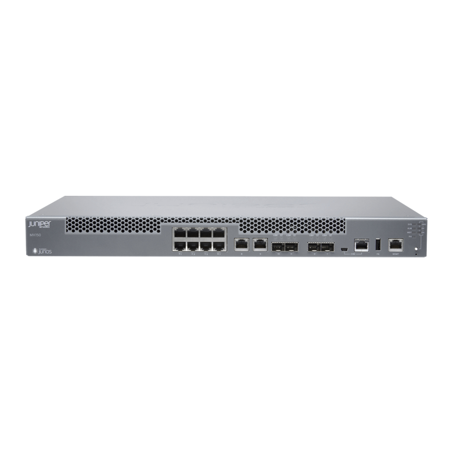
Port on page 91 Connecting an MX150 to a Network for Out-of-Band Management You can monitor and manage the MX150 by using a dedicated management channel. The MX150 has one management port, eight 1-Gigabit Ethernet RJ-45 ports, two 1-Gigabit Ethernet RJ-45 network or uplink ports, two 1-Gigabit Ethernet small form-factor pluggable (SFP) ports, and two 1/10-Gigabit Ethernet SFP+ ports. -
Page 106: Connecting An Mx150 To A Management Console
Connecting an MX150 to a Management Console on page 90 Connecting an MX150 to a Management Console MX150 has a console port with an RJ-45 connector. Use the console port to connect the device to a management console or to a console server. -
Page 107: Connecting An Mx150 To A Management Console Using Mini-Usb Type-B Console Port
If your laptop or PC does not have a DB-9 male connector pin or RJ-45 connector pin, you can connect your laptop or PC directly to an MX150 device by using a mini-USB cable that has a Standard-A USB connector on one end and a Mini-USB Type-B (5 pin) connector on the other end. - Page 108 1 mini-USB cable with Standard-A and Mini-USB Type- B (5-pin) connectors (not provided). To connect the MX150 to the console by using Mini-USB Type-B console port: Connect the Standard-A connector of the mini-USB cable to the host machine (PC or Laptop).
-
Page 109: Initially Configuring The Mx150
Initially Configuring the MX150 Configuring the MX150 on page 93 Configuring the MX150 You must perform the initial configuration of the MX150 through the console port using the command-line interface (CLI). Before you begin connecting and configuring an MX150, set the following parameter values on the console server or PC: Baud Rate—9600... - Page 110 To configure an IPV6 address, run the root@host# set interface fxp0 family inet6 address address v6_address NOTE: fxp0 is found on the front panel of the MX150 device. Configure the default gateway. [edit] root@host# set routing-options static route default next-hop address Enable the SSH service.
-
Page 111: Installing, Maintaining, And Replacing Components
PART 4 Installing, Maintaining, and Replacing Components Removing the MX150 on page 97 Replacing Transceivers on page 101 Maintaining and Replacing Fiber-Optic Cable on page 105 Contacting Customer Support and Returning the Chassis or Components on page 109 Copyright © 2017, Juniper Networks, Inc. - Page 112 MX150 3D Universal Edge Router Hardware Guide Copyright © 2017, Juniper Networks, Inc.
-
Page 113: Removing The Mx150
Removing an MX150 from a Rack or Cabinet on page 99 Powering Off an MX150 If you need to power off the MX150, follow the procedure in this topic. Before you power off the device: Ensure that you understand how to prevent electrostatic discharge damage. See “Prevention of Electrostatic Discharge Damage”... - Page 114 Attach the ESD grounding strap to your bare wrist and connect the strap to the ESD point on the chassis. Set the power switch to off ( ) position. Related Connecting AC Power to an MX150 on page 86 Documentation Copyright © 2017, Juniper Networks, Inc.
-
Page 115: Removing An Mx150 From A Rack Or Cabinet
Chapter 14: Removing the MX150 Removing an MX150 from a Rack or Cabinet If you need to relocate an installed MX150, use the procedure described in this topic. (The remainder of this topic uses rack to mean rack or cabinet.) - Page 116 MX150 3D Universal Edge Router Hardware Guide Copyright © 2017, Juniper Networks, Inc.
-
Page 117: Replacing Transceivers
(FRUs). You can remove and replace them without powering off the device or disrupting device functions. Before you begin removing a transceiver from the MX150, ensure that you have taken the necessary precautions for safe handling of lasers (see “Laser and LED Safety Guidelines... - Page 118 MX150 3D Universal Edge Router Hardware Guide CAUTION: Do not bend fiber-optic cables beyond their minimum bend radius. Bending the cables beyond their minimum bend radius can damage the cables and cause problems that are difficult to diagnose. Remove the cable connected to the transceiver (see “Disconnecting a Fiber-Optic...
-
Page 119: Installing A Transceiver In An Mx150
(FRUs). You can remove and replace them without powering off the device or disrupting device functions. Before you begin installing a transceiver in an MX150, ensure that you have taken the necessary precautions for safe handling of lasers (see “Laser and LED Safety Guidelines... -
Page 120: Figure 22: Installing A Transceiver In An Mx150
Figure 22: Installing a Transceiver in an MX150 Related Removing a Transceiver from an MX150 on page 101 Documentation Connecting a Fiber-Optic Cable to an MX150 on page 105 Copyright © 2017, Juniper Networks, Inc. -
Page 121: Maintaining And Replacing Fiber-Optic Cable
You can connect fiber-optic cables to the field-replaceable unit (FRU) optical transceivers installed in MX150 routers. Before you connect a fiber-optic cable to an optical transceiver installed in an MX150, ensure that you have taken the necessary precautions for safe handling of lasers (see “Laser and LED Safety Guidelines and Warnings for the MX150”... -
Page 122: Disconnecting A Fiber-Optic Cable From An Mx150
Disconnecting a Fiber-Optic Cable from an MX150 Before you disconnect a fiber-optic cable from an optical transceiver installed in an MX150, ensure that you have taken the necessary precautions for safe handling of lasers (see “Laser and LED Safety Guidelines and Warnings for the MX150” on page 137). -
Page 123: Maintaining Fiber-Optic Cables In An Mx150
Chapter 16: Maintaining and Replacing Fiber-Optic Cable To disconnect a fiber-optic cable from an optical transceiver installed in the MX150: (Recommended) Disable the port in which the transceiver is installed by including statement at the hierarchy level for the specific interface. - Page 124 Cletop-S Fiber Cleaner. Follow the directions in the cleaning kit you use. Related Disconnecting a Fiber-Optic Cable from an MX150 on page 106 Documentation Connecting a Fiber-Optic Cable to an MX150 on page 105 Copyright © 2017, Juniper Networks, Inc.
-
Page 125: Components
MX150 on page 113 Returning a MX150 Router or Component for Repair or Replacement If you need to return a MX150 router or component to Juniper Networks for repair or replacement, follow this procedure: Determine the serial number of the device or component. For instructions, see “Locating... -
Page 126: Locating The Serial Number On An Mx150
If you are returning a device to Juniper Networks for repair or replacement, you must locate the serial number of the device. You must provide the serial number to the Juniper Networks Technical Assistance Center (JTAC) when you contact them to obtain Return Materials Authorization (RMA). -
Page 127: Locating The Chassis Serial Number Id Label On An Mx150
Chapter 17: Contacting Customer Support and Returning the Chassis or Components Locating the Chassis Serial Number ID Label on an MX150 The serial number ID label is located on the back of the chassis on an MX150. See Figure 24 on page 111. -
Page 128: Packing Mx150 Components For Shipping
Close the top of the cardboard shipping box and seal it with packing tape. Write the RMA number on the exterior of the box to ensure proper tracking. Related Returning a MX150 Router or Component for Repair or Replacement on page 109 Documentation Copyright © 2017, Juniper Networks, Inc. -
Page 129: Contacting Customer Support To Obtain A Return Materials Authorization For An Mx150
Chapter 17: Contacting Customer Support and Returning the Chassis or Components Contacting Customer Support to Obtain a Return Materials Authorization for an MX150 If you are returning an MX150 router or component to Juniper Networks for repair or replacement, obtain a Return Materials Authorization (RMA) from the Juniper Networks Technical Assistance Center (JTAC). - Page 130 MX150 3D Universal Edge Router Hardware Guide Copyright © 2017, Juniper Networks, Inc.
-
Page 131: Troubleshooting
PART 5 Troubleshooting Alarm Messages on page 117 Copyright © 2017, Juniper Networks, Inc. - Page 132 MX150 3D Universal Edge Router Hardware Guide Copyright © 2017, Juniper Networks, Inc.
-
Page 133: Alarm Messages
Understanding Alarm Types and Severity Levels on MX150 on page 117 Understanding Alarm Types and Severity Levels on MX150 Alarms alert you to conditions that might prevent normal operation of the MX150. Table 29 on page 117 provides a list of alarm terms and definitions that might help you in monitoring the device. - Page 134 MX150 3D Universal Edge Router Hardware Guide Related MX150 Router Overview on page 3 Documentation Copyright © 2017, Juniper Networks, Inc.
-
Page 135: Safety And Compliance Information
Radiation and Laser Safety Guidelines and Warnings on page 137 Maintenance and Operational Safety Warnings on page 143 Electrical Safety Guidelines and Warnings on page 149 Agency Approvals and Compliance Statements on page 157 Copyright © 2017, Juniper Networks, Inc. - Page 136 MX150 3D Universal Edge Router Hardware Guide Copyright © 2017, Juniper Networks, Inc.
-
Page 137: General Safety Guidelines And Warnings
Operate the device only when it is properly grounded. Ensure that the separate protective earthing terminal provided on this device is permanently connected to earth. Replace fuses only with fuses of the same type and rating. Copyright © 2017, Juniper Networks, Inc. -
Page 138: Definitions Of Safety Warning Levels
MX150 3D Universal Edge Router Hardware Guide Do not open or remove chassis covers or sheet-metal parts unless instructions are provided in the hardware documentation for this device. Such an action could cause severe electrical shock. Do not push or force any objects through any opening in the chassis frame. Such an action could result in electrical shock or fire. - Page 139 Innan du utför arbete på någon utrustning måste du vara medveten om farorna med elkretsar och känna till vanligt förfarande för att förebygga skador. Related General Safety Guidelines and Warnings on page 121 Documentation Copyright © 2017, Juniper Networks, Inc.
-
Page 140: Qualified Personnel Warning
MX150 3D Universal Edge Router Hardware Guide Installation Instructions Warning on page 129 Maintenance and Operational Safety Guidelines and Warnings on page 143 Grounded Equipment Warning Laser and LED Safety Guidelines and Warnings Laser and LED Safety Guidelines and Warnings for the ACX5000 Router... -
Page 141: Warning Statement For Norway And Sweden
The equipment must be connected to an earthed mains socket-outlet. Advarsel Apparatet skal kobles til en jordet stikkontakt. Varning! Apparaten skall anslutas till jordat nätuttag. Related General Safety Guidelines and Warnings on page 121 Documentation Copyright © 2017, Juniper Networks, Inc. - Page 142 MX150 3D Universal Edge Router Hardware Guide Copyright © 2017, Juniper Networks, Inc.
-
Page 143: Fire Safety Requirements
In addition, you should establish procedures to protect your equipment in the event of a fire emergency. Juniper Networks products should be installed in an environment suitable for electronic equipment. We recommend that fire suppression equipment be available in the event of a fire in the vicinity of the equipment and that all local fire, safety, and electrical codes and ordinances be observed when you install and operate your equipment. - Page 144 To keep warranties effective, do not use a dry chemical fire extinguisher to control a fire at or near a Juniper Networks device. If a dry chemical fire extinguisher is used, the unit is no longer eligible for coverage under a service agreement.
-
Page 145: Installation Safety Guidelines And Warnings
CHAPTER 21 Installation Safety Guidelines and Warnings Installation Instructions Warning on page 129 Chassis Lifting Guidelines for MX150 on page 130 Restricted Access Warning on page 130 Ramp Warning on page 132 Rack-Mounting and Cabinet-Mounting Warnings on page 132 Installation Instructions Warning... -
Page 146: Chassis Lifting Guidelines For Mx150
Grounded Equipment Warning Chassis Lifting Guidelines for MX150 The weight of an MX150 is approximately 9.4 lb (4.3 kg). Observe the following guidelines for lifting and moving an MX150: Before installing the MX150, verify that the intended site meets the specified power, environmental, and clearance requirements. - Page 147 Related General Safety Guidelines and Warnings on page 121 Documentation General Electrical Safety Guidelines and Warnings on page 149 Installation Instructions Warning on page 129 Grounded Equipment Warning Copyright © 2017, Juniper Networks, Inc.
-
Page 148: Ramp Warning
MX150 3D Universal Edge Router Hardware Guide Ramp Warning WARNING: When installing the device, do not use a ramp inclined at more than 10 degrees. Waarschuwing Gebruik een oprijplaat niet onder een hoek van meer dan 10 graden. Varoitus Älä käytä sellaista kaltevaa pintaa, jonka kaltevuus ylittää 10 astetta. - Page 149 Les directives ci-dessous sont destinées à assurer la protection du personnel: Le rack sur lequel est monté le Juniper Networks switch doit être fixé à la structure du bâtiment. Si cette unité constitue la seule unité montée en casier, elle doit être placée dans le bas.
- Page 150 Le seguenti direttive vengono fornite per garantire la sicurezza personale: Il Juniper Networks switch deve essere installato in un telaio, il quale deve essere fissato alla struttura dell'edificio. Questa unità deve venire montata sul fondo del supporto, se si tratta dell'unica unità...
- Page 151 Para garantizar su seguridad, proceda según las siguientes instrucciones: El Juniper Networks switch debe instalarse en un bastidor fijado a la estructura del edificio. Colocar el equipo en la parte inferior del bastidor, cuando sea la única unidad en el mismo.
- Page 152 MX150 3D Universal Edge Router Hardware Guide Juniper Networks switch måste installeras i en ställning som är förankrad i byggnadens struktur. Om denna enhet är den enda enheten på ställningen skall den installeras längst ned på ställningen. Om denna enhet installeras på en delvis fylld ställning skall ställningen fyllas nedifrån och upp, med de tyngsta enheterna längst ned på...
-
Page 153: Radiation And Laser Safety Guidelines And Warnings
CHAPTER 22 Radiation and Laser Safety Guidelines and Warnings Laser and LED Safety Guidelines and Warnings for the MX150 on page 137 Radiation from Open Port Apertures Warning on page 141 Laser and LED Safety Guidelines and Warnings for the MX150... -
Page 154: Class 1M Laser Product Warning
MX150 3D Universal Edge Router Hardware Guide retina, so focusing the eye directly on a laser source—even a low-power laser—could permanently damage the eye. Class 1M Laser Product Warning WARNING: Class 1M laser product. Waarschuwing Laserproducten van Klasse 1M (IEC). -
Page 155: Class 1 Led Product Warning
Warnung Nicht direkt in den Strahl blicken und ihn nicht direkt mit optischen Geräten prüfen. Avvertenza Non fissare il raggio con gli occhi né usare strumenti ottici per osservarlo direttamente. Advarsel Stirr eller se ikke direkte p strlen med optiske instrumenter. Copyright © 2017, Juniper Networks, Inc. -
Page 156: Unterminated Fiber-Optic Cable Warning
MX150 3D Universal Edge Router Hardware Guide Aviso Não olhe fixamente para o raio, nem olhe para ele directamente com instrumentos ópticos. ¡Atención! No mirar fijamente el haz ni observarlo directamente con instrumentos ópticos. Varning! Rikta inte blicken in mot strålen och titta inte direkt på den genom optiska instrument. -
Page 157: Radiation From Open Port Apertures Warning
Varoitus Koska portin aukosta voi emittoitua näkymätöntä säteilyä, kun kuitukaapelia ei ole kytkettynä, vältä säteilylle altistumista äläkä katso avoimiin aukkoihin. Copyright © 2017, Juniper Networks, Inc. - Page 158 MX150 3D Universal Edge Router Hardware Guide Attention Des radiations invisibles à l'il nu pouvant traverser l'ouverture du port lorsqu'aucun câble en fibre optique n'y est connecté, il est recommandé de ne pas regarder fixement l'intérieur de ces ouvertures. Warnung Aus der Port-Öffnung können unsichtbare Strahlen emittieren, wenn kein Glasfaserkabel angeschlossen ist.
-
Page 159: Maintenance And Operational Safety Warnings
Attention Danger d'explosion si la pile n'est pas remplacée correctement. Ne la remplacer que par une pile de type semblable ou équivalent, recommandée par le fabricant. Jeter les piles usagées conformément aux instructions du fabricant. Copyright © 2017, Juniper Networks, Inc. -
Page 160: Jewelry Removal Warning
MX150 3D Universal Edge Router Hardware Guide Warnung Bei Einsetzen einer falschen Batterie besteht Explosionsgefahr. Ersetzen Sie die Batterie nur durch den gleichen oder vom Hersteller empfohlenen Batterietyp. Entsorgen Sie die benutzten Batterien nach den Anweisungen des Herstellers. Advarsel Det kan være fare for eksplosjon hvis batteriet skiftes på feil måte. -
Page 161: Lightning Activity Warning
Waarschuwing Tijdens onweer dat gepaard gaat met bliksem, dient u niet aan het systeem te werken of kabels aan te sluiten of te ontkoppelen. Varoitus Älä työskentele järjestelmän parissa äläkä yhdistä tai irrota kaapeleita ukkosilmalla. Copyright © 2017, Juniper Networks, Inc. -
Page 162: Operating Temperature Warning
6 in. (15.2 cm) of clearance around the ventilation openings. Waarschuwing Om te voorkomen dat welke switch van de Juniper Networks router dan ook oververhit raakt, dient u deze niet te bedienen op een plaats waar de maximale aanbevolen omgevingstemperatuur van 40°... -
Page 163: Product Disposal Warning
15,2 cm à volta das aberturas de ventilação. ¡Atención! Para impedir que un encaminador de la serie Juniper Networks switch se recaliente, no lo haga funcionar en un área en la que se supere la temperatura ambiente máxima recomendada de 40°... - Page 164 MX150 3D Universal Edge Router Hardware Guide Advarsel Endelig disponering av dette produktet må skje i henhold til nasjonale lover og forskrifter. Aviso A descartagem final deste produto deverá ser efectuada de acordo com os regulamentos e a legislação nacional.
-
Page 165: Electrical Safety Guidelines And Warnings
Install the device in compliance with the following local, national, and international electrical codes: United States—National Fire Protection Association (NFPA 70), United States National Electrical Code. Other countries—International Electromechanical Commission (IEC) 60364, Part 1 through Part 7. Copyright © 2017, Juniper Networks, Inc. -
Page 166: Action To Take After An Electrical Accident
MX150 3D Universal Edge Router Hardware Guide Evaluated to the TN power system. Canada—Canadian Electrical Code, Part 1, CSA C22.1. Locate the emergency power-off switch for the room in which you are working so that if an electrical accident occurs, you can quickly turn off the power. -
Page 167: Prevention Of Electrostatic Discharge Damage
151). If you are returning a component, place it in an antistatic bag before packing it. Figure 25: Placing a Component into an Antistatic Bag CAUTION ELECTROSTATIC SENSITIVE DEVICES DO NOT OPEN OR HANDLE EXCEPT AT A STATIC-FREE WORKSTATION Copyright © 2017, Juniper Networks, Inc. -
Page 168: Ac Power Electrical Safety Guidelines
MX150 3D Universal Edge Router Hardware Guide CAUTION: ANSI/TIA/EIA-568 cables such as Category 5e and Category 6 can get electrostatically charged. To dissipate this charge, always ground the cables to a suitable and safe earth ground before connecting them to the system. -
Page 169: Ac Power Disconnection Warning
Avvertenza Prima di lavorare su un telaio o intorno ad alimentatori, scollegare il cavo di alimentazione sulle unità CA. Advarsel Før det utføres arbeid på kabinettet eller det arbeides i nærheten av strømforsyningsenheter, skal strømledningen trekkes ut på vekselstrømsenheter. Copyright © 2017, Juniper Networks, Inc. -
Page 170: Tn Power Warning
MX150 3D Universal Edge Router Hardware Guide Aviso Antes de trabalhar num chassis, ou antes de trabalhar perto de unidades de fornecimento de energia, desligue o cabo de alimentação nas unidades de corrente alternada. ¡Atención! Antes de manipular el chasis de un equipo o trabajar cerca de una fuente de alimentación, desenchufar el cable de alimentación en los equipos... - Page 171 Chapter 24: Electrical Safety Guidelines and Warnings Grounded Equipment Warning Multiple Power Supplies Disconnection Warning Copyright © 2017, Juniper Networks, Inc.
- Page 172 MX150 3D Universal Edge Router Hardware Guide Copyright © 2017, Juniper Networks, Inc.
-
Page 173: Agency Approvals And Compliance Statements
CHAPTER 25 Agency Approvals and Compliance Statements Agency Approvals for MX150 on page 157 Compliance Statements for EMC Requirements for MX150 on page 158 Agency Approvals for MX150 The MX150 complies with the following standards: Safety CAN/CSA-C22.2 No. 60950-1 Information Technology Equipment... -
Page 174: Compliance Statements For Emc Requirements For Mx150
EN 61000-4-6 Low Frequency Common Immunity EN 61000-4-11 Voltage Dips and Sags Related Compliance Statements for EMC Requirements for MX150 on page 158 Documentation Compliance Statements for EMC Requirements for MX150 This topic describes the EMC requirements for the MX150 :... -
Page 175: European Community
Japan The preceding translates as follows: This is a Class A device. In a domestic environment this device might cause radio interference, in which case the user needs to take adequate measures. VCCI-A Copyright © 2017, Juniper Networks, Inc. -
Page 176: Korea
MX150 3D Universal Edge Router Hardware Guide Korea Korean Class A Warning The preceding translates as follows: This equipment is Industrial (Class A) electromagnetic wave suitability equipment and seller or user should take notice of it, and this equipment is to be used in the places except... -
Page 177: Nonregulatory Environmental Standards
Chapter 25: Agency Approvals and Compliance Statements Nonregulatory Environmental Standards NEBS compliance—These MX150 devices are Network Equipment Building System (NEBS) compliant. Those devices are designed to meet the following NEBS compliance standards: SR-3580 NEBS Criteria Levels (Level 4 Compliance) GR-1089-CORE: EMC and Electrical Safety for Network Telecommunications Equipment... - Page 178 MX150 3D Universal Edge Router Hardware Guide Copyright © 2017, Juniper Networks, Inc.
Need help?
Do you have a question about the MX150 and is the answer not in the manual?
Questions and answers