
Related Manuals for Juniper MX104


Summary of Contents for Juniper MX104
- Page 1 MX104 3D Universal Edge Router Hardware Guide Modified: 2017-08-07 Copyright © 2017, Juniper Networks, Inc.
- Page 2 END USER LICENSE AGREEMENT The Juniper Networks product that is the subject of this technical documentation consists of (or is intended for use with) Juniper Networks software. Use of such software is subject to the terms and conditions of the End User License Agreement (“EULA”) posted at http://www.juniper.net/support/eula/.
-
Page 3: Table Of Contents
System Overview ........... 3 MX104 3D Universal Edge Router Overview ....... 3 MX104 Chassis Overview . - Page 4 MX104 Routing Engine Buttons ........
- Page 5 Rack Requirements for MX104 Routers ........72...
- Page 6 MX104 Time of Day Port Specifications ....... . . 90...
- Page 7 Initially Configuring the MX104 Router ........129...
- Page 8 Installing an MX104 Transceiver ........167...
- Page 9 MX104 Chassis Serial Number Label ........206...
- Page 10 Agency Approvals for MX104 Routers ........253...
- Page 11 Figure 6: Alarm LEDs on the MX104 Router ....... 12...
- Page 12 Replacing Cooling System Component ......143 Figure 38: Removing the MX104 Air Filter ....... 144 Figure 39: Installing the Air Filter .
- Page 13 Figure 66: MX104 Fan Tray Serial Number Label ......207 Figure 67: MX104 MIC Serial Number Label ......207 Figure 68: MX104 Power Supply Serial Number Label .
- Page 14 MX104 3D Universal Edge Router Hardware Guide Copyright © 2017, Juniper Networks, Inc.
- Page 15 Table 11: MX104 Routing Engine Buttons ....... . . 23...
- Page 16 Table 47: MX104 MIC Interface Names ........
- Page 17 Unpacking the MX104 Router ........
- Page 18 MX104 3D Universal Edge Router Hardware Guide xviii Copyright © 2017, Juniper Networks, Inc.
-
Page 19: About The Documentation
® To obtain the most current version of all Juniper Networks technical documentation, see the product documentation page on the Juniper Networks website at http://www.juniper.net/techpubs/ If the information in the latest release notes differs from the information in the documentation, follow the product Release Notes. -
Page 20: Table 1: Notice Icons
MX104 3D Universal Edge Router Hardware Guide Table 1: Notice Icons Icon Meaning Description Informational note Indicates important features or instructions. Caution Indicates a situation that might result in loss of data or hardware damage. Warning Alerts you to the risk of personal injury or death. -
Page 21: Documentation Feedback
We encourage you to provide feedback, comments, and suggestions so that we can improve the documentation. You can provide feedback by using either of the following methods: Online feedback rating system—On any page of the Juniper Networks TechLibrary site , simply click the stars to rate the content, http://www.juniper.net/techpubs/index.html and use the pop-up form to provide us with information about your experience. -
Page 22: Requesting Technical Support
7 days a week, 365 days a year. Self-Help Online Tools and Resources For quick and easy problem resolution, Juniper Networks has designed an online self-service portal called the Customer Support Center (CSC) that provides you with the following features: Find CSC offerings: http://www.juniper.net/customers/support/... - Page 23 About the Documentation For international or direct-dial options in countries without toll-free numbers, see http://www.juniper.net/support/requesting-support.html Copyright © 2017, Juniper Networks, Inc. xxiii...
- Page 24 MX104 3D Universal Edge Router Hardware Guide xxiv Copyright © 2017, Juniper Networks, Inc.
-
Page 25: Overview
Chassis Components and Descriptions on page 9 Cooling System Components and Descriptions on page 19 Host Subsystem Components and Descriptions on page 21 Line Card Components and Descriptions on page 47 Power System Components and Descriptions on page 61 Copyright © 2017, Juniper Networks, Inc. - Page 26 MX104 3D Universal Edge Router Hardware Guide Copyright © 2017, Juniper Networks, Inc.
-
Page 27: System Overview
MX104 Component Redundancy on page 7 MX104 3D Universal Edge Router Overview The Juniper Networks MX104 3D Universal Edge Router is optimized for aggregating mobile, enterprise WAN, business, and residential access services. The MX104 router is designed for high-density access and pre-aggregation and is environmentally hardened to allow outside deployments in cabinets and remote terminals. -
Page 28: Mx104 Chassis Overview
MX104 Port and Interface Numbering on page 53 MX104 Chassis Overview on page 4 MX104 Chassis Overview The MX104 router contains a front panel with slots in which you can install field-replaceable units (FRUs). From the front of the chassis, you can see the following components (see... -
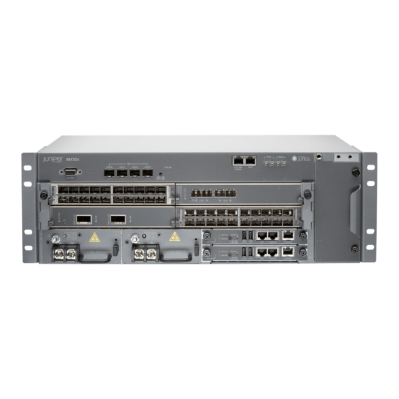
Page 29: Figure 3: Front View Of The Mx104 Router
Fan tray, which contains five fans and an air filter Four slots for installing MICs NOTE: For a detailed description of the MX104 port and interface numbering “MX104 Port and Interface Numbering” on page Two slots for installing either AC or DC power supplies, labeled... -
Page 30: Mx104 Hardware And Cli Terminology Mapping
MX104 3D Universal Edge Router Hardware Guide MX104 Hardware and CLI Terminology Mapping The MX104 router supports the components in Table 3 on page 6, listed in alphabetic order. Table 3: MX104 Routers Hardware Components and CLI Terminology Component Hardware Model Number CLI Name Description Chassis MX104 “MX104 3D Universal Edge Router... -
Page 31: Mx104 Component Redundancy
Chapter 1: System Overview MX104 Component Redundancy The MX104 chassis provides redundancy and resiliency. The hardware system is fully redundant, including power supplies, Routing Engines, and cooling system. A fully configured router is designed so that no single point of failure can cause the entire system to fail. - Page 32 MX104 3D Universal Edge Router Hardware Guide Copyright © 2017, Juniper Networks, Inc.
-
Page 33: Chassis Components And Descriptions
D-type connector. The external alarm contact has 15 pins that accept a single core wire from external alarm devices. A DE-15 alarm cable is required to connect the MX104 router to external alarm devices. Use the gauge wire appropriate for the external device that you are connecting. -
Page 34: Figure 4: Sample Output Alarm-Reporting Device
MX104 3D Universal Edge Router Hardware Guide Table 4: Alarm Relay Contact Functions Contact Name Contact Name Function Contact 1 Normally Open [NO] Current is not flowing through Contact 1 and Contact 2 [REF] when operating normally. When the current flows, the closed alarm is generated. -
Page 35: Mx104 Leds Overview
Chapter 2: Chassis Components and Descriptions Figure 5: Sample Input Alarm-Reporting Device Related MX104 3D Universal Edge Router Overview on page 3 Documentation MX104 Chassis Overview on page 4 MX104 Alarm Contact Port Specifications on page 87 MX104 LEDs Overview... -
Page 36: System Led On The Front Panel
MX104 3D Universal Edge Router Hardware Guide Figure 6: Alarm LEDs on the MX104 Router Table 5 on page 12 describes the alarm LED in more detail. Table 5: Alarm LEDs on the Front Panel Shape Color State LED Control Name... -
Page 37: Mic Leds
Three LEDs indicate the status of the Routing Engine. For more information, see “MX104 Routing Engine LEDs” on page Related Troubleshooting Resources for MX104 Routers on page 197 Documentation MX104 Chassis Overview on page 4 MX104 LEDs Overview Alarm LEDs on the Front Panel on page 13... -
Page 38: System Led On The Front Panel
MX104 3D Universal Edge Router Hardware Guide Figure 7: Alarm LEDs on the MX104 Router Table 5 on page 12 describes the alarm LED in more detail. Table 7: Alarm LEDs on the Front Panel Shape Color State LED Control Name... -
Page 39: Mic Leds
Three LEDs indicate the status of the Routing Engine. For more information, see “MX104 Routing Engine LEDs” on page Related Troubleshooting Resources for MX104 Routers on page 197 Documentation MX104 Chassis Overview on page 4 MX104 LEDs Overview Alarm LEDs on the Front Panel on page 15... -
Page 40: System Led On The Front Panel
MX104 3D Universal Edge Router Hardware Guide Figure 8: Alarm LEDs on the MX104 Router Table 5 on page 12 describes the alarm LED in more detail. Table 9: Alarm LEDs on the Front Panel Shape Color State LED Control Name... -
Page 41: Mic Leds
Three LEDs indicate the status of the Routing Engine. For more information, see “MX104 Routing Engine LEDs” on page Related Troubleshooting Resources for MX104 Routers on page 197 Documentation MX104 Chassis Overview on page 4 MX104 Clocking and Timing Ports Overview... - Page 42 MX104 3D Universal Edge Router Hardware Guide Related Connecting the MX104 Router to External Clocking and Timing Devices on page 123 Documentation MX104 BITS Port Specifications on page 89 MX104 1-PPS and 10-MHz GPS Port Specifications on page 90 MX104 Time of Day Port Specifications on page 90...
-
Page 43: Cooling System Components And Descriptions
Cooling System Components and Descriptions MX104 Cooling System and Airflow Overview on page 19 MX104 Cooling System and Airflow Overview The cooling system in an MX104 router consists of the following components (see Figure 9 on page 19): Fan tray... -
Page 44: Figure 10: Cooling System And Airflow In An Mx104 Router
Routing Engine shuts down the system by disabling output power from each power supply. Related Preparing the Site for the MX104 Router Overview on page 71 Documentation Maintaining the MX104 Air Filter on page 190... -
Page 45: Host Subsystem Components And Descriptions
If the master Routing Engine fails or is removed and the backup is configured appropriately, the backup takes over as the master. The backup Routing Engine is hot-insertable and hot-removable. The MX104 router supports the Routing Engine with model number RE-MX104. Figure 11: MX104 Routing Engine MX104 Routing Engine Components on page 22 MX104 Routing Engine Buttons on page 22 Copyright ©... -
Page 46: Mx104 Routing Engine Components
MX104 3D Universal Edge Router Hardware Guide MX104 Routing Engine LEDs on page 23 MX104 Boot Sequence on page 24 MX104 Routing Engine Components Five ports, located on the right side of the Routing Engine, connect the Routing Engine to one or more external devices on which system administrators can issue Junos OS command-line interface (CLI) commands to manage the router. -
Page 47: Mx104 Routing Engine Leds
Chapter 4: Host Subsystem Components and Descriptions Table 11: MX104 Routing Engine Buttons Label Action Description Indicator Press for 2 Routing Engine transitions online Green LED is on steadily. ONLINE ONLINE seconds. when pressed. OFFLINE Press for 4 Routing Engine transitions offline All LEDs are off. -
Page 48: Mx104 Boot Sequence
The port is not receiving data. MX104 Boot Sequence The MX104 router ships with Junos OS preinstalled and ready to be configured when the router is powered on. One eight-GB internal NAND Flash memory ( ) acts as the hard drive. -
Page 49: Mx104 Routing Engine Components
Chapter 4: Host Subsystem Components and Descriptions Figure 12: MX104 Routing Engine MX104 Routing Engine Components on page 25 MX104 Routing Engine Buttons on page 26 MX104 Routing Engine LEDs on page 26 MX104 Boot Sequence on page 27 MX104 Routing Engine Components... -
Page 50: Mx104 Routing Engine Buttons
MX104 3D Universal Edge Router Hardware Guide MX104 Routing Engine Buttons Each Routing Engine has two push-button controls. The buttons, labeled ONLINE OFFLINE , are located directly on the faceplate of the Routing Engine. Table 11 on page 23 RESET describes the functions of the buttons. -
Page 51: Mx104 Boot Sequence
The port is not receiving data. MX104 Boot Sequence The MX104 router ships with Junos OS preinstalled and ready to be configured when the router is powered on. One eight-GB internal NAND Flash memory ( ) acts as the hard drive. -
Page 52: Mx104 Routing Engine Components
MX104 3D Universal Edge Router Hardware Guide Figure 13: MX104 Routing Engine MX104 Routing Engine Components on page 28 MX104 Routing Engine Buttons on page 29 MX104 Routing Engine LEDs on page 29 MX104 Boot Sequence on page 30 MX104 Routing Engine Components... -
Page 53: Mx104 Routing Engine Buttons
Each Routing Engine has two push-button controls. The buttons, labeled ONLINE OFFLINE , are located directly on the faceplate of the Routing Engine. Table 11 on page 23 RESET describes the functions of the buttons. Table 17: MX104 Routing Engine Buttons Label Action Description Indicator ONLINE... -
Page 54: Mx104 Boot Sequence
The port is not receiving data. MX104 Boot Sequence The MX104 router ships with Junos OS preinstalled and ready to be configured when the router is powered on. One eight-GB internal NAND Flash memory ( ) acts as the hard drive. -
Page 55: Table 20: Routing Engine Specifications
4 GB 10.4 Ethernet CompactFlash card RE-S-MX104 1.8-GHz 4 GB Gigabit – 8 GB NAND 13.2 Ethernet Flash RE-B-1800x1-4G 1.73-GHz 4 GB Gigabit 64 GB SSD 4 GB 12.1R2, 11.4R4, and Ethernet CompactFlash 12.2R1 card Copyright © 2017, Juniper Networks, Inc. -
Page 56: Table 21: End-Of-Life Routing Engine Specifications
MX104 3D Universal Edge Router Hardware Guide Table 20: Routing Engine Specifications (continued) Routing Connection First Junos OS Engine Processor Memory to PFEs Disk Media Support RE-MX2000-1800x4 1800-GHz 16 GB Gigabit 32 GB SSD 4 GB Fixed 12.3R2 Ethernet Internal... -
Page 57: Supported Routing Engines By Router
Routing Engine in the specified router, the management Ethernet interface, and the internal Ethernet interfaces for each Routing Engine. M7i Routing Engines on page 34 M10i Routing Engines on page 34 M40e Routing Engines on page 35 Copyright © 2017, Juniper Networks, Inc. -
Page 58: M7I Routing Engines
MX104 3D Universal Edge Router Hardware Guide M120 Routing Engines on page 35 M320 Routing Engines on page 36 MX5, MX10, MX40, and MX80 Routing Engine on page 36 MX104 Routing Engines on page 37 MX240 Routing Engines on page 37... -
Page 59: M40E Routing Engines
Supported Management Name in CLI 32-bit Junos OS 64-bit Junos Ethernet Internal Ethernet Model Number Output Release OS Release Interface Interface RE-A-1000-2048 8.0R2 – fxp0 fxp1 RE-A-1000 fxp2 RE-A-2000-4096 8.0R2 – fxp0 RE-A-2000 bcm0 Copyright © 2017, Juniper Networks, Inc. -
Page 60: M320 Routing Engines
MX104 3D Universal Edge Router Hardware Guide Table 25: M120 Routing Engines (continued) First First Supported Supported Management Name in CLI 32-bit Junos OS 64-bit Junos Ethernet Internal Ethernet Model Number Output Release OS Release Interface Interface RE-A-1800X2-8G 11.4R5 10.4... -
Page 61: Mx104 Routing Engines
NOTE: em1 is used to communicate with the MS-MIC when it is inserted. MX104 Routing Engines Table 28 on page 37 lists the Routing Engines supported by MX104 routers. Table 28: MX104 Routing Engines First Supported First Supported Management Model... -
Page 62: Mx480 Routing Engines
MX104 3D Universal Edge Router Hardware Guide Table 29: MX240 Supported Routing Engines (continued) First First Supported Supported Management Internal Name in CLI 32-bit Junos OS 64-bit Junos Ethernet Ethernet Model Number Output Release OS Release Interface Interface RE-S-1800X4-8G 11.4R5 10.4... -
Page 63: Mx960 Routing Engines
RE-S-1800x2 11.4R5 10.4 fxp0 TSB16556 details: 12.1R3 RE-S-1800X4-8G 11.4R5 10.4 fxp0 RE-S-1800x4 12.1R3 RE-S-1800X4-16G 11.4R5 10.4 fxp0 RE-S-1800x4 12.1R3 RE-S-1800X4-32G-S 12.3R4 12.3R4 fxp0 RE-S-1800x4 13.2R1 13.2R1 RE-S-X6-64G RE-S-2X00x6 – 15.1F4 fxp0 ixlv0, igb0 16.1R1 Copyright © 2017, Juniper Networks, Inc. -
Page 64: Mx2008 Routing Engines
MX104 3D Universal Edge Router Hardware Guide MX2008 Routing Engines Table 32 on page 40 lists the Routing Engines supported by MX2008 routers. Table 32: MX2008 Supported Routing Engines Management Internal Name in CLI First Supported 64-bit Junos Ethernet Ethernet... -
Page 65: Ptx3000 Routing Engines
Name in CLI First Supported Junos OS Ethernet Internal Ethernet Model Number Output Release Interface Interface RE-DUO-C2600-16G 12.1X48 ixgbe0 RE-DUO-2600 12.3 ixgbe1 13.2 NOTE: The PTX5000 does not support Junos OS Releases 12.1, 12.2, or 13.1. Copyright © 2017, Juniper Networks, Inc. -
Page 66: T320 Routing Engines
MX104 3D Universal Edge Router Hardware Guide Table 36: PTX5000 Routing Engines (continued) Management Name in CLI First Supported Junos OS Ethernet Internal Ethernet Model Number Output Release Interface Interface RE-PTX-X8-64G RE-PTX-2X00x8 15.1F4 ixlv0 16.1R1 ixlv1 T320 Routing Engines Table 37 on page 42 lists the Routing Engines supported by the T320 router. -
Page 67: T1600 Routing Engines
Model Number Output Junos OS Release Release Interface Interface RE-600-2048 (EOL RE-3.0 – fxp0 fxp1 TSB14373 details: RE-3.0 fxp2 (RE-600) RE-1600-2048 (EOL RE-4.0 – fxp0 fxp1 details: TSB14374 (RE-1600) fxp2 RE-A-2000-4096 RE-A-2000 – fxp0 bcm0 Copyright © 2017, Juniper Networks, Inc. -
Page 68: T4000 Routing Engines
MX104 3D Universal Edge Router Hardware Guide Table 39: T1600 Routing Engines (continued) First Supported Management Internal Name in CLI First Supported 32-bit 64-bit Junos OS Ethernet Ethernet Model Number Output Junos OS Release Release Interface Interface RE-DUO-C1800-8G RE-TXP-LCC 32-bit Junos OS on a T1600... -
Page 69: Tx Matrix Plus Routing Engines
Table 43: Routing Engines on TX Matrix Plus with 3D SIBs First Supported First Supported Management Internal Name in CLI 32-bit Junos OS 64-bit Junos OS Ethernet Ethernet Model Number Output Release Release Interface Interface RE-DUO-C2600-16G 64-bit Junos OS: 11.4 ixgbe0 RE-TXP-SFC RE-DUO-2600 ixgbe1 Copyright © 2017, Juniper Networks, Inc. - Page 70 MX104 3D Universal Edge Router Hardware Guide Related Routing Engine Specifications on page 30 Documentation Understanding Internal Ethernet Interfaces Understanding Management Ethernet Interfaces Copyright © 2017, Juniper Networks, Inc.
-
Page 71: Chapter 5 Line Card Components And Descriptions
MIC LEDs on page 49 Front-Pluggable MICs Modular Interface Cards (MICs) install into four slots in the front of the MX104 router and provide the physical connections to various network media types. MICs are hot-removable and hot-insertable. The slots are labeled , and . - Page 72 MX104 3D Universal Edge Router Hardware Guide The built-in 10-Gigabit Ethernet MIC has the following components: Hardware features: Four 10-Gigabit Ethernet ports labeled 2/0/0 through 2/0/3 , left to right High-performance throughput on each port at speeds up to 10 Gbps Line-rate on all four 10-Gigabit Ethernet ports LAN-PHY mode at 10.3125 Gbps...
-
Page 73: Mic Leds
MX104 Port and Interface Numbering on page 53 Documentation Replacing an MX104 MIC on page 161 Maintaining the MX104 MICs and Network Ports on page 192 MICs Supported by MX Series Routers The following tables list the first supported Junos OS release for the MX Series. - Page 74 MX104 3D Universal Edge Router Hardware Guide Table 45: MICs Supported by MX240, MX480, MX960, MX2008, MX2010, and MX2020 Routers (continued) MX240, MX480, MX960 MX2008 MX2010 MX2020 MIC Name MIC Model Number Ports Routers Routers Routers Routers DS3/E3 MIC MIC-3D-8DS3-E3, 11.4...
-
Page 75: Line Card Components And Descriptions
C o n t i n u i t y 16.1R1 16.1R1 later later Tri-Rate Tri-Rate MIC MIC-3D-40GE-TX 10.2 15.1F7 12.3 12.3 Services Multiservices MIC MS-MIC-16G 13.2 15.1F7 13.2 13.2 SONET/SDH SONET/SDH OC192/STM64 MIC MIC-3D-1OC192-XFP 12.2 15.1F7 12.3 12.3 with XFP Copyright © 2017, Juniper Networks, Inc. -
Page 76: Table 46: Mics Supported By Mx5, Mx10, Mx40, Mx80, And Mx104 Routers
MX104 3D Universal Edge Router Hardware Guide Table 46: MICs Supported by MX5, MX10, MX40, MX80, and MX104 Routers MIC Name MIC Model Number P o r t s MX10 MX40 MX80 M X 1 0 4 ATM MIC with SFP MIC-3D-8OC3-2OC12-ATM 12.1... -
Page 77: Mx104 Port And Interface Numbering
Identifying Interface Numbers on the Hardware on page 53 Identifying Interface Numbers in the CLI on page 55 Identifying Interface Numbers on the Hardware Each MX104 router has three built-in MPCs, which are represented in the CLI as FPC 0 through FPC 2 . -
Page 78: Figure 14: Mx104 Interface Port Mapping Example
MX104 3D Universal Edge Router Hardware Guide MPC 0 and MPC 1 have two slots each that accept MICs. The MICs are represented as in the CLI and are logically divided into PICs depending on their type. A MIC 0... -
Page 79: Identifying Interface Numbers In The Cli
Ethernet interface For a complete list of media types, see Interface Naming Overview. fpc—Slot in which the MPC is installed. On the MX104 router, the three MPCs are built into the chassis and are represented in the CLI as... - Page 80 MX104 3D Universal Edge Router Hardware Guide Midplane REV 28 750-044219 CAAX5767 MX104 PEM 0 REV 03 740-045932 1H073050110 DC Power Entry Module PEM 1 REV 03 740-045932 1H073050017 DC Power Entry Module Routing Engine 0 REV 03 750-053342 CABP2893...
- Page 81 10.1.8.11/24 multiservice ge-1/1/9 ge-1/1/9.0 inet 10.1.9.11/24 multiservice show interfaces terse command displays the four SONET/SDH interfaces for the MIC installed in MIC slot through coc3-0/2/0 co3-2/0/3 user@host> show interfaces terse Copyright © 2017, Juniper Networks, Inc.
-
Page 82: Mx104 Modular Interface Card (Mic) Overview
MIC LEDs on page 60 Front-Pluggable MICs Modular Interface Cards (MICs) install into four slots in the front of the MX104 router and provide the physical connections to various network media types. MICs are hot-removable and hot-insertable. The slots are labeled , and . - Page 83 Fiber-optic 10-gigabit small form-factor pluggable (SFP+) transceivers: Connector: Duplex LC/PC (Rx and Tx) 10GBASE-SR (model numbers EX-SFP-10GE-SR, EX-SFP-10GE-USR, and SFPP-10GE-SR) 10GBASE-LR (model numbers EX-SFP-10GE-LR and SFPP-10GE-LR) 10GBASE-LRM (model number SFPP-10GE-LRM) Optical interface specifications—see 10-Gigabit Ethernet 10GBASE Optical Interface Specifications. Copyright © 2017, Juniper Networks, Inc.
-
Page 84: Mic Leds
Yellow Link is online. – No link. Related MX104 Port and Interface Numbering on page 53 Documentation Replacing an MX104 MIC on page 161 Maintaining the MX104 MICs and Network Ports on page 192 Copyright © 2017, Juniper Networks, Inc. -
Page 85: Power System Components And Descriptions
MX104 Power Overview on page 61 MX104 Power Overview on page 63 MX104 Power Overview The MX104 router uses either AC or DC power supplies (see Figure 15 on page 62 Figure 16 on page 62). The power supplies are located in the front of the chassis and offer 1+1 redundancy. -
Page 86: Dc Power Supplies
MX104 3D Universal Edge Router Hardware Guide Each inlet requires a dedicated AC power feed and a dedicated customer site circuit breaker. We recommend that you use a dedicated customer site circuit breaker rated for 10 A (100 VAC), or as required by local code. -
Page 87: Mx104 Power Overview
Related Connecting AC Power Cords to the MX104 Router on page 115 Documentation Connecting DC Power Cables to the MX104 Router on page 117 MX104 AC Power Specifications on page 95... -
Page 88: Ac Power Supplies
MX104 3D Universal Edge Router Hardware Guide Redundant power supplies are hot-removable and hot-insertable. When you remove a power supply from a router that uses only one power supply, the router might shut down depending on your configuration. AC Power Supplies on page 64... -
Page 89: Power Supply Leds
Related Connecting AC Power Cords to the MX104 Router on page 115 Documentation Connecting DC Power Cables to the MX104 Router on page 117 MX104 AC Power Specifications on page 95 MX104 DC Power Specifications on page 99 Copyright ©... - Page 90 MX104 3D Universal Edge Router Hardware Guide Copyright © 2017, Juniper Networks, Inc.
-
Page 91: Site Planning, Preparation, And Specifications
Preparation Overview on page 69 Transceiver and Cable Specifications on page 79 Port Cable and Pinout Specifications on page 83 Power Specifications on page 93 AC Power Specifications on page 95 DC Power Specifications on page 99 Copyright © 2017, Juniper Networks, Inc. - Page 92 MX104 3D Universal Edge Router Hardware Guide Copyright © 2017, Juniper Networks, Inc.
-
Page 93: Preparation Overview
Routers on page 75 MX104 Router Grounding Specifications on page 76 MX104 Router Physical Specifications The MX104 router is a rigid sheet-metal structure that houses the hardware components. Table 51 on page 69 summarizes the physical specifications of the MX104 router and its components. -
Page 94: Mx104 Router Environmental Specifications
MX104 3D Universal Edge Router Hardware Guide Related MX104 Router Environmental Specifications on page 70 Documentation MX104 Router Environmental Specifications The router must be installed in a rack or cabinet housed in a dry, clean, well-ventilated, and temperature-controlled environment. Ensure that these environmental guidelines are followed: The site must be as dust-free as possible, because dust can clog air intake vents and filters, reducing the efficiency of the router cooling system. -
Page 95: Preparing The Site For The Mx104 Router Overview
General Electrical Safety Guidelines and Electrical Codes for Juniper Networks Devices on page 245 MX104 AC Power Electrical Safety Guidelines and Warnings on page 246 MX104 DC Power Electrical Safety Guidelines on page 247 Verify that your rack or cabinet meets the minimum requirements for the installation of the router. -
Page 96: Rack Requirements For Mx104 Routers
“Maintaining Cables That Connect to MX104 Network Ports” on page 191. Related Installing and Connecting an MX104 Router Overview on page 109 Documentation Rack Requirements for MX104 Routers You can mount the router on two-post racks or four-post racks. Rack requirements consist of:... -
Page 97: Cabinet Requirements For Mx104 Routers
Related Cabinet Requirements for MX104 Routers on page 73 Documentation Installing and Connecting an MX104 Router Overview on page 109 Cabinet Requirements for MX104 Routers You can mount the router in a cabinet that contains a 19-in. (48.3 cm) rack. -
Page 98: Table 54: Cabinet Requirements And Specifications For The Mx104 Router
A cabinet larger than the minimum required provides better airflow and reduces the chance of overheating. Related Preparing the Site for the MX104 Router Overview on page 71 Documentation Rack Requirements for MX104 Routers on page 72 Clearance Requirements for Airflow and Hardware Maintenance on MX104 Routers... -
Page 99: Clearance Requirements For Airflow And Hardware Maintenance On Mx104
30 in. (72.6 cm) in front of the rack and 24 in. (61.0 cm) behind the router. Figure 19: MX104 Chassis Dimensions and Clearance Requirements Related Preparing the Site for the MX104 Router Overview on page 71 Documentation Rack Requirements for MX104 Routers on page 72... -
Page 100: Routers
The grounding points fit SAE 10-32 screws (American). The grounding points are spaced at 0.625-in. (15.86-mm) centers. Figure 20: Grounding Points on the MX104 Routers NOTE: All bare grounding connection points to the router must be cleaned and coated with an antioxidant solution before grounding the router. -
Page 101: Grounding Cable Lug Specifications
The grounding cable lug, screws, and washers are supplied with the router. See Figure 21 on page 77 for AC systems and Figure 22 on page 78 for 24 VDC systems. Figure 21: Grounding Cable Lug for MX104 AC Systems Copyright © 2017, Juniper Networks, Inc. -
Page 102: Grounding Cable Specifications
C wire, or as required by the local code. See Figure 22 on page 78 Related Connecting the MX104 Router to Earth Ground on page 113 Documentation Preventing Electrostatic Discharge Damage to an MX104 Router on page 220 Copyright © 2017, Juniper Networks, Inc. -
Page 103: Transceiver And Cable Specifications
You can use the Hardware Compatibility Tool to find information about the pluggable transceivers supported on your Juniper Networks device. To calculate the power budget and power margin, perform the following tasks: Calculating Power Budget for Fiber-Optic Cable on page 79... -
Page 104: Calculating Power Margin For Fiber-Optic Cable
MX104 3D Universal Edge Router Hardware Guide Calculating Power Margin for Fiber-Optic Cable After calculating a link's power budget, you can calculate the power margin (P ), which represents the amount of power available after subtracting attenuation or link loss (LL) from the power budget (P ). -
Page 105: Understanding Fiber-Optic Cable Signal Loss, Attenuation, And Dispersion
Compared with multimode fiber, single-mode fiber has higher bandwidth and can carry signals for longer distances. Exceeding the maximum transmission distances can result in significant signal loss, which causes unreliable transmission. Copyright © 2017, Juniper Networks, Inc. -
Page 106: Attenuation And Dispersion In Fiber-Optic Cable
The optical power budget must allow for the sum of component attenuation, power penalties (including those from dispersion), and a safety margin for unexpected losses. Related Determining Transceiver Support and Specifications for Juniper Networks Devices Documentation Copyright © 2017, Juniper Networks, Inc. -
Page 107: Port Cable And Pinout Specifications
MX104 Clocking and Timing Ports Overview on page 83 MX104 Routing Engine Ethernet Port Specifications on page 84 MX104 Routing Engine Auxiliary and Console Ports Specifications on page 85 MX104 Routing Engine USB Port Specifications on page 86 MX104 Alarm Contact Port Specifications on page 87... -
Page 108: Mx104 Routing Engine Ethernet Port Specifications
MX104 3D Universal Edge Router Hardware Guide Timing output when configured as BC Related Connecting the MX104 Router to External Clocking and Timing Devices on page 123 Documentation MX104 BITS Port Specifications on page 89 MX104 1-PPS and 10-MHz GPS Port Specifications on page 90... -
Page 109: Mx104 Routing Engine Auxiliary And Console Ports Specifications
Cable Specifications on page 85 Pinouts on page 85 Cable Specifications Table 58 on page 85 lists the specifications for the cables that connect to console port. Table 58: MX104 Routing Engine Console Port Cable Specifications Specification Value Cable specification RS-232 (EIA-232) serial cable Cable/wire supplied One 6-ft (1.83-m) length with RJ-45/DB-9... -
Page 110: Mx104 Routing Engine Usb Port Specifications
Documentation Maintaining the MX104 Routing Engines on page 192 MX104 Routing Engine USB Port Specifications The following Juniper Networks USB Flash drives have been tested and are officially supported for the USB port on all MX Series routers: RE-USB-1G-S RE-USB-2G-S... -
Page 111: Mx104 Alarm Contact Port Specifications
Chapter 9: Port Cable and Pinout Specifications Related MX104 Routing Engine Overview on page 21 Documentation Initially Configuring the MX104 Router on page 129 MX104 Alarm Contact Port Specifications Cable Specifications Table 60 on page 87 lists the specifications for the cables that connect to the ALARM port. - Page 112 MX104 3D Universal Edge Router Overview on page 3 Documentation MX104 Chassis Overview on page 4 MX104 LEDs Overview on page 11 MX104 Alarm Contact Port Overview on page 9 Connecting the MX104 Router to an External Alarm-Reporting Device on page 124 Copyright © 2017, Juniper Networks, Inc.
-
Page 113: Mx104 Bits Port Specifications
RJ-45 connector (see Figure 23 on page 89). You must ensure that the cable pinouts match the pinouts described in Table 63 on page Figure 23: RJ-48 Connector for MX104 BITS Ports Table 62: MX104 BITS Port Cable Specifications Specification Value Cable... -
Page 114: Mx104 1-Pps And 10-Mhz Gps Port Specifications
– Reserved – Related Connecting the MX104 Router to External Clocking and Timing Devices on page 123 Documentation MX104 1-PPS and 10-MHz GPS Port Specifications The router contains four ports that support 1-pulse-per-second (PPS) and 10-MHz GPS signals. These signals are internally isolated and have surge protection. -
Page 115: Port Pinouts
Reserved – Reserved – Related MX104 3D Universal Edge Router Overview on page 3 Documentation MX104 Chassis Overview on page 4 MX104 LEDs Overview on page 11 MX104 Clocking and Timing Ports Overview on page 17 Copyright © 2017, Juniper Networks, Inc. - Page 116 MX104 3D Universal Edge Router Hardware Guide Copyright © 2017, Juniper Networks, Inc.
-
Page 117: Power Specifications
Power Specifications MX104 Power Consumption on page 93 MX104 Power Consumption The MX104 router supports installation of up to two AC or DC power supplies in slots labeled on the front of the router. Table 67 on page 93 lists the power consumed by the MX104 router. - Page 118 MX104 3D Universal Edge Router Hardware Guide Copyright © 2017, Juniper Networks, Inc.
-
Page 119: Ac Power Specifications
Related Connecting AC Power Cords to the MX104 Router on page 115 Documentation Replacing an MX104 AC Power Supply on page 170 Copyright © 2017, Juniper Networks, Inc. -
Page 120: Mx104 Ac Power Cord Specifications
MX104 3D Universal Edge Router Hardware Guide MX104 AC Power Electrical Safety Guidelines and Warnings on page 246 MX104 AC Power Cord Specifications on page 96 MX104 AC Power Cord Specifications Each AC power supply has a single AC appliance inlet that requires a dedicated AC power feed. - Page 121 Use power cords rated up to 149° F (65° C) for ambient temperatures up to 140° F (60° C). Related Connecting AC Power Cords to the MX104 Router on page 115 Documentation Replacing an MX104 AC Power Supply on page 170...
- Page 122 MX104 3D Universal Edge Router Hardware Guide Copyright © 2017, Juniper Networks, Inc.
-
Page 123: Dc Power Specifications
MX104 DC Power Specifications on page 99 MX104 DC Power Cable and Lug Specifications on page 100 MX104 DC Power Specifications The MX104 power supply contains DC power terminals to connect power to the router and supports the specifications shown in Table 70 on page... -
Page 124: Mx104 Dc Power Cable And Lug Specifications
MX104 3D Universal Edge Router Hardware Guide DC Power Electrical Safety Warnings for Juniper Networks Devices on page 248 MX104 DC Power Cable and Lug Specifications on page 100 MX104 DC Power Cable and Lug Specifications DC Power Cable Lug Specifications on page 100... -
Page 125: Dc Power Specifications
Chapter 12: DC Power Specifications DC Power Electrical Safety Warnings for Juniper Networks Devices on page 248 MX104 DC Power Specifications on page 99 Copyright © 2017, Juniper Networks, Inc. - Page 126 MX104 3D Universal Edge Router Hardware Guide Copyright © 2017, Juniper Networks, Inc.
-
Page 127: Initial Installation And Configuration
Installing the MX104 Router on page 109 Connecting the MX104 Router to Power on page 113 Connecting the MX104 Router to the Network on page 121 Initially Configuring the MX104 Router on page 129 Copyright © 2017, Juniper Networks, Inc. - Page 128 MX104 3D Universal Edge Router Hardware Guide Copyright © 2017, Juniper Networks, Inc.
-
Page 129: Unpacking The Mx104 Router
Unpacking an MX104 Router on page 105 Parts Inventory (Packing List) for an MX104 Router on page 106 Unpacking an MX104 Router The MX104 routers are shipped in a cardboard carton, secured with foam packing material. The carton also contains an accessory box. CAUTION: MX104 routers are maximally protected inside the shipping carton. -
Page 130: Parts Inventory (Packing List) For An Mx104 Router
Preparing the Site for the MX104 Router Overview on page 71 Parts Inventory (Packing List) for an MX104 Router The MX104 routers are shipped in a cardboard carton, secured with foam packing material. The carton also contains an accessory box. -
Page 131: Table 72: Accessory Box Parts List For An Mx104 Router
Chapter 13: Unpacking the MX104 Router Table 71: Parts List for a Fully Configured MX104 Router (continued) Component Quantity Air filter Quick start installation instructions Blank panels for slots without components installed One blank panel for each slot not occupied by a component... - Page 132 Related MX104 3D Universal Edge Router Overview on page 3 Documentation Unpacking an MX104 Router on page 105 Copyright © 2017, Juniper Networks, Inc.
-
Page 133: Installing The Mx104 Router
Connect the router to external devices. See: Connecting the MX104 Router to Management Devices on page 121 Connecting the MX104 Router to External Clocking and Timing Devices on page 123 Connecting the MX104 Router to an External Alarm-Reporting Device on page 124 Connect power to the router: AC-powered models—See... -
Page 134: Installing The Mx104 Router In The Rack
MX104 3D Universal Edge Router Hardware Guide DC-powered models—See “Connecting DC Power Cables to the MX104 Router” on page 117. Perform initial configuration of the router by following instructions in “Initially Configuring the MX104 Router” on page 129. Related MX104 3D Universal Edge Router Overview on page 3... -
Page 135: Figure 25: Install The Front-Mounted Router In The Rack
3— Mounting screws 2—MX104 router Related Preparing the Site for the MX104 Router Overview on page 71 Documentation Installing and Connecting an MX104 Router Overview on page 109 Connecting the MX104 Router to Earth Ground on page 113 Copyright © 2017, Juniper Networks, Inc. - Page 136 MX104 3D Universal Edge Router Hardware Guide Copyright © 2017, Juniper Networks, Inc.
-
Page 137: Connecting The Mx104 Router To Power
Connecting the MX104 Router to Power Connecting the MX104 Router to Earth Ground on page 113 Connecting AC Power Cords to the MX104 Router on page 115 Connecting DC Power Cables to the MX104 Router on page 117 Connecting the MX104 Router to Earth Ground... - Page 138 MX104 3D Universal Edge Router Hardware Guide Attach an ESD grounding strap to your bare wrist and connect the strap to one of the ESD points on the chassis. Place the grounding cable lug over the grounding points on the front of the chassis...
-
Page 139: Connecting Ac Power Cords To The Mx104 Router
Installing and Connecting an MX104 Router Overview on page 109 Documentation Connecting AC Power Cords to the MX104 Router on page 115 Connecting DC Power Cables to the MX104 Router on page 117 Preventing Electrostatic Discharge Damage to an MX104 Router on page 220... -
Page 140: Figure 27: Connecting Ac Power To The Router
Figure 27: Connecting AC Power to the Router Related MX104 Power Overview on page 61 Documentation MX104 AC Power Electrical Safety Guidelines and Warnings on page 246 MX104 AC Power Specifications on page 95 Copyright © 2017, Juniper Networks, Inc. -
Page 141: Connecting Dc Power Cables To The Mx104 Router
Chapter 15: Connecting the MX104 Router to Power Connecting DC Power Cables to the MX104 Router To connect power to the router, you need the following tools: Phillips (+) screwdriver, number 2 ESD grounding wrist strap Grounding ring lug with hole sized for an M5 screw... -
Page 142: Figure 28: Connecting The Ground Cable To The Mx104 Dc Power Supply
MX104 3D Universal Edge Router Hardware Guide Figure 28: Connecting the Ground Cable to the MX104 DC Power Supply Remove the plastic cover protecting the terminal on the faceplate. Verify that the DC power cables are correctly labeled before making connections to the power supply. - Page 143 Chapter 15: Connecting the MX104 Router to Power CAUTION: Ensure that each power cable lug seats flush against the surface of the terminal block as you are tightening the screws. Ensure that each screw is properly threaded into the terminal. Applying installation torque to the screw when it is improperly threaded may damage the terminal.
-
Page 144: Figure 29: Connecting Dc Power To The Router
Related MX104 Power Overview on page 61 Documentation Installing and Connecting an MX104 Router Overview on page 109 Connecting the MX104 Router to Earth Ground on page 113 MX104 DC Power Electrical Safety Guidelines on page 247 MX104 DC Power Specifications on page 99 MX104 DC Power Cable and Lug Specifications on page 100 Copyright ©... -
Page 145: Connecting The Mx104 Router To The Network
Network Connecting the MX104 Router to Management Devices on page 121 Connecting the MX104 Router to External Clocking and Timing Devices on page 123 Connecting the MX104 Router to an External Alarm-Reporting Device on page 124 Connecting Interface Cables to MX104 Routers on page 125... -
Page 146: Connecting The Router To A Management Console Device
MX104 3D Universal Edge Router Hardware Guide Figure 31: Ethernet Port MGMT port Management PC Management network Connecting the Router to a Management Console Device You can connect a console, laptop, modem, or other auxiliary device by connecting a serial cable to the port on the front panel labeled CONSOLE . -
Page 147: Connecting The Mx104 Router To External Clocking And Timing Devices
E1 line timing sources, and external inputs. Connecting 1-PPS and 10-MHz Timing Devices to the MX104 Router on page 123 Connecting a T1 or E1 External Clocking Device to the MX104 Router on page 124 Connecting a Time-of-Day Device to the MX104 Router on page 124... -
Page 148: Connecting A T1 Or E1 External Clocking Device To The Mx104 Router
MX104 3D Universal Edge Router Hardware Guide Connecting a T1 or E1 External Clocking Device to the MX104 Router The MX104 router contains an external building-integrated timing supply (BITS) port labeled EXT REF CLOCK on the front panel of the router. -
Page 149: Connecting Interface Cables To Mx104 Routers
Chapter 16: Connecting the MX104 Router to the Network To connect the router to external alarm-reporting devices, attach wires to the ALARM relay contacts on the front panel of the router. A system condition that triggers the red or yellow alarm on the router also activates the corresponding alarm relay contact. -
Page 150: Figure 34: Attaching A Cable To A Mic
MX104 3D Universal Edge Router Hardware Guide WARNING: Do not look directly into a fiber-optic transceiver or into the ends of fiber-optic cables. Fiber-optic transceivers and fiber-optic cable connected to a transceiver emit laser light that can damage your eyes. - Page 151 Chapter 16: Connecting the MX104 Router to the Network Related Installing and Connecting an MX104 Router Overview on page 109 Documentation Connecting the MX104 Router to Management Devices on page 121 Initially Configuring the MX104 Router on page 129 Copyright © 2017, Juniper Networks, Inc.
- Page 152 MX104 3D Universal Edge Router Hardware Guide Copyright © 2017, Juniper Networks, Inc.
-
Page 153: Initially Configuring The Mx104 Router
Initially Configuring the MX104 Router on page 129 Initially Configuring the MX104 Router The MX104 router ships with Junos OS preinstalled and ready to be configured when the router is powered on. One 8-GB internal NAND Flash memory ( ) acts as the hard drive. - Page 154 MX104 3D Universal Edge Router Hardware Guide This procedure connects the router to the network but does not enable it to forward traffic. For complete information about enabling the router to forward traffic, including examples, see the Junos OS configuration guides.
- Page 155 Chapter 17: Initially Configuring the MX104 Router [edit] root@# set system backup-router address Configure the IP address of a DNS server. [edit] root@# set system name-server address Set the root authentication password by entering either a clear-text password, an encrypted password, or an SSH public key string (DSA or RSA):...
- Page 156 Then commit the changes to activate them on the router. [edit] root@host# commit When you have finished configuring the router, exit configuration mode. [edit] root@host# exit root@host> Related MX104 Hardware and CLI Terminology Mapping on page 6 Documentation Copyright © 2017, Juniper Networks, Inc.
-
Page 157: Installing And Replacing Components
Replacing Chassis Components on page 137 Replacing Cooling System Component on page 143 Replacing Host Subsystem Components on page 151 Replacing Line Card Components on page 159 Replacing Power System Components on page 169 Copyright © 2017, Juniper Networks, Inc. - Page 158 MX104 3D Universal Edge Router Hardware Guide Copyright © 2017, Juniper Networks, Inc.
-
Page 159: Overview Of Installing And Replacing Components
Table 73 on page 135 lists the FRUs for the MX104 router. Before you replace a Routing Engine, you must take the Routing Engine offline. Table 73: Field-Replaceable Units... - Page 160 MX104 3D Universal Edge Router Hardware Guide Copyright © 2017, Juniper Networks, Inc.
-
Page 161: Replacing Chassis Components
CHAPTER 19 Replacing Chassis Components Replacing an MX104 Console or Auxiliary Cable on page 137 Replacing an MX104 Management Ethernet Cable on page 138 Replacing an MX104 Fiber-Optic Cable on page 139 Replacing an MX104 Alarm Cable on page 141... -
Page 162: Installing An Mx104 Console Or Auxiliary Cable
Plug the other end of the cable into the device's serial port. Related MX104 Routing Engine Auxiliary and Console Ports Specifications on page 85 Documentation Replacing an MX104 Management Ethernet Cable Removing an MX104 Management Ethernet Cable on page 138... -
Page 163: Installing An Mx104 Management Ethernet Cable
Before you begin disconnecting a fiber-optic cable from an optical transceiver installed in an MX104 router, ensure that you have taken the necessary precautions for safe handling of lasers (see “Laser Safety Warnings for Juniper Networks Devices” on page 231). -
Page 164: Connecting An Mx104 Fiber-Optic Cable
Cover the fiber-optic cable connector with the rubber safety cap. Connecting an MX104 Fiber-Optic Cable MX104 routers have field-replaceable unit (FRU) optical transceivers to which you can connect fiber-optic cables. Before you begin connecting a fiber-optic cable to an optical transceiver installed in a... -
Page 165: Replacing An Mx104 Alarm Cable
Replacing an MX104 Alarm Cable Disconnecting the Router from an External Alarm-Reporting Device on page 141 Connecting the MX104 Router to an External Alarm-Reporting Device on page 141 Disconnecting the Router from an External Alarm-Reporting Device Ensure that you have the following parts and tools available: Electrostatic discharge (ESD) grounding strap 2.5-mm flat-blade (–) screwdriver... - Page 166 MX104 3D Universal Edge Router Hardware Guide which is not provided. Use the gauge of wire appropriate for the external device you are connecting. To connect an external device to an alarm relay contact: Prepare the required length of wire with gauge between 20 AWG (0.52 mm ) and 14 AWG (2.08 mm...
-
Page 167: Replacing Cooling System Component
CHAPTER 20 Replacing Cooling System Component Replacing an MX104 Air Filter on page 143 Installing an MX104 Air Filter on page 145 Replacing an MX104 Fan Tray on page 146 Installing an MX104 Fan Tray on page 148 Replacing an MX104 Air Filter... -
Page 168: Installing An Mx104 Air Filter
MX104 3D Universal Edge Router Hardware Guide Figure 38: Removing the MX104 Air Filter Installing an MX104 Air Filter The air filter installs on the right side of the fan tray. To install the air filter (see Figure 39 on page... -
Page 169: Installing An Mx104 Air Filter
Chapter 20: Replacing Cooling System Component Figure 39: Installing the Air Filter Related MX104 Cooling System and Airflow Overview on page 19 Documentation Installing an MX104 Air Filter The air filter installs on the right side of the fan tray. To install the air filter (see... -
Page 170: Replacing An Mx104 Fan Tray
MX104 3D Universal Edge Router Hardware Guide Figure 40: Installing the Air Filter Related Removing an MX104 Air Filter on page 143 Documentation Replacing an MX104 Fan Tray Removing an MX104 Fan Tray on page 146 Installing an MX104 Fan Tray on page 147... -
Page 171: Installing An Mx104 Fan Tray
Place one hand under the fan tray to support it, and pull the fan tray completely out of the chassis. Figure 41: Removing the Fan Tray Installing an MX104 Fan Tray To install the fan tray (see Figure 42 on page... -
Page 172: Installing An Mx104 Fan Tray
MX104 3D Universal Edge Router Hardware Guide Figure 42: Installing the Fan Tray Related MX104 Cooling System and Airflow Overview on page 19 Documentation Replacing an MX104 Air Filter on page 143 Installing an MX104 Fan Tray To install the fan tray (see... -
Page 173: Figure 43: Installing The Fan Tray
Chapter 20: Replacing Cooling System Component Figure 43: Installing the Fan Tray Related MX104 Cooling System and Airflow Overview on page 19 Documentation Replacing an MX104 Air Filter on page 143 Removing an MX104 Fan Tray on page 146 Copyright © 2017, Juniper Networks, Inc. - Page 174 MX104 3D Universal Edge Router Hardware Guide Copyright © 2017, Juniper Networks, Inc.
-
Page 175: Replacing Host Subsystem Components
CHAPTER 21 Replacing Host Subsystem Components Installing an MX104 Routing Engine on page 151 Replacing an MX104 Routing Engine on page 152 Installing an MX104 Routing Engine To install a Routing Engine (see Figure 44 on page 152): Attach an ESD grounding strap to your bare wrist and connect the strap to one of the ESD points on the chassis. -
Page 176: Replacing An Mx104 Routing Engine
Maintaining the MX104 Routing Engines on page 192 Removing an MX104 Routing Engine on page 155 Effect of Taking the MX104 Routing Engine Offline on page 152 MX104 Routing Engine Serial Number Label on page 208 Replacing an MX104 Routing Engine... -
Page 177: Replacing Host Subsystem Components
Neighbors are required to support graceful restart. The routing protocol process (rpd) restarts. A graceful restart interval is required. For certain protocols, a significant change in the network can cause graceful restart to stop. Copyright © 2017, Juniper Networks, Inc. -
Page 178: Taking An Mx104 Routing Engine Offline
MX104 3D Universal Edge Router Hardware Guide NOTE: Router performance might change if the backup Routing Engine's configuration differs from the former master's configuration. For the most predictable performance, configure the two Routing Engines identically, except for parameters unique to each Routing Engine. -
Page 179: Removing An Mx104 Routing Engine
Removing an MX104 Routing Engine Before you remove a Routing Engine, remove the cables that connect to it. CAUTION: Before you replace a Routing Engine, you must take the Routing Engine offline. -
Page 180: Installing An Mx104 Routing Engine
MX104 3D Universal Edge Router Hardware Guide Grasp the Routing Engine by the captive screws, and slide it about halfway out of the chassis. Place one hand underneath the Routing Engine to support it, and slide it completely out of the chassis. -
Page 181: Figure 46: Installing A Routing Engine
Online Standby chassis routing-engine CLI command, see show chassis environment routing-engine. Figure 46: Installing a Routing Engine Related MX104 Routing Engine Overview on page 21 Documentation Maintaining the MX104 Routing Engines on page 192 Copyright © 2017, Juniper Networks, Inc. - Page 182 MX104 3D Universal Edge Router Hardware Guide Copyright © 2017, Juniper Networks, Inc.
-
Page 183: Replacing Line Card Components
CHAPTER 22 Replacing Line Card Components Installing an MX104 MIC on page 159 Replacing an MX104 MIC on page 161 Installing an MX104 Transceiver on page 165 Replacing an MX104 Transceiver on page 166 Installing an MX104 MIC To install a MIC (see... - Page 184 The normal functioning status LED confirms that the MIC is online. You can also verify correct MIC functioning by issuing the command described show chassis fpc pic-status “Maintaining the MX104 MICs and Network Ports” on page 192. Copyright © 2017, Juniper Networks, Inc.
-
Page 185: Replacing An Mx104 Mic
MICs are hot-insertable and hot-removable. When you remove a MIC, the router continues to function, although the MIC interfaces being removed no longer function. In the MX104 router, the MICs can be installed in four slots in the front of the router. A MIC weighs less than 2 lb (0.9 kg). - Page 186 MX104 3D Universal Edge Router Hardware Guide Label the cables connected to the MIC so that you can later reconnect each cable to the correct MIC. Disconnect the cables from the MIC. If the MIC uses a fiber-optic cable, immediately cover each transceiver and the end of each cable with a rubber safety cap.
-
Page 187: Installing An Mx104 Mic
WARNING: Do not look directly into a fiber-optic transceiver or into the ends of fiber-optic cables. Fiber-optic transceivers and fiber-optic cable connected to a transceiver emit laser light that can damage your eyes. Copyright © 2017, Juniper Networks, Inc. -
Page 188: Figure 49: Installing A Mic
“Maintaining the MX104 MICs and Network Ports” on page 192. Figure 49: Installing a MIC Related MX104 Modular Interface Card (MIC) Overview on page 47 Documentation Maintaining Cables That Connect to MX104 Network Ports on page 191 Copyright © 2017, Juniper Networks, Inc. -
Page 189: Installing An Mx104 Transceiver
Related MX104 Chassis Overview on page 4 Documentation MX104 Modular Interface Card (MIC) Overview on page 47 Maintaining the MX104 MICs and Network Ports on page 192 Removing an MX104 Transceiver on page 166 Copyright © 2017, Juniper Networks, Inc. -
Page 190: Replacing An Mx104 Transceiver
Replacing an MX104 Transceiver Small form-factor pluggable transceivers (SFPs) are optical transceivers that are installed in the front panel of the MX104 router. Transceivers are hot-insertable and hot-removable. Removing an MX104 Transceiver on page 166 Installing an MX104 Transceiver on page 167... -
Page 191: Installing An Mx104 Transceiver
Slide the transceiver until the connector is seated in the component slot. If you are unable to fully insert the transceiver, make sure the connector is facing the right way. Close the ejector handle of the transceiver. Copyright © 2017, Juniper Networks, Inc. - Page 192 For more information about the component LEDs, see the “MX104 LEDs Overview” on page Related MX104 Chassis Overview on page 4 Documentation MX104 Modular Interface Card (MIC) Overview on page 47 Maintaining the MX104 MICs and Network Ports on page 192 Copyright © 2017, Juniper Networks, Inc.
-
Page 193: Replacing Power System Components
CHAPTER 23 Replacing Power System Components Installing an MX104 AC Power Supply on page 169 Replacing an MX104 AC Power Supply on page 170 Installing an MX104 DC Power Supply on page 173 Replacing an MX104 DC Power Supply on page 177... -
Page 194: Replacing An Mx104 Ac Power Supply
MX104 3D Universal Edge Router Hardware Guide Figure 51: Installing an AC Power Supply Related Connecting AC Power Cords to the MX104 Router on page 115 Documentation Removing an MX104 AC Power Supply on page 170 MX104 AC Power Specifications on page 95... -
Page 195: Figure 52: Removing An Ac Power Cord
Press the release latch on the right side of the power supply to disconnect the power supply from the chassis. Pull the power supply straight out of the chassis. Figure 52: Removing an AC Power Cord Copyright © 2017, Juniper Networks, Inc. -
Page 196: Installing An Mx104 Ac Power Supply
MX104 3D Universal Edge Router Hardware Guide Figure 53: Removing an AC Power Supply Installing an MX104 AC Power Supply To install an AC power supply (see Figure 51 on page 170): Attach an ESD grounding strap to your bare wrist and connect the strap to one of the ESD points on the chassis. -
Page 197: Installing An Mx104 Dc Power Supply
Chapter 23: Replacing Power System Components Figure 54: Installing an AC Power Supply Related Connecting AC Power Cords to the MX104 Router on page 115 Documentation MX104 AC Power Specifications on page 95 MX104 AC Power Cord Specifications on page 96... -
Page 198: Figure 55: Connecting A Dc Power Supply Grounding Cable
MX104 3D Universal Edge Router Hardware Guide To install a DC power supply (see Figure 56 on page 176): Ensure that the voltage across the DC power source cable leads is 0 V and that there is no chance that the cable leads might become active during installation. - Page 199 Switch on the external circuit breakers to provide voltage to the DC power source cable leads. Observe the system LED on the front of the router. If the DC power cable is correctly installed and functioning normally, the system LED lights green steadily. Copyright © 2017, Juniper Networks, Inc.
-
Page 200: Figure 56: Installing A Dc Power Supply
Removing an MX104 DC Power Supply on page 177 MX104 DC Power Electrical Safety Guidelines on page 247 DC Power Electrical Safety Warnings for Juniper Networks Devices on page 248 MX104 DC Power Specifications on page 99 MX104 DC Power Cable and Lug Specifications on page 100... -
Page 201: Replacing An Mx104 Dc Power Supply
Chapter 23: Replacing Power System Components Replacing an MX104 DC Power Supply Removing an MX104 DC Power Supply on page 177 Installing an MX104 DC Power Supply on page 179 Removing an MX104 DC Power Supply To remove a DC power supply from the router, you need the following tools:... -
Page 202: Figure 58: Disconnecting The Dc Power Cables
MX104 3D Universal Edge Router Hardware Guide Attach an ESD grounding strap to your bare wrist and connect the strap to one of the ESD points on the chassis. Remove the clear plastic cover protecting the terminal studs on the faceplate (see Figure 58 on page 178). -
Page 203: Installing An Mx104 Dc Power Supply
Chapter 23: Replacing Power System Components Figure 59: Disconnecting the Grounding Cable Figure 60: Removing a DC Power Supply Installing an MX104 DC Power Supply WARNING: Before performing DC power procedures, ensure that power is removed from the DC circuit. To ensure that all power is off, locate the circuit... -
Page 204: Figure 61: Connecting A Dc Power Supply Grounding Cable
MX104 3D Universal Edge Router Hardware Guide DC power ring lugs, Panduit PV12-14HDRB-2k M6 screws and washers (two per DC power supply, attached) Grounding cable, minimum 14 AWG or as required by local code (not provided) To install a DC power supply (see... - Page 205 You may wish to use a driver that is designed to prevent overtorque when the preset torque level is achieved. Replace the clear plastic cover over the terminals on the faceplate. Connect each DC power cable to the appropriate external DC power source. Copyright © 2017, Juniper Networks, Inc.
-
Page 206: Figure 62: Installing A Dc Power Supply
Figure 62: Installing a DC Power Supply Figure 63: Connecting the DC Power Cables Related Connecting the MX104 Router to Earth Ground on page 113 Documentation MX104 Router Grounding Specifications on page 76 MX104 DC Power Electrical Safety Guidelines on page 247... - Page 207 Chapter 23: Replacing Power System Components DC Power Electrical Safety Warnings for Juniper Networks Devices on page 248 MX104 DC Power Specifications on page 99 MX104 DC Power Cable and Lug Specifications on page 100 Copyright © 2017, Juniper Networks, Inc.
- Page 208 MX104 3D Universal Edge Router Hardware Guide Copyright © 2017, Juniper Networks, Inc.
-
Page 209: Part 5 Maintaining The Chassis And Components
PART 5 Maintaining the Chassis and Components Routine Maintenance Procedures on page 187 Maintaining Components on page 189 Copyright © 2017, Juniper Networks, Inc. - Page 210 MX104 3D Universal Edge Router Hardware Guide Copyright © 2017, Juniper Networks, Inc.
-
Page 211: Routine Maintenance Procedures
Check the status-reporting devices on the front panel: system alarms and LEDs. Related Maintaining Cables That Connect to MX104 Network Ports on page 191 Documentation Maintaining the MX104 MICs and Network Ports on page 192 Maintaining the MX104 Air Filter on page 190 Copyright ©... - Page 212 MX104 3D Universal Edge Router Hardware Guide Copyright © 2017, Juniper Networks, Inc.
-
Page 213: Maintaining Components
Maintaining the MX104 Cooling System on page 189 Maintaining the MX104 Air Filter on page 190 Maintaining Cables That Connect to MX104 Network Ports on page 191 Maintaining the MX104 MICs and Network Ports on page 192 Maintaining the MX104 Routing Engines on page 192... -
Page 214: Maintaining The Mx104 Air Filter
40°F (4° C) to 90°F (32° C). Note that if the material flakes, or becomes brittle when rubbed or deformed, it is no longer usable. Related Replacing an MX104 Air Filter on page 143 Documentation Routine Maintenance Procedures for the MX104 Router on page 187 Copyright © 2017, Juniper Networks, Inc. -
Page 215: Maintaining Cables That Connect To Mx104 Network Ports
Chapter 25: Maintaining Components Maintaining Cables That Connect to MX104 Network Ports Purpose For optimum router performance, verify the condition of the cables that connect to the network ports. Action On a regular basis: Use the cable management bracket to support cables and prevent cables from dislodging or developing stress points. -
Page 216: Maintaining The Mx104 Mics And Network Ports
MX104 3D Universal Edge Router Hardware Guide Related Routine Maintenance Procedures for the MX104 Router on page 187 Documentation Troubleshooting Resources for MX104 Routers on page 197 Replacing an MX104 Fiber-Optic Cable on page 139 Replacing an MX104 Transceiver on page 166... - Page 217 Routing Engine has been running, and the time, uptime, and load averages for the last 1, 5, and 15 minutes. Check the to ensure that the Routing Engine has not rebooted since it started Uptime running. Copyright © 2017, Juniper Networks, Inc.
- Page 218 MX104 3D Universal Edge Router Hardware Guide To check the Routing Engine environmental status information, such as the operating state, function, and operating temperature, use the show chassis environment command: routing-engine user@host> show chassis environment routing-engine Routing Engine 0 status:...
-
Page 219: Troubleshooting Hardware
PART 6 Troubleshooting Hardware Troubleshooting Components on page 197 Copyright © 2017, Juniper Networks, Inc. - Page 220 MX104 3D Universal Edge Router Hardware Guide Copyright © 2017, Juniper Networks, Inc.
-
Page 221: Troubleshooting Components
Troubleshooting Components Troubleshooting Resources for MX104 Routers on page 197 Understanding Alarm Types and Severity Classes on MX104 Routers on page 198 Verifying Active Alarms on MX104 Routers on page 199 Monitoring System Log Messages on MX104 Routers on page 200... -
Page 222: Alarm Devices And Messages
Related Understanding Alarm Types and Severity Classes on MX104 Routers on page 198 Documentation Verifying Active Alarms on MX104 Routers on page 199 Monitoring System Log Messages on MX104 Routers on page 200... -
Page 223: Alarm Severity Classes
Monitoring System Log Messages on MX104 Routers on page 200 Verifying Active Alarms on MX104 Routers Purpose Use the monitoring functionality to view alarm information for the MX104 routers, including alarm type, alarm severity, and a brief description for each active alarm on the router. Action Observe the system LED on the front panel of the router. -
Page 224: Monitoring System Log Messages On Mx104 Routers
Alarm severity—either major or minor Description Brief synopsis of the alarm Related Understanding Alarm Types and Severity Classes on MX104 Routers on page 198 Documentation Monitoring System Log Messages on MX104 Routers on page 200 Monitoring System Log Messages on MX104 Routers Purpose Use the monitoring functionality to view system log messages for MX Series routers. -
Page 225: Contacting Customer Support And Returning The Chassis Or Components
PART 7 Contacting Customer Support and Returning the Chassis or Components Contacting Customer Support on page 203 Locating Component Serial Numbers on page 205 Packing and Returning Components on page 209 Copyright © 2017, Juniper Networks, Inc. - Page 226 MX104 3D Universal Edge Router Hardware Guide Copyright © 2017, Juniper Networks, Inc.
-
Page 227: Contacting Customer Support
Contacting Customer Support on page 203 Contacting Customer Support You can contact Juniper Networks Technical Assistance Center (JTAC) 24 hours a day, 7 days a week in one of the following ways: On the Web, using the Case Manager link at: http://www.juniper.net/support/... - Page 228 MX104 3D Universal Edge Router Hardware Guide Copyright © 2017, Juniper Networks, Inc.
-
Page 229: Locating Component Serial Numbers
MX104 Routing Engine Serial Number Label on page 208 Displaying MX104 Components and Serial Numbers Before contacting Juniper Networks, Inc. to request a Return Materials Authorization (RMA), you must find the serial number on the router or component. To display all of the... -
Page 230: Mx104 Chassis Serial Number Label
Related MX104 Chassis Serial Number Label on page 206 Documentation Returning a Hardware Component to Juniper Networks, Inc. on page 209 MX104 Chassis Serial Number Label The chassis serial number is located on the rear of the chassis (see Figure 65 on page 206). -
Page 231: Mx104 Mic Serial Number Label
Displaying MX104 Components and Serial Numbers on page 205 Documentation Returning a Hardware Component to Juniper Networks, Inc. on page 209 MX104 MIC Serial Number Label The MIC serial number label is located on the top of the MIC (see Figure 67 on page 207). -
Page 232: Mx104 Power Supply Serial Number Label
Displaying MX104 Components and Serial Numbers on page 205 Documentation Returning a Hardware Component to Juniper Networks, Inc. on page 209 MX104 Routing Engine Serial Number Label The Routing Engine serial number is located on the top of the Routing Engine (see Figure 69 on page 208). -
Page 233: Packing And Returning Components
NOTE: Do not return any component to Juniper Networks, Inc. unless you have first obtained an RMA number. Juniper Networks, Inc. reserves the right to refuse shipments that do not have an RMA. Refused shipments are returned to the customer by collect freight. -
Page 234: Guidelines For Packing Hardware Components For Shipment
To pack the router for shipment: Retrieve the shipping box and packing materials in which the router was originally shipped. If you do not have these materials, contact your Juniper Networks representative about approved packaging materials. On the console or other management device connected to the Routing Engine, enter CLI operational mode and issue the following command to shut down the router software. - Page 235 Write the RMA number on the exterior of the box to ensure proper tracking. Related Contacting Customer Support on page 203 Documentation Returning a Hardware Component to Juniper Networks, Inc. on page 209 Guidelines for Packing Hardware Components for Shipment on page 210 Copyright © 2017, Juniper Networks, Inc.
- Page 236 MX104 3D Universal Edge Router Hardware Guide Copyright © 2017, Juniper Networks, Inc.
-
Page 237: Safety And Compliance Information
Laser and LED Safety Guidelines and Warnings on page 231 Maintenance and Operational Safety Guidelines and Warnings on page 235 Electrical Safety Guidelines and Warnings on page 241 Agency Approvals and Compliance Statements on page 253 Copyright © 2017, Juniper Networks, Inc. - Page 238 MX104 3D Universal Edge Router Hardware Guide Copyright © 2017, Juniper Networks, Inc.
-
Page 239: General Safety Guidelines And Warnings
General Safety Guidelines for Juniper Networks Devices on page 217 General Safety Warnings for Juniper Networks Devices on page 218 Preventing Electrostatic Discharge Damage to an MX104 Router on page 220 Definition of Safety Warning Levels The documentation uses the following levels of safety warnings:... - Page 240 Installation Safety Warnings for Juniper Networks Devices on page 225 Maintenance and Operational Safety Warnings for Juniper Networks Devices General Electrical Safety Warnings for Juniper Networks Devices on page 241 DC Power Electrical Safety Warnings for Juniper Networks Devices on page 248 Copyright © 2017, Juniper Networks, Inc.
-
Page 241: General Safety Guidelines For Juniper Networks Devices
Such an action could cause electrical shock. Some parts of the router might become hot. The following label provides the warning of the hot surfaces on the router: Related General Safety Warnings for Juniper Networks Devices on page 218 Documentation Copyright © 2017, Juniper Networks, Inc. -
Page 242: General Safety Warnings For Juniper Networks Devices
MX104 3D Universal Edge Router Hardware Guide General Safety Warnings for Juniper Networks Devices Qualified Personnel Warning on page 218 Restricted-Access Area Warning on page 218 Qualified Personnel Warning WARNING: Only trained and qualified personnel should install or replace the hardware equipment. - Page 243 Varning! Denna enhet är avsedd för installation i områden med begränsat tillträde. Ett område med begränsat tillträde får endast tillträdas av servicepersonal med ett speciellt verktyg, lås och nyckel, eller annan säkerhetsanordning, och kontrolleras av den auktoritet som ansvarar för området. Copyright © 2017, Juniper Networks, Inc.
-
Page 244: Preventing Electrostatic Discharge Damage To An Mx104 Router
Maintenance and Operational Safety Warnings for Juniper Networks Devices General Electrical Safety Warnings for Juniper Networks Devices on page 241 DC Power Electrical Safety Warnings for Juniper Networks Devices on page 248 Preventing Electrostatic Discharge Damage to an MX104 Router Many router hardware components are sensitive to damage from static electricity. -
Page 245: Figure 71: Placing A Component Into An Electrostatic Bag
Figure 71: Placing a Component into an Electrostatic Bag NOTE: Figure 71 on page 221 shows a component that is not supported on MX104 routers. Related Connecting the MX104 Router to Earth Ground on page 113 Documentation Copyright © 2017, Juniper Networks, Inc. - Page 246 MX104 3D Universal Edge Router Hardware Guide Copyright © 2017, Juniper Networks, Inc.
-
Page 247: Fire Safety Requirements
Establish procedures for protecting people in a fire emergency, provide safety training, and properly provision fire-control equipment and fire extinguishers. In addition, establish procedures to protect your equipment in a fire emergency. Juniper Networks products must be installed in an environment suitable for electronic equipment. - Page 248 To keep warranties effective, do not use a dry chemical fire extinguisher to control a fire at or near a Juniper Networks device. If a dry chemical fire extinguisher is used, the unit is no longer eligible for coverage under a service agreement.
-
Page 249: Installation Safety Guidelines And Warnings
CHAPTER 32 Installation Safety Guidelines and Warnings Installation Safety Warnings for Juniper Networks Devices on page 225 Installation Safety Warnings for Juniper Networks Devices Observe the following warnings before and during hardware equipment installation: Intrabuilding Ports Warning on page 225... -
Page 250: Rack-Mounting Requirements And Warnings
MX104 3D Universal Edge Router Hardware Guide Attention Avant de brancher le système sur la source d'alimentation, consulter les directives d'installation. Warnung Lesen Sie die Installationsanweisungen, bevor Sie das System an die Stromquelle anschließen. Avvertenza Consultare le istruzioni di installazione prima di collegare il sistema all'alimentatore. - Page 251 Si le casier est équipé de dispositifs stabilisateurs, installer les stabilisateurs avant de monter ou de réparer l'unité en casier. Warnung Zur Vermeidung von Körperverletzung beim Anbringen oder Warten dieser Einheit in einem Gestell müssen Sie besondere Vorkehrungen treffen, Copyright © 2017, Juniper Networks, Inc.
- Page 252 MX104 3D Universal Edge Router Hardware Guide um sicherzustellen, daß das System stabil bleibt. Die folgenden Richtlinien sollen zur Gewährleistung Ihrer Sicherheit dienen: Der router muß in einem Gestell installiert werden, das in der Gebäudestruktur verankert ist. Wenn diese Einheit die einzige im Gestell ist, sollte sie unten im Gestell angebracht werden.
- Page 253 Om denna enhet installeras på en delvis fylld ställning skall ställningen fyllas nedifrån och upp, med de tyngsta enheterna längst ned på ställningen. Om ställningen är försedd med stabiliseringsdon skall dessa monteras fast innan enheten installeras eller underhålls på ställningen. Copyright © 2017, Juniper Networks, Inc.
-
Page 254: Ramp Warning
¡Atención! No usar una rampa inclinada más de 10 grados Varning! Använd inte ramp med en lutning på mer än 10 grader. Related General Safety Guidelines for Juniper Networks Devices on page 217 Documentation General Safety Warnings for Juniper Networks Devices on page 218 Maintenance and Operational Safety Warnings for Juniper Networks Devices Copyright ©... -
Page 255: Laser And Led Safety Guidelines And Warnings
CHAPTER 33 Laser and LED Safety Guidelines and Warnings General Laser Safety Guidelines for Juniper Networks Devices on page 231 Laser Safety Warnings for Juniper Networks Devices on page 231 General Laser Safety Guidelines for Juniper Networks Devices Devices with single-mode optical interfaces are equipped with laser transmitters, which are considered Class 1 Laser product by the U.S. -
Page 256: Class 1 Laser Product Warning
MX104 3D Universal Edge Router Hardware Guide Laser Beam Warning on page 233 Radiation from Open Port Apertures Warning on page 233 Class 1 Laser Product Warning WARNING: Class 1 laser product. Waarschuwing Klasse-1 laser produkt. Varoitus Luokan 1 lasertuote. -
Page 257: Laser Beam Warning
Attention Des radiations invisibles à l'il nu pouvant traverser l'ouverture du port lorsqu'aucun câble en fibre optique n'y est connecté, il est recommandé de ne pas regarder fixement l'intérieur de ces ouvertures. Copyright © 2017, Juniper Networks, Inc. - Page 258 öppningar. Related General Safety Guidelines for Juniper Networks Devices on page 217 Documentation General Safety Warnings for Juniper Networks Devices on page 218 Installation Safety Warnings for Juniper Networks Devices on page 225 Copyright ©...
-
Page 259: Maintenance And Operational Safety Guidelines And Warnings
CHAPTER 34 Maintenance and Operational Safety Guidelines and Warnings Maintenance and Operational Safety Warnings for MX104 Routers on page 235 Maintenance and Operational Safety Warnings for MX104 Routers As you maintain the hardware equipment, observe the following warnings: Battery Handling Warning on page 235... -
Page 260: Jewelry Removal Warning
MX104 3D Universal Edge Router Hardware Guide Warnung Bei Einsetzen einer falschen Batterie besteht Explosionsgefahr. Ersetzen Sie die Batterie nur durch den gleichen oder vom Hersteller empfohlenen Batterietyp. Entsorgen Sie die benutzten Batterien nach den Anweisungen des Herstellers. Avvertenza Pericolo di esplosione se la batteria non è installata correttamente. -
Page 261: Lightning Activity Warning
Waarschuwing Tijdens onweer dat gepaard gaat met bliksem, dient u niet aan het systeem te werken of kabels aan te sluiten of te ontkoppelen. Varoitus Älä työskentele järjestelmän parissa äläkä yhdistä tai irrota kaapeleita ukkosilmalla. Copyright © 2017, Juniper Networks, Inc. -
Page 262: Operating Temperature Warning
MX104 3D Universal Edge Router Hardware Guide Attention Ne pas travailler sur le système ni brancher ou débrancher les câbles pendant un orage. Warnung Arbeiten Sie nicht am System und schließen Sie keine Kabel an bzw. trennen Sie keine ab, wenn es gewittert. -
Page 263: Product Disposal Warning
Avvertenza L'eliminazione finale di questo prodotto deve essere eseguita osservando le normative italiane vigenti in materia Advarsel Endelig disponering av dette produktet må skje i henhold til nasjonale lover og forskrifter. Copyright © 2017, Juniper Networks, Inc. - Page 264 Varning! Slutlig kassering av denna produkt bör skötas i enlighet med landets alla lagar och föreskrifter. Related General Safety Guidelines for Juniper Networks Devices on page 217 Documentation General Safety Warnings for Juniper Networks Devices on page 218 Copyright © 2017, Juniper Networks, Inc.
-
Page 265: Electrical Safety Guidelines And Warnings
General Electrical Safety Guidelines and Electrical Codes for Juniper Networks Devices on page 245 MX104 AC Power Electrical Safety Guidelines and Warnings on page 246 MX104 DC Power Electrical Safety Guidelines on page 247 DC Power Electrical Safety Warnings for Juniper Networks Devices on page 248... -
Page 266: Grounded Equipment Warning
MX104 3D Universal Edge Router Hardware Guide Grounded Equipment Warning WARNING: The network device is intended to be grounded. Ensure that the network device is connected to earth ground during normal use. Waarschuwing Deze apparatuur hoort geaard te worden Zorg dat de host-computer tijdens normaal gebruik met aarde is verbonden. -
Page 267: Midplane Energy Hazard Warning
Varoitus Tässä laitteessa on useampia virtalähdekytkentöjä. Kaikki kytkennät on irrotettava kokonaan, jotta virta poistettaisiin täysin laitteesta. Attention Cette unité est équipée de plusieurs raccordements d'alimentation. Pour supprimer tout courant électrique de l'unité, tous les cordons d'alimentation doivent être débranchés. Copyright © 2017, Juniper Networks, Inc. -
Page 268: Power Disconnection Warning
MX104 3D Universal Edge Router Hardware Guide Warnung Diese Einheit verfügt über mehr als einen Stromanschluß; um Strom gänzlich von der Einheit fernzuhalten, müssen alle Stromzufuhren abgetrennt sein. Avvertenza Questa unità ha più di una connessione per alimentatore elettrico; tutte le connessioni devono essere completamente rimosse per togliere l'elettricità... -
Page 269: Devices
överspänningsskyddet. Related DC Power Electrical Safety Warnings for Juniper Networks Devices on page 248 Documentation General Electrical Safety Guidelines and Electrical Codes for Juniper Networks Devices Install the router in compliance with the following local, national, or international electrical codes: United States—National Fire Protection Association (NFPA 70), United States... -
Page 270: Mx104 Ac Power Electrical Safety Guidelines And Warnings
The attached power cable is only for this product. Do not use the cable for another product. Related MX104 AC Power Specifications on page 95 Documentation MX104 AC Power Cord Specifications on page 96 Connecting AC Power Cords to the MX104 Router on page 115 Copyright © 2017, Juniper Networks, Inc. -
Page 271: Mx104 Dc Power Electrical Safety Guidelines
, the negative lead to the terminal labeled – , and the earth ground to the chassis grounding points. Related DC Power Electrical Safety Warnings for Juniper Networks Devices on page 248 Documentation Copyright © 2017, Juniper Networks, Inc. -
Page 272: Dc Power Electrical Safety Warnings For Juniper Networks Devices
MX104 3D Universal Edge Router Hardware Guide DC Power Electrical Safety Warnings for Juniper Networks Devices When working with DC-powered equipment, observe the following warnings: DC Power Copper Conductors Warning on page 248 DC Power Disconnection Warning on page 248... - Page 273 Varning! Innan du utför någon av följande procedurer måste du kontrollera att strömförsörjningen till likströmskretsen är bruten. Kontrollera att all strömförsörjning är BRUTEN genom att slå AV det överspänningsskydd som skyddar likströmskretsen och tejpa fast överspänningsskyddets omkopplare i FRÅN-läget. Copyright © 2017, Juniper Networks, Inc.
-
Page 274: Dc Power Wiring Terminations Warning
MX104 3D Universal Edge Router Hardware Guide DC Power Wiring Terminations Warning WARNING: When stranded wiring is required, use approved wiring terminations, such as closed-loop or spade-type with upturned lugs. These terminations must be the appropriate size for the wires and must clamp both the insulation and conductor. -
Page 275: Site Electrical Wiring Guidelines For Mx104 Routers
Related General Safety Warnings for Juniper Networks Devices on page 218 Documentation General Electrical Safety Warnings for Juniper Networks Devices on page 241 Site Electrical Wiring Guidelines for MX104 Routers Distance Limitations for Signaling on page 251 Radio Frequency Interference on page 251... - Page 276 Related General Safety Guidelines for Juniper Networks Devices on page 217 Documentation General Safety Warnings for Juniper Networks Devices on page 218 Copyright © 2017, Juniper Networks, Inc.
-
Page 277: Agency Approvals And Compliance Statements
Agency Approvals for MX104 Routers on page 253 Compliance Statements for NEBS for MX104 Routers on page 254 Compliance Statements for EMC Requirements for MX104 Routers on page 255 Compliance Statements for Environmental Requirements for Juniper Networks Devices on page 256... -
Page 278: Compliance Statements For Nebs For Mx104 Routers
GR-1089-Core: EMC and Electrical Safety for Network Telecommunications Equipment SR-3580 NEBS Criteria Levels (Level 3 Compliance) Related Compliance Statements for EMC Requirements for MX104 Routers on page 255 Documentation Compliance Statements for NEBS for MX104 Routers on page 254 Compliance Statements for Acoustic Noise for MX104 Routers on page 256... -
Page 279: Compliance Statements For Emc Requirements For Mx104 Routers
Agency Approvals for MX104 Routers on page 253 Documentation Compliance Statements for EMC Requirements for MX104 Routers on page 255 Compliance Statements for Acoustic Noise for MX104 Routers on page 256 Compliance Statements for Environmental Requirements for Juniper Networks Devices... -
Page 280: Japan
Agency Approvals for MX104 Routers on page 253 Documentation Compliance Statements for NEBS for MX104 Routers on page 254 Compliance Statements for Acoustic Noise for MX104 Routers on page 256 Compliance Statements for Environmental Requirements for Juniper Networks Devices on page 256 Compliance Statements for Environmental Requirements for Juniper Networks Devices Batteries in this product are not based on mercury, lead, or cadmium substances. - Page 281 Chapter 36: Agency Approvals and Compliance Statements Compliance Statements for EMC Requirements for MX104 Routers on page 255 Compliance Statements for Environmental Requirements for Juniper Networks Devices on page 256 Copyright © 2017, Juniper Networks, Inc.
- Page 282 MX104 3D Universal Edge Router Hardware Guide Copyright © 2017, Juniper Networks, Inc.
Need help?
Do you have a question about the MX104 and is the answer not in the manual?
Questions and answers