
Related Manuals for Juniper MX104


Summary of Contents for Juniper MX104
- Page 1 MX104 3D Universal Edge Router Hardware Guide Published: 2014-02-13 Copyright © 2014, Juniper Networks, Inc.
- Page 2 END USER LICENSE AGREEMENT The Juniper Networks product that is the subject of this technical documentation consists of (or is intended for use with) Juniper Networks software. Use of such software is subject to the terms and conditions of the End User License Agreement (“EULA”) posted at http://www.juniper.net/support/eula.html.
-
Page 3: Table Of Contents
MX104 Routing Engine Buttons ........ - Page 4 Initially Configuring the MX104 Router ........65...
- Page 5 Replacing an MX104 Alarm Cable ........84...
- Page 6 Replacing an MX104 Transceiver ........109 Removing an MX104 Transceiver ........109 Installing an MX104 Transceiver .
- Page 7 MX104 AC Power Cord Specifications ........160...
- Page 8 MX104 Time of Day Port Specifications ....... . . 176...
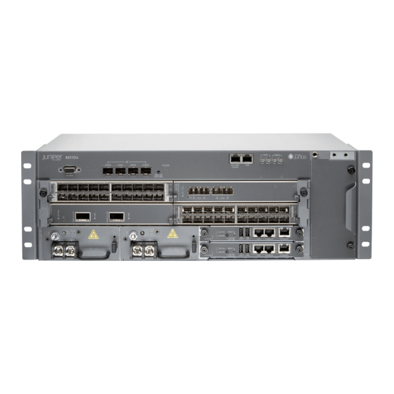
- Page 9 Figure 1: Front Panel of the MX104 Router ....... .
- Page 10 Figure 27: Removing the MX104 Air Filter ....... . 90...
- Page 11 Table 8: MX104 Routing Engine Buttons ....... . . 22...
- Page 12 Table 27: Power Consumed by MX104 Routers ......164 Table 28: MX104 FRU Power Requirements ......165 Table 29: Sample Power Requirements for an MX104 Router .
-
Page 13: About The Documentation
Junos OS Release Notes. ® To obtain the most current version of all Juniper Networks technical documentation, see the product documentation page on the Juniper Networks website at http://www.juniper.net/techpubs/ Documentation Conventions Table 1 on page xiii defines the notice icons used in this guide. -
Page 14: Table 2: Text And Syntax Conventions
MX104 3D Universal Edge Router Hardware Guide Table 2: Text and Syntax Conventions Convention Description Examples Bold text like this Represents text that you type. To enter configuration mode, type the configure command: user@host> configure Fixed-width text like this Represents output that appears on the user@host>... -
Page 15: Documentation Feedback
7 days a week, 365 days a year. Self-Help Online Tools and Resources For quick and easy problem resolution, Juniper Networks has designed an online self-service portal called the Customer Support Center (CSC) that provides you with the following features: Find CSC offerings: http://www.juniper.net/customers/support/... -
Page 16: Opening A Case With Jtac
Download the latest versions of software and review release notes: http://www.juniper.net/customers/csc/software/ Search technical bulletins for relevant hardware and software notifications: https://www.juniper.net/alerts/ Join and participate in the Juniper Networks Community Forum: http://www.juniper.net/company/communities/ Open a case online in the CSC Case Management tool: http://www.juniper.net/cm/... -
Page 17: Mx104 3D Universal Edge Router Overview
PART 1 MX104 3D Universal Edge Router Overview MX104 Router Description on page 3 MX104 Hardware Components on page 11 Protocols and Applications Supported by the Router on page 27 Copyright © 2014, Juniper Networks, Inc. - Page 18 MX104 3D Universal Edge Router Hardware Guide Copyright © 2014, Juniper Networks, Inc.
-
Page 19: Mx104 Router Description
MX104 Port and Interface Numbering on page 5 MX104 3D Universal Edge Router Overview The Juniper Networks MX104 3D Universal Edge Router is optimized for aggregating mobile, enterprise WAN, business, and residential access services. The MX104 router is designed for high-density access and pre-aggregation and is environmentally hardened to allow outside deployments in cabinets and remote terminals. -
Page 20: Mx104 Hardware And Cli Terminology Mapping
Documentation MX104 Port and Interface Numbering on page 5 MX104 Chassis Overview on page 11 Protocols and Applications Supported by MX104 Routers on page 27 MX104 Hardware and CLI Terminology Mapping The MX104 router supports the components in Table 3 on page 4, listed in alphabetic order. -
Page 21: Mx104 Port And Interface Numbering
Identifying Interface Numbers on the Hardware on page 5 Identifying Interface Numbers in the CLI on page 7 Identifying Interface Numbers on the Hardware Each MX104 router has three built-in MPCs, which are represented in the CLI as FPC 0 through . -
Page 22: Figure 3: Mx104 Interface Port Mapping Example
MX104 3D Universal Edge Router Hardware Guide Figure 3: MX104 Interface Port Mapping Example MPC 0 and MPC 1 have two slots each that accept MICs. The MICs are represented as in the CLI and are logically divided into PICs depending on their type. A... -
Page 23: Identifying Interface Numbers In The Cli
Ethernet interface For a complete list of media types, see Interface Naming Overview. fpc—Slot in which the MPC is installed. On the MX104 router, the three MPCs are built into the chassis and are represented in the CLI as... - Page 24 MX104 3D Universal Edge Router Hardware Guide Hardware inventory: Item Version Part number Serial number Description Chassis G3498 MX104 Midplane REV 28 750-044219 CAAX5767 MX104 PEM 0 REV 03 740-045932 1H073050110 DC Power Entry Module PEM 1 REV 03 740-045932...
- Page 25 Chapter 1: MX104 Router Description ge-1/0/2.0 inet 10.0.2.10/24 multiservice ge-1/0/3 ge-1/0/3.0 inet 10.0.3.10/24 multiservice ge-1/0/4 ge-1/0/4.0 inet 10.0.4.10/24 multiservice ge-1/0/5 ge-1/0/5.0 inet 10.0.5.10/24 multiservice ge-1/0/6 ge-1/0/6.0 inet 10.0.6.10/24 multiservice ge-1/0/7 ge-1/0/7.0 inet 10.0.7.10/24 multiservice ge-1/0/8 ge-1/0/8.0 inet 10.0.8.10/24 multiservice ge-1/0/9 ge-1/0/9.0...
- Page 26 MX104 3D Universal Edge Router Overview on page 3 Documentation MX104 Hardware and CLI Terminology Mapping on page 4 MX104 Chassis Overview on page 11 Protocols and Applications Supported by MX104 Routers on page 27 Copyright © 2014, Juniper Networks, Inc.
-
Page 27: Mx104 Hardware Components
MX104 Routing Engine Overview on page 20 MX104 LEDs Overview on page 23 MX104 Chassis Overview The MX104 router contains a front panel with slots in which you can install field-replaceable units (FRUs). From the front of the chassis, you can see the following components (see... -
Page 28: Mx104 Alarm Contact Port Overview
D-type connector. The external alarm contact has 15 pins that accept a single core wire from external alarm devices. A DE-15 alarm cable is required to connect the MX104 router to external alarm devices. Use the gauge wire appropriate for the external device that you are connecting. -
Page 29: Figure 5: Sample Output Alarm-Reporting Device
Chapter 2: MX104 Hardware Components Closed [NC] through the CLI. Contact 2 of each alarm functions as a reference [REF] or negative potential terminal for Contact 1 of the corresponding alarm and provides a current path for external alarm devices. -
Page 30: Mx104 Clocking And Timing Ports Overview
Packet (IEEE 1588-2008) v2 timing includes: Timing input when configured as Ordinary Clock (OC) or Boundary Clock (BC) Timing output when configured as BC Related Connecting the MX104 Router to External Clocking and Timing Devices on page 61 Documentation Copyright © 2014, Juniper Networks, Inc. -
Page 31: Mx104 Cooling System And Airflow Overview
MX104 1-PPS and 10-MHz GPS Port Specifications on page 176 MX104 Time of Day Port Specifications on page 176 MX104 Cooling System and Airflow Overview The cooling system in an MX104 router consists of the following components (see Figure 7 on page 15):... -
Page 32: Mx104 Modular Interface Card (Mic) Overview
MIC LEDs on page 18 Front-Pluggable MICs Modular Interface Cards (MICs) install into four slots in the front of the MX104 router and provide the physical connections to various network media types. MICs are hot-removable and hot-insertable. The slots are labeled , and . -
Page 33: Built-In 10-Gigabit Ethernet Mic
MX Series Interface Module Reference Built-in 10-Gigabit Ethernet MIC The built-in 10-Gigabit Ethernet MIC is fixed on the MX104 router. The MIC is labeled and is located on the front panel. The built-in 10-Gigabit Ethernet MIC has the following components:... -
Page 34: Mic Leds
Replacing an MX104 MIC on page 93 Maintaining the MX104 MICs and Network Ports on page 73 MX104 Power Overview The MX104 router uses either AC or DC power supplies (see Figure 9 on page 19 Figure 10 on page 20). -
Page 35: Ac Power Supplies
Chapter 2: MX104 Hardware Components Redundant power supplies are hot-removable and hot-insertable. When you remove a power supply from a router that uses only one power supply, the router might shut down depending on your configuration. AC Power Supplies on page 19... -
Page 36: Power Supply Leds
Related Connecting AC Power Cords to the MX104 Router on page 53 Documentation Connecting DC Power Cables to the MX104 Router on page 54 MX104 AC Power Specifications on page 159... -
Page 37: Mx104 Routing Engine Components
If the master Routing Engine fails or is removed and the backup is configured appropriately, the backup takes over as the master. The backup Routing Engine is hot-insertable and hot-removable. The MX104 router supports the Routing Engine with model number RE-MX104. Figure 11: MX104 Routing Engine MX104 Routing Engine Components on page 21... -
Page 38: Mx104 Routing Engine Buttons
MX104 3D Universal Edge Router Hardware Guide Two USB ports—Provides a removable media interface through which you can install the Junos OS manually. Junos OS supports USB version 1.0. Online/Offline button—Takes the Routing Engine online or offline when pressed (see “MX104 Routing Engine Buttons”... -
Page 39: Mx104 Boot Sequence
The port is not receiving data. MX104 Boot Sequence The MX104 router ships with Junos OS preinstalled and ready to be configured when the router is powered on. One eight-GB internal NAND Flash memory ( ) acts as the hard drive. -
Page 40: System Led On The Front Panel
MX104 3D Universal Edge Router Hardware Guide Figure 12: Alarm LEDs on the MX104 Router Table 11 on page 24 describes the alarm LED in more detail. Table 11: Alarm LEDs on the Front Panel Shape Color State LED Control Name... -
Page 41: Mic Leds
Three LEDs indicate the status of the Routing Engine. For more information, see “MX104 Routing Engine LEDs” on page Related Troubleshooting Resources for MX104 Routers on page 79 Documentation MX104 Chassis Overview on page 11 Copyright © 2014, Juniper Networks, Inc. - Page 42 MX104 3D Universal Edge Router Hardware Guide Copyright © 2014, Juniper Networks, Inc.
-
Page 43: Protocols And Applications Supported By The Router
Protocols and Applications Supported by MX104 Routers Table 13 on page 27 contains the first Junos OS Release support for protocols and applications on MX104 routers. A dash indicates that the protocol or application is not supported. Table 13: Protocols and Applications Supported by MX104 Routers... - Page 44 MX104 3D Universal Edge Router Hardware Guide Table 13: Protocols and Applications Supported by MX104 Routers (continued) Protocol or Application MX104 Static routes 13.2R2 OSPF 13.2R2 IS-IS 13.2R2 Border Gateway Protocol (BGP) 13.2R2 Internet Control Message Protocol (ICMP) 13.2R2 IPv6 13.2R2...
-
Page 45: Protocols And Applications Supported By The Router
Chapter 3: Protocols and Applications Supported by the Router Table 13: Protocols and Applications Supported by MX104 Routers (continued) Protocol or Application MX104 Pseudowire Emulation Edge to Edge (PWE3 [signaled]) 13.2R2 Static Ethernet PWs 13.2R2 Layer 2 Circuits 13.2R2 IEEE 802.3ag CC monitoring on active and standby pseudowires 13.2R2... - Page 46 MX104 3D Universal Edge Router Hardware Guide Table 13: Protocols and Applications Supported by MX104 Routers (continued) Protocol or Application MX104 Class Based Forwarding 13.2R2 Traffic Policing 13.2R2 per logical interface per physical interface per family Tricolor Marking Policers 13.2R2...
- Page 47 Chapter 3: Protocols and Applications Supported by the Router Table 13: Protocols and Applications Supported by MX104 Routers (continued) Protocol or Application MX104 Building-integrated timing supply (BITS) 13.2R2 Clock synchronization 13.2R2 Redundant clock (multiple 1588 masters) – OAM, Troubleshooting, Manageability, Lawful Intercept 13.2R2...
- Page 48 MX104 3D Universal Edge Router Hardware Guide Table 13: Protocols and Applications Supported by MX104 Routers (continued) Protocol or Application MX104 RADIUS Authentication 13.2R2 Control plane DOS prevention 13.2R2 High Availability Features MPLS FRR 13.2R2 Graceful Routing Engine Switchover (GRES) 13.2R2...
- Page 49 IP-IP unicast tunneling Multicast Tunnels Protocol Independent Multicast Tunnels (PIM) sparse mode unicast tunneling Virtual Loopback Tunnels (VT) Related MX104 3D Universal Edge Router Overview on page 3 Documentation MICs Supported by MX Series Routers Copyright © 2014, Juniper Networks, Inc.
- Page 50 MX104 3D Universal Edge Router Hardware Guide Copyright © 2014, Juniper Networks, Inc.
-
Page 51: Setting Up The Mx104 Router
Unpacking the MX104 Router on page 45 Installing the MX104 Router on page 49 Grounding and Providing Power to the MX104 Router on page 51 Connecting the MX104 Router to External Devices on page 59 Configuring Junos OS on page 65... - Page 52 MX104 3D Universal Edge Router Hardware Guide Copyright © 2014, Juniper Networks, Inc.
-
Page 53: Preparing The Site For Mx104 Router Installation
CHAPTER 4 Preparing the Site for MX104 Router Installation Preparing the Site for the MX104 Router Overview on page 37 Rack Requirements for MX104 Routers on page 38 Cabinet Requirements for MX104 Routers on page 39 Clearance Requirements for Airflow and Hardware Maintenance on MX104... -
Page 54: Rack Requirements For Mx104 Routers
Plan the cable routing and management. See “Maintaining Cables That Connect to MX104 Network Ports” on page Related Installing and Connecting an MX104 Router Overview on page 43 Documentation Rack Requirements for MX104 Routers You can mount the router on two-post racks or four-post racks. -
Page 55: Cabinet Requirements For Mx104 Routers
Related Cabinet Requirements for MX104 Routers on page 39 Documentation Installing and Connecting an MX104 Router Overview on page 43 Cabinet Requirements for MX104 Routers You can mount the router in a cabinet that contains a 19-in. (48.3 cm) rack. -
Page 56: Clearance Requirements For Airflow And Hardware Maintenance On Mx104
A cabinet larger than the minimum required provides better airflow and reduces the chance of overheating. Related Preparing the Site for the MX104 Router Overview on page 37 Documentation Rack Requirements for MX104 Routers on page 38 Clearance Requirements for Airflow and Hardware Maintenance on MX104 Routers... -
Page 57: Routers
Front for maintenance Related Preparing the Site for the MX104 Router Overview on page 37 Documentation Rack Requirements for MX104 Routers on page 38 Cabinet Requirements for MX104 Routers on page 39 Installing and Connecting an MX104 Router Overview on page 43... - Page 58 MX104 3D Universal Edge Router Hardware Guide Copyright © 2014, Juniper Networks, Inc.
-
Page 59: Mx104 Router Installation Overview
Connect the router to external devices. See: Connecting the MX104 Router to Management Devices on page 59 Connecting the MX104 Router to External Clocking and Timing Devices on page 61 Connecting the MX104 Router to an External Alarm-Reporting Device on page 62 Connect power to the router: AC-powered models—See... - Page 60 MX104 3D Universal Edge Router Hardware Guide Copyright © 2014, Juniper Networks, Inc.
-
Page 61: Unpacking The Mx104 Router
Unpacking an MX104 Router on page 47 Parts Inventory (Packing List) for an MX104 Router The MX104 routers are shipped in a cardboard carton, secured with foam packing material. The carton also contains an accessory box. The router shipment includes a packing list. Check the parts you receive in the router shipping carton against the items on the packing list. -
Page 62: Table 17: Accessory Box Parts List For An Mx104 Router
MX104 3D Universal Edge Router Hardware Guide Table 16: Parts List for a Fully Configured MX104 Router (continued) Component Quantity Blank panels for slots without components installed One blank panel for each slot not occupied by a component Table 17: Accessory Box Parts List for an MX104 Router... -
Page 63: Unpacking An Mx104 Router
Chapter 6: Unpacking the MX104 Router Unpacking an MX104 Router The MX104 routers are shipped in a cardboard carton, secured with foam packing material. The carton also contains an accessory box. CAUTION: MX104 routers are maximally protected inside the shipping carton. - Page 64 MX104 3D Universal Edge Router Hardware Guide Copyright © 2014, Juniper Networks, Inc.
-
Page 65: Installing The Mx104 Router
CHAPTER 7 Installing the MX104 Router Installing the MX104 Router in the Rack on page 49 Installing the MX104 Router in the Rack NOTE: The router can be installed horizontally in a rack or cabinet. To install the router in the rack (see... -
Page 66: Figure 14: Install The Front-Mounted Router In The Rack
3— Mounting screws 2—MX104 router Related Preparing the Site for the MX104 Router Overview on page 37 Documentation Installing and Connecting an MX104 Router Overview on page 43 Connecting the MX104 Router to Earth Ground on page 51 Copyright © 2014, Juniper Networks, Inc. -
Page 67: Grounding And Providing Power To The Mx104 Router
MX104 Router Connecting the MX104 Router to Earth Ground on page 51 Connecting AC Power Cords to the MX104 Router on page 53 Connecting DC Power Cables to the MX104 Router on page 54 Connecting the MX104 Router to Earth Ground... -
Page 68: Figure 15: Grounding Points On The Mx104 Router
Figure 15: Grounding Points on the MX104 Router 1— Grounding cable lug 2— Screws Related Installing and Connecting an MX104 Router Overview on page 43 Documentation Connecting AC Power Cords to the MX104 Router on page 53 Copyright © 2014, Juniper Networks, Inc. -
Page 69: Connecting Ac Power Cords To The Mx104 Router
Chapter 8: Grounding and Providing Power to the MX104 Router Connecting DC Power Cables to the MX104 Router on page 54 Preventing Electrostatic Discharge Damage to an MX104 Router on page 120 Connecting AC Power Cords to the MX104 Router... -
Page 70: Connecting Dc Power Cables To The Mx104 Router
Related MX104 Power Overview on page 18 Documentation MX104 AC Power Electrical Safety Guidelines and Warnings on page 141 MX104 AC Power Specifications on page 159 Connecting DC Power Cables to the MX104 Router To connect power to the router, you need the following tools:... -
Page 71: Figure 17: Connecting The Ground Cable To The Mx104 Dc Power Supply
Remove the nut and washer from the grounding point on the power supply. Secure each grounding cable lug to the grounding point with the washer and nut. Figure 17: Connecting the Ground Cable to the MX104 DC Power Supply Remove the plastic cover protecting the terminal on the faceplate. - Page 72 MX104 3D Universal Edge Router Hardware Guide Secure each power cable lug to the terminal with the washers and screw (see Figure 18 on page 57). Apply 27.4 lb-in. (3.1 Nm) of torque to each screw. Do not overtighten the screw. (Use a number 2 Phillips screwdriver.) a.
-
Page 73: Figure 18: Connecting Dc Power To The Router
Chapter 8: Grounding and Providing Power to the MX104 Router Figure 18: Connecting DC Power to the Router Related MX104 Power Overview on page 18 Documentation Installing and Connecting an MX104 Router Overview on page 43 Connecting the MX104 Router to Earth Ground on page 51... - Page 74 MX104 3D Universal Edge Router Hardware Guide Copyright © 2014, Juniper Networks, Inc.
-
Page 75: Connecting The Mx104 Router To External Devices
Devices Connecting the MX104 Router to Management Devices on page 59 Connecting the MX104 Router to External Clocking and Timing Devices on page 61 Connecting the MX104 Router to an External Alarm-Reporting Device on page 62 Connecting Interface Cables to MX104 Routers on page 63... -
Page 76: Connecting The Router To A Management Console Device
MX104 3D Universal Edge Router Hardware Guide Figure 20: Ethernet Port MGMT port Management PC Management network Connecting the Router to a Management Console Device You can connect a console, laptop, modem, or other auxiliary device by connecting a serial cable to the port on the front panel labeled CONSOLE . -
Page 77: Connecting The Mx104 Router To External Clocking And Timing Devices
E1 line timing sources, and external inputs. Connecting 1-PPS and 10-MHz Timing Devices to the MX104 Router on page 61 Connecting a T1 or E1 External Clocking Device to the MX104 Router on page 61 Connecting a Time-of-Day Device to the MX104 Router on page 62... -
Page 78: Connecting A Time-Of-Day Device To The Mx104 Router
Verify that the LEDs for the TOD port on the router are lit steadily green. Configure the port. See Configuring Clock Synchronization Interface on MX Series Routers. Related MX104 Clocking and Timing Ports Overview on page 14 Documentation MX104 Time of Day Port Specifications on page 176... -
Page 79: Connecting Interface Cables To Mx104 Routers
Chapter 9: Connecting the MX104 Router to External Devices wires into the slots in the front of the block based on the wiring for the external device. Tighten the screws to secure the wire. Orient the terminal block according to the labels to the left of the appropriate relay contact ( means “normally closed,... -
Page 80: Figure 23: Attaching A Cable To A Mic
Figure 23: Attaching a Cable to a MIC Fiber-optic cable Related Installing and Connecting an MX104 Router Overview on page 43 Documentation Connecting the MX104 Router to Management Devices on page 59 Initially Configuring the MX104 Router on page 65... -
Page 81: Configuring Junos Os
Initially Configuring the MX104 Router on page 65 Initially Configuring the MX104 Router The MX104 router ships with Junos OS preinstalled and ready to be configured when the router is powered on. One 8-GB internal NAND Flash memory ( ) acts as the hard drive. - Page 82 MX104 3D Universal Edge Router Hardware Guide This procedure connects the router to the network but does not enable it to forward traffic. For complete information about enabling the router to forward traffic, including examples, see the Junos OS configuration guides.
- Page 83 (Optional) Display the configuration to verify that it is correct. [edit] root@# show system { host-name host-name; domain-name domain-name; backup-router address; root-authentication { authentication-method (password | public-key); name-server { address; interfaces { fxp0 { unit 0 { family inet { address address/prefix-length; Copyright © 2014, Juniper Networks, Inc.
- Page 84 When you have finished configuring the router, exit configuration mode. [edit] root@host# exit root@host> Related MX104 Hardware and CLI Terminology Mapping on page 4 Documentation Protocols and Applications Supported by MX104 Routers on page 27 Copyright © 2014, Juniper Networks, Inc.
-
Page 85: Hardware Maintenance, Troubleshooting, And Replacement Procedures
PART 3 Hardware Maintenance, Troubleshooting, and Replacement Procedures Maintaining MX104 Router Hardware Components on page 71 Troubleshooting MX104 Hardware Components on page 79 Replacing MX104 Hardware Components on page 83 Copyright © 2014, Juniper Networks, Inc. - Page 86 MX104 3D Universal Edge Router Hardware Guide Copyright © 2014, Juniper Networks, Inc.
-
Page 87: Maintaining Mx104 Router Hardware Components
Components Routine Maintenance Procedures for the MX104 Router on page 71 Maintaining Cables That Connect to MX104 Network Ports on page 71 Maintaining the MX104 MICs and Network Ports on page 73 Maintaining the MX104 Cooling System on page 73... - Page 88 Use only an approved alcohol-free fiber-optic cable cleaning kit, such as the Opptex Cletop-S Fiber Cleaner. Follow the directions for the cleaning kit you use. Related Routine Maintenance Procedures for the MX104 Router on page 71 Documentation Troubleshooting Resources for MX104 Routers on page 79...
-
Page 89: Maintaining The Mx104 Mics And Network Ports
For further description of the output from the command, see the show chassis fpc command summary in the CLI Explorer Related MX104 Hardware and CLI Terminology Mapping on page 4 Documentation Maintaining the MX104 Cooling System Purpose For optimum cooling, verify the condition of the fans. -
Page 90: Maintaining The Mx104 Air Filter
For further description of the output from the command, see the show chassis environment command summary in the CLI Explorer Related MX104 Cooling System and Airflow Overview on page 15 Documentation Replacing an MX104 Fan Tray on page 91 Maintaining the MX104 Air Filter Purpose For optimum cooling, verify the condition of the air filter. -
Page 91: Maintaining The Mx104 Power System
Related Replacing an MX104 Air Filter on page 89 Documentation Routine Maintenance Procedures for the MX104 Router on page 71 Maintaining the MX104 Power System Purpose For optimum performance, verify the condition of the power supplies and grounding. -
Page 92: Maintaining The Mx104 Routing Engines
MX104 3D Universal Edge Router Hardware Guide MX104 Power Overview on page 18 Maintaining the MX104 Routing Engines Purpose For optimum router performance, verify the condition of the Routing Engines. Action On a regular basis: Check the Routing Engine LEDs. For more information about the LEDs and the display, “MX104 Routing Engine LEDs”... - Page 93 Chapter 11: Maintaining MX104 Router Hardware Components Meaning The command output displays the Routing Engine slot number, current state ( Master , or ), election priority ( ), and airflow temperature. The Backup Disabled Master Backup command output also displays the total DRAM available to the Routing Engine processor, the CPU utilization percentage, and the Routing Engine serial number for the slot.
- Page 94 MX104 3D Universal Edge Router Hardware Guide Copyright © 2014, Juniper Networks, Inc.
-
Page 95: Troubleshooting Mx104 Hardware Components
Components Troubleshooting Resources for MX104 Routers on page 79 Understanding Alarm Types and Severity Classes on MX104 Routers on page 80 Verifying Active Alarms on MX104 Routers on page 81 Monitoring System Log Messages on MX104 Routers on page 82... -
Page 96: Alarm Devices And Messages
Related Understanding Alarm Types and Severity Classes on MX104 Routers on page 80 Documentation Verifying Active Alarms on MX104 Routers on page 81 Monitoring System Log Messages on MX104 Routers on page 82... -
Page 97: Alarm Severity Classes
Monitoring System Log Messages on MX104 Routers on page 82 Verifying Active Alarms on MX104 Routers Purpose Use the monitoring functionality to view alarm information for the MX104 routers, including alarm type, alarm severity, and a brief description for each active alarm on the router. Action Observe the system LED on the front panel of the router. -
Page 98: Monitoring System Log Messages On Mx104 Routers
Alarm severity—either major or minor Description Brief synopsis of the alarm Related Understanding Alarm Types and Severity Classes on MX104 Routers on page 80 Documentation Monitoring System Log Messages on MX104 Routers on page 82 Monitoring System Log Messages on MX104 Routers Purpose Use the monitoring functionality to view system log messages for MX Series routers. -
Page 99: Replacing Mx104 Hardware Components
Table 20 on page 84 lists the FRUs for the MX104 router. Before you replace a Routing Engine, you must take the Routing Engine offline. Copyright © 2014, Juniper Networks, Inc. -
Page 100: Replacing Mx104 Cables
Replacing an MX104 Alarm Cable Disconnecting the Router from an External Alarm-Reporting Device on page 84 Connecting the MX104 Router to an External Alarm-Reporting Device on page 85 Disconnecting the Router from an External Alarm-Reporting Device Ensure that you have the following parts and tools available: Electrostatic discharge (ESD) grounding strap 2.5-mm flat-blade (–) screwdriver... -
Page 101: Device
If attaching a reporting device for the other kind of alarm, repeat the procedure. Replacing an MX104 Clocking or Timing Cable Removing an MX104 Clocking or Timing Cable on page 85 Installing an MX104 Clocking or Timing Cable on page 86... -
Page 102: Installing An Mx104 Clocking Or Timing Cable
Replacing an MX104 Console or Auxiliary Cable NOTE: port is not supported. Removing an MX104 Console or Auxiliary Cable on page 86 Installing an MX104 Console or Auxiliary Cable on page 86 Removing an MX104 Console or Auxiliary Cable To remove a serial cable connected to a console or auxiliary device: Attach an ESD grounding strap to your bare wrist and connect the strap to one of the ESD points on the chassis. -
Page 103: Replacing An Mx104 Management Ethernet Cable
Disconnecting an MX104 Fiber-Optic Cable on page 87 Connecting an MX104 Fiber-Optic Cable on page 88 Disconnecting an MX104 Fiber-Optic Cable The MX104 router has field-replaceable unit (FRU) optical transceivers to which you can connect fiber-optic cables. Copyright © 2014, Juniper Networks, Inc. -
Page 104: Connecting An Mx104 Fiber-Optic Cable
MX104 3D Universal Edge Router Hardware Guide Before you begin disconnecting a fiber-optic cable from an optical transceiver installed in an MX104 router, ensure that you have taken the necessary precautions for safe handling of lasers (see “Laser Safety Warnings for Juniper Networks Devices” on page 128). -
Page 105: Replacing An Mx104 Air Filter
Replacing an MX104 Air Filter Removing an MX104 Air Filter on page 89 Installing an MX104 Air Filter on page 90 Removing an MX104 Air Filter... -
Page 106: Installing An Mx104 Air Filter
MX104 3D Universal Edge Router Hardware Guide The air filter must be installed on the right side of the fan tray. To remove the air filter (see Figure 27 on page 90): Attach an ESD grounding strap to your bare wrist and connect the strap to one of the ESD points on the chassis. -
Page 107: Replacing An Mx104 Fan Tray
Chapter 13: Replacing MX104 Hardware Components Figure 28: Installing the Air Filter Related MX104 Cooling System and Airflow Overview on page 15 Documentation Replacing an MX104 Fan Tray Removing an MX104 Fan Tray on page 91 Installing an MX104 Fan Tray on page 92... -
Page 108: Installing An Mx104 Fan Tray
Tighten the captive screws on the fan tray faceplate to secure it in the chassis. Figure 30: Installing the Fan Tray Related MX104 Cooling System and Airflow Overview on page 15 Documentation Replacing an MX104 Air Filter on page 89... -
Page 109: Replacing An Mx104 Mic
MICs are hot-insertable and hot-removable. When you remove a MIC, the router continues to function, although the MIC interfaces being removed no longer function. In the MX104 router, the MICs can be installed in four slots in the front of the router. A MIC weighs less than 2 lb (0.9 kg). -
Page 110: Installing An Mx104 Mic
MX104 3D Universal Edge Router Hardware Guide CAUTION: Avoid bending fiber-optic cable beyond its minimum bend radius. An arc smaller than a few inches in diameter can damage the cable and cause problems that are difficult to diagnose. Loosen the captive screw on the cover that is adjacent to the MIC that you are removing. -
Page 111: Figure 32: Installing A Mic
The normal functioning status LED confirms that the MIC is online. You can also verify correct MIC functioning by issuing the command described show chassis fpc pic-status “Maintaining the MX104 MICs and Network Ports” on page Figure 32: Installing a MIC Copyright © 2014, Juniper Networks, Inc. -
Page 112: Replacing An Mx104 Ac Power Supply
Related MX104 Modular Interface Card (MIC) Overview on page 16 Documentation Maintaining Cables That Connect to MX104 Network Ports on page 71 Replacing an MX104 AC Power Supply Removing an MX104 AC Power Supply on page 96 Installing an MX104 AC Power Supply on page 97... -
Page 113: Installing An Mx104 Ac Power Supply
Chapter 13: Replacing MX104 Hardware Components Figure 33: Removing an AC Power Cord Figure 34: Removing an AC Power Supply Installing an MX104 AC Power Supply To install an AC power supply (see Figure 35 on page 98): Attach an ESD grounding strap to your bare wrist and connect the strap to one of the ESD points on the chassis. -
Page 114: Replacing An Mx104 Dc Power Supply
MX104 3D Universal Edge Router Hardware Guide Figure 35: Installing an AC Power Supply Related Connecting AC Power Cords to the MX104 Router on page 53 Documentation MX104 AC Power Specifications on page 159 MX104 AC Power Cord Specifications on page 160... - Page 115 Chapter 13: Replacing MX104 Hardware Components CAUTION: To maintain proper cooling and prevent thermal shutdown of the operating power supply unit, each power supply slot must contain either a power supply or a blank panel. If you remove a power supply, you must install a replacement power supply or a blank panel shortly after the removal.
-
Page 116: Figure 36: Disconnecting The Dc Power Cables
MX104 3D Universal Edge Router Hardware Guide Figure 36: Disconnecting the DC Power Cables Figure 37: Disconnecting the Grounding Cable Figure 38: Removing a DC Power Supply Copyright © 2014, Juniper Networks, Inc. -
Page 117: Installing An Mx104 Dc Power Supply
Chapter 13: Replacing MX104 Hardware Components Installing an MX104 DC Power Supply WARNING: Before performing DC power procedures, ensure that power is removed from the DC circuit. To ensure that all power is off, locate the circuit breaker on the panel board that services the DC circuit, switch the circuit breaker to the off position, and tape the switch handle of the circuit breaker in the off position. -
Page 118: Figure 39: Connecting A Dc Power Supply Grounding Cable
MX104 3D Universal Edge Router Hardware Guide Figure 39: Connecting a DC Power Supply Grounding Cable Remove the screws and washers from the DC terminals. Verify that the DC power cables are correctly labeled before making connections to the power supply. In a typical power distribution scheme where the return is connected... -
Page 119: Figure 40: Installing A Dc Power Supply
Chapter 13: Replacing MX104 Hardware Components CAUTION: The maximum torque rating of the terminal screws on the DC power supply is 27.4 lb-in. (3.1 Nm). The terminal screws may be damaged if excessive torque is applied. Use only a torque-controlled driver to tighten screws on the DC power supply terminals. -
Page 120: Replacing An Mx104 Routing Engine
MX104 Router Grounding Specifications on page 157 MX104 DC Power Electrical Safety Guidelines on page 142 DC Power Electrical Safety Warnings for Juniper Networks Devices on page 143 MX104 DC Power Specifications on page 162 MX104 DC Power Cable and Lug Specifications on page 163... -
Page 121: Table 21: Effect Of Taking The Routing Engine Offline
Chapter 13: Replacing MX104 Hardware Components Table 21 on page 105 explains the effect of taking the Routing Engine offline. Table 21: Effect of Taking the Routing Engine Offline Type of Routing Engine Effect of Taking the Routing Engine Offline Nonredundant Routing The router shuts down. -
Page 122: Taking An Mx104 Routing Engine Offline
MX104 3D Universal Edge Router Hardware Guide To configure Routing Engine-specific parameters and still use the same configuration on both Routing Engines, include the appropriate configuration statements under the statements at the [ ] hierarchy level and use the edit groups apply-groups statement. -
Page 123: Removing An Mx104 Routing Engine
Chapter 13: Replacing MX104 Hardware Components NOTE: The SCB might continue forwarding traffic for approximately five minutes after the command has been issued. request system halt Removing an MX104 Routing Engine Before you remove a Routing Engine, remove the cables that connect to it. -
Page 124: Installing An Mx104 Routing Engine
MX104 3D Universal Edge Router Hardware Guide Figure 42: Removing an MX104 Routing Engine Installing an MX104 Routing Engine To install a Routing Engine (see Figure 43 on page 109): Attach an ESD grounding strap to your bare wrist and connect the strap to one of the ESD points on the chassis. -
Page 125: Replacing An Mx104 Transceiver
Replacing an MX104 Transceiver Small form-factor pluggable transceivers (SFPs) are optical transceivers that are installed in the front panel of the MX104 router. Transceivers are hot-insertable and hot-removable. Removing an MX104 Transceiver on page 109 Installing an MX104 Transceiver on page 111... -
Page 126: Figure 44: Removing Transceivers
MX104 3D Universal Edge Router Hardware Guide WARNING: Do not look directly into a fiber-optic transceiver or into the ends of fiber-optic cables. Fiber-optic transceivers and fiber-optic cable connected to a transceiver emit laser light that can damage your eyes. -
Page 127: Installing An Mx104 Transceiver
For more information about the component LEDs, see the “MX104 LEDs Overview” on page Related MX104 Chassis Overview on page 11 Documentation MX104 Modular Interface Card (MIC) Overview on page 16 Maintaining the MX104 MICs and Network Ports on page 73 Copyright © 2014, Juniper Networks, Inc. - Page 128 MX104 3D Universal Edge Router Hardware Guide Copyright © 2014, Juniper Networks, Inc.
-
Page 129: Appendixes
PART 4 Appendixes Safety and Regulatory Compliance Information for the MX104 Router on page 115 MX104 Router Physical Specifications on page 153 MX104 Router Environmental Specifications on page 155 Power Guidelines, Requirements, and Specifications for the MX104 Router on page 157... - Page 130 MX104 3D Universal Edge Router Hardware Guide Copyright © 2014, Juniper Networks, Inc.
-
Page 131: Appendix A Safety And Regulatory Compliance Information For The Mx104 Router
APPENDIX A Safety and Regulatory Compliance Information for the MX104 Router Definition of Safety Warning Levels on page 115 Safety Guidelines and Warnings on page 117 Agency Approvals and Compliance Statements on page 147 Definition of Safety Warning Levels The documentation uses the following levels of safety warnings:... - Page 132 Installation Safety Warnings for Juniper Networks Devices on page 122 Maintenance and Operational Safety Warnings for Juniper Networks Devices General Electrical Safety Warnings for Juniper Networks Devices on page 136 DC Power Electrical Safety Warnings for Juniper Networks Devices on page 143 Copyright © 2014, Juniper Networks, Inc.
-
Page 133: Safety Guidelines And Warnings
Appendix A: Safety and Regulatory Compliance Information for the MX104 Router Safety Guidelines and Warnings General Safety Guidelines for Juniper Networks Devices on page 117 General Safety Warnings for Juniper Networks Devices on page 118 Preventing Electrostatic Discharge Damage to an MX104 Router on page 120... -
Page 134: General Safety Warnings For Juniper Networks Devices
Avoid touching uninsulated electrical wires or terminals that have not been disconnected from their power source. Such an action could cause electrical shock. Related General Safety Warnings for Juniper Networks Devices on page 118 Documentation General Safety Warnings for Juniper Networks Devices... - Page 135 Appendix A: Safety and Regulatory Compliance Information for the MX104 Router gained only by service personnel through the use of a special tool, lock and key, or other means of security, and which is controlled by the authority responsible for the location.
-
Page 136: Preventing Electrostatic Discharge Damage To An Mx104 Router
Maintenance and Operational Safety Warnings for Juniper Networks Devices General Electrical Safety Warnings for Juniper Networks Devices on page 136 DC Power Electrical Safety Warnings for Juniper Networks Devices on page 143 Preventing Electrostatic Discharge Damage to an MX104 Router Many router hardware components are sensitive to damage from static electricity. -
Page 137: Fire Safety Requirements For Juniper Networks Devices
Establish procedures for protecting people in a fire emergency, provide safety training, and properly provision fire-control equipment and fire extinguishers. In addition, establish procedures to protect your equipment in a fire emergency. Juniper Networks products should be installed in an environment suitable for electronic equipment. -
Page 138: Fire Suppression
To keep warranties effective, do not use a dry chemical fire extinguisher to control a fire at or near a Juniper Networks device. If a dry chemical fire extinguisher is used, the unit is no longer eligible for coverage under a service agreement. -
Page 139: Intra-Building Ports Warning
Appendix A: Safety and Regulatory Compliance Information for the MX104 Router Intra-Building Ports Warning WARNING: The intra-building ports of the equipment or subassembly are suitable for connection to intra-building or unexposed wiring or cabling only. The intra-building ports of the equipment or subassembly MUST NOT be metallically connected to interfaces that connect to the OSP or its wiring. - Page 140 MX104 3D Universal Edge Router Hardware Guide WARNING: To prevent bodily injury when mounting or servicing the chassis in a rack, take the following precautions to ensure that the system remains stable. The following directives help maintain your safety: The chassis must be installed into a rack that is secured to the building structure.
- Page 141 Appendix A: Safety and Regulatory Compliance Information for the MX104 Router Le rack sur lequel est monté le router doit être fixé à la structure du bâtiment. Si cette unité constitue la seule unité montée en casier, elle doit être placée dans le bas.
- Page 142 MX104 3D Universal Edge Router Hardware Guide Router må installeres i et stativ som er forankret til bygningsstrukturen. Denne enheten bør monteres nederst i kabinettet hvis dette er den eneste enheten i kabinettet. Ved montering av denne enheten i et kabinett som er delvis fylt, skal kabinettet lastes fra bunnen og opp med den tyngste komponenten nederst i kabinettet.
-
Page 143: Ramp Warning
Appendix A: Safety and Regulatory Compliance Information for the MX104 Router Router måste installeras i en ställning som är förankrad i byggnadens struktur. Om denna enhet är den enda enheten på ställningen skall den installeras längst ned på ställningen. Om denna enhet installeras på en delvis fylld ställning skall ställningen fyllas nedifrån och upp, med de tyngsta enheterna längst ned på... -
Page 144: General Laser Safety Guidelines For Juniper Networks Devices
General Safety Guidelines for Juniper Networks Devices on page 117 Documentation Installing and Connecting an MX104 Router Overview on page 43 General Laser Safety Guidelines for Juniper Networks Devices Devices with single-mode optical interfaces are equipped with laser transmitters, which are considered a Class 1 Laser Product by the U.S. -
Page 145: Class 1 Laser Product Warning
Appendix A: Safety and Regulatory Compliance Information for the MX104 Router Laser Beam Warning on page 130 Radiation from Open Port Apertures Warning on page 130 Class 1 Laser Product Warning WARNING: Class 1 laser product. Waarschuwing Klasse-1 laser produkt. -
Page 146: Laser Beam Warning
MX104 3D Universal Edge Router Hardware Guide Laser Beam Warning WARNING: Do not stare into the laser beam or view it directly with optical instruments. Waarschuwing Niet in de straal staren of hem rechtstreeks bekijken met optische instrumenten. Varoitus Älä katso säteeseen äläkä tarkastele sitä suoraan optisen laitteen avulla. -
Page 147: Maintenance And Operational Safety Warnings For Mx104 Routers
Appendix A: Safety and Regulatory Compliance Information for the MX104 Router Warnung Aus der Port-Öffnung können unsichtbare Strahlen emittieren, wenn kein Glasfaserkabel angeschlossen ist. Vermeiden Sie es, sich den Strahlungen auszusetzen, und starren Sie nicht in die Öffnungen! Avvertenza Quando i cavi in fibra non sono inseriti, radiazioni invisibili possono essere emesse attraverso l'apertura della porta. -
Page 148: Jewelry Removal Warning
MX104 3D Universal Edge Router Hardware Guide Waarschuwing Er is ontploffingsgevaar als de batterij verkeerd vervangen wordt. Vervang de batterij slechts met hetzelfde of een equivalent type dat door de fabrikant aanbevolen is. Gebruikte batterijen dienen overeenkomstig fabrieksvoorschriften weggeworpen te worden. - Page 149 Appendix A: Safety and Regulatory Compliance Information for the MX104 Router Waarschuwing Alvorens aan apparatuur te werken die met elektrische leidingen is verbonden, sieraden (inclusief ringen, kettingen en horloges) verwijderen. Metalen voorwerpen worden warm wanneer ze met stroom en aarde zijn verbonden, en kunnen ernstige brandwonden veroorzaken of het metalen voorwerp aan de aansluitklemmen lassen.
-
Page 150: Lightning Activity Warning
MX104 3D Universal Edge Router Hardware Guide allvarliga brännskador; metallobjekt kan också sammansvetsas med kontakterna. Lightning Activity Warning WARNING: Do not work on the system or connect or disconnect cables during periods of lightning activity. Waarschuwing Tijdens onweer dat gepaard gaat met bliksem, dient u niet aan het systeem te werken of kabels aan te sluiten of te ontkoppelen. -
Page 151: Product Disposal Warning
Appendix A: Safety and Regulatory Compliance Information for the MX104 Router Varoitus Ettei router-sarjan reititin ylikuumentuisi, sitä ei saa käyttää tilassa, jonka lämpötila ylittää korkeimman suositellun ympäristölämpötilan 65° C. Ettei ilmanvaihto estyisi, tuuletusaukkojen ympärille on jätettävä ainakin 15,2 cm tilaa. -
Page 152: General Electrical Safety Guidelines And Warnings
Devices on page 140 In Case of an Electrical Accident on page 141 MX104 AC Power Electrical Safety Guidelines and Warnings on page 141 MX104 DC Power Electrical Safety Guidelines on page 142 DC Power Electrical Safety Warnings for Juniper Networks Devices on page 143... - Page 153 Appendix A: Safety and Regulatory Compliance Information for the MX104 Router Multiple Power Supplies Disconnection Warning on page 138 Power Disconnection Warning on page 139 Grounded Equipment Warning WARNING: The network device is intended to be grounded. Ensure that the network device is connected to earth ground during normal use.
- Page 154 MX104 3D Universal Edge Router Hardware Guide Varoitus Laitetta asennettaessa on maahan yhdistäminen aina tehtävä ensiksi ja maadoituksen irti kytkeminen viimeiseksi. Attention Lors de l'installation de l'appareil, la mise à la terre doit toujours être connectée en premier et déconnectée en dernier.
- Page 155 Appendix A: Safety and Regulatory Compliance Information for the MX104 Router Warnung Diese Einheit verfügt über mehr als einen Stromanschluß; um Strom gänzlich von der Einheit fernzuhalten, müssen alle Stromzufuhren abgetrennt sein. Avvertenza Questa unità ha più di una connessione per alimentatore elettrico;...
-
Page 156: General Electrical Safety Guidelines And Electrical Codes For Juniper Networks Devices
Varning! Innan du arbetar med ett chassi eller nära strömförsörjningsenheter skall du för växelströmsenheter dra ur nätsladden och för likströmsenheter bryta strömmen vid överspänningsskyddet. Related DC Power Electrical Safety Warnings for Juniper Networks Devices on page 143 Documentation General Electrical Safety Guidelines and Electrical Codes for Juniper Networks Devices... -
Page 157: In Case Of An Electrical Accident
Appendix A: Safety and Regulatory Compliance Information for the MX104 Router Many router components can be removed and replaced without powering off or disconnecting power to the router. Never install equipment if it appears damaged. Related In Case of an Electrical Accident on page 141... -
Page 158: Mx104 Dc Power Electrical Safety Guidelines
MX104 AC Power Specifications on page 159 Documentation MX104 AC Power Cord Specifications on page 160 Connecting AC Power Cords to the MX104 Router on page 53 MX104 DC Power Electrical Safety Guidelines The following electrical safety guidelines apply to a DC-powered router: A DC-powered router is equipped with a DC terminal block that is rated for the power requirements of a maximally configured router. -
Page 159: Dc Power Electrical Safety Warnings For Juniper Networks Devices
Appendix A: Safety and Regulatory Compliance Information for the MX104 Router Ensure that the polarity of the DC input wiring is correct. Under certain conditions, connections with reversed polarity might trip the primary circuit breaker or damage the equipment. For personal safety, connect the green and yellow wire to safety (earth) ground at both the router and the supply side of the DC wiring. - Page 160 MX104 3D Universal Edge Router Hardware Guide the circuit breaker on the panel board that services the DC circuit, switch the circuit breaker to the off position, and tape the switch handle of the circuit breaker in the off position.
- Page 161 Appendix A: Safety and Regulatory Compliance Information for the MX104 Router asegurarse de que toda la alimentación esté cortada (OFF), localizar el interruptor automático en el panel que alimenta al circuito de corriente continua, cambiar el interruptor automático a la posición de Apagado (OFF), y sujetar con cinta la palanca del interruptor automático en posición de...
-
Page 162: Site Electrical Wiring Guidelines For Mx Series Routers
Related General Safety Warnings for Juniper Networks Devices on page 118 Documentation General Electrical Safety Warnings for Juniper Networks Devices on page 136 Site Electrical Wiring Guidelines for MX Series Routers Distance Limitations for Signaling on page 146 Radio Frequency Interference on page 146... -
Page 163: Agency Approvals And Compliance Statements
Appendix A: Safety and Regulatory Compliance Information for the MX104 Router Strong sources of electromagnetic interference (EMI) can destroy the signal drivers and receivers in the router and conduct power surges over the lines into the equipment, resulting in an electrical hazard. It is particularly important to provide a properly grounded and shielded environment and to use electrical surge-suppression devices. - Page 164 MX104 3D Universal Edge Router Hardware Guide IEC 60950-1 Information Technology Equipment—Safety - Part 1: General Requirements (with country deviations) EN 60825-1 Safety of Laser Products—Part 1: Equipment Classification, Requirements and User's Guide EMC: EN 300 386 V1.3.3 Telecom Network Equipment - EMC Requirements...
-
Page 165: Compliance Statements For Nebs For Mx104 Routers
Appendix A: Safety and Regulatory Compliance Information for the MX104 Router SR-3580 NEBS Criteria Levels (Level 3 Compliance) Related Compliance Statements for EMC Requirements for MX104 Routers on page 149 Documentation Compliance Statements for NEBS for MX104 Routers on page 149... -
Page 166: Declaration Of Conformity
MX104 3D Universal Edge Router Hardware Guide Declaration of Conformity This topic shows the Declaration of Conformity for the router. Figure 47: MX104 Declaration of Conformity Israel Class A מוצר זה הוא מוצר מוצר זה עלול לגרום הפרעות בתדר רדיו,ובמקרה זה ,המשתמש עשוי להידרש... -
Page 167: Japan
Appendix A: Safety and Regulatory Compliance Information for the MX104 Router Translation from Hebrew—This product is Class A. The product may cause radio interference, and in such a situation, the user may be required to take adequate measures Japan Translation from Japanese—This is a Class A product. In a domestic environment this product may cause radio interference in which case the user may be required to take adequate measures. - Page 168 Related Compliance Statements for NEBS for MX104 Routers on page 149 Documentation Compliance Statements for EMC Requirements for MX104 Routers on page 149 Compliance Statements for Environmental Requirements for Juniper Networks Devices on page 151 Copyright © 2014, Juniper Networks, Inc.
-
Page 169: Appendix Bmx104 Router Physical Specifications
MX104 Router Physical Specifications MX104 Router Physical Specifications on page 153 MX104 Router Physical Specifications The MX104 router is a rigid sheet-metal structure that houses the hardware components. Table 22 on page 153 summarizes the physical specifications of the MX104 router and its components. - Page 170 MX104 3D Universal Edge Router Hardware Guide Copyright © 2014, Juniper Networks, Inc.
-
Page 171: Appendix Cmx104 Router Environmental Specifications
APPENDIX C MX104 Router Environmental Specifications MX104 Router Environmental Specifications on page 155 MX104 Router Environmental Specifications The router must be installed in a rack or cabinet housed in a dry, clean, well-ventilated, and temperature-controlled environment. Ensure that these environmental guidelines are followed: The site must be as dust-free as possible, because dust can clog air intake vents and filters, reducing the efficiency of the router cooling system. - Page 172 Install the router only in restricted areas, such as dedicated equipment rooms and equipment closets, in accordance with Articles 110-16, 110-17, and 110-18 of the National Electrical Code, ANSI/NFPA 70. NOTE: The MX104 complies with GR3108 as Class-2 equipment. Related MX104 Router Physical Specifications on page 153 Documentation...
-
Page 173: Appendix D Power Guidelines, Requirements, And Specifications For The Mx104
MX104 AC Power Specifications on page 159 MX104 AC Power Cord Specifications on page 160 MX104 DC Power Specifications on page 162 MX104 DC Power Cable and Lug Specifications on page 163 MX104 Power Consumption on page 164 Power Requirements for MX104 Components on page 164... -
Page 174: Grounding Cable Lug Specifications
MX104 3D Universal Edge Router Hardware Guide Figure 48: Grounding Points on the MX104 Routers NOTE: All bare grounding connection points to the router must be cleaned and coated with an antioxidant solution before grounding the router. NOTE: All surfaces on the router that are unplated must be brought to a bright finish and treated with an antioxidant solution before connecting the router. -
Page 175: Grounding Cable Specifications
Appendix D: Power Guidelines, Requirements, and Specifications for the MX104 Router Figure 49: Grounding Cable Lug CAUTION: Before router installation begins, a licensed electrician must attach a cable lug to the grounding and power cables that you supply. A cable with an incorrectly attached lug can damage the router. -
Page 176: Mx104 Ac Power Cord Specifications
Related Connecting AC Power Cords to the MX104 Router on page 53 Documentation Replacing an MX104 AC Power Supply on page 96 MX104 AC Power Electrical Safety Guidelines and Warnings on page 141... -
Page 177: Table 25: Ac Power Cord Specifications
Appendix D: Power Guidelines, Requirements, and Specifications for the MX104 Router Table 25: AC Power Cord Specifications Country Model Number Electrical Specification Plug Type Design Standard Argentina CBL-PWR-C15M-HITEMP-AR 250 VAC, 10 A, 50 Hz RA/3 IRAM 2073 Australia CBL-PWR-C15M-HITEMP-AU 250 VAC, 10 A, 50 Hz... -
Page 178: Mx104 Dc Power Specifications
MX104 AC Power Electrical Safety Guidelines and Warnings on page 141 MX104 AC Power Specifications on page 159 MX104 DC Power Specifications The MX104 power supply contains DC power terminals to connect power to the router and supports the specifications shown in Table 26 on page 162. -
Page 179: Mx104 Dc Power Cable And Lug Specifications
Appendix D: Power Guidelines, Requirements, and Specifications for the MX104 Router without upgrading the power infrastructure, and allows the router to function at full capacity using multiple power supplies. Related Connecting DC Power Cables to the MX104 Router on page 54... -
Page 180: Dc Power Cable Specifications
DC Power Electrical Safety Warnings for Juniper Networks Devices on page 143 MX104 DC Power Specifications on page 162 MX104 Power Consumption The MX104 router supports installation of up to two AC or DC power supplies in slots labeled on the front of the router. Table 27 on page 164 lists the power consumed by the MX104 router. -
Page 181: Calculating Power Requirements For Mx104 Routers
Appendix D: Power Guidelines, Requirements, and Specifications for the MX104 Router Table 28: MX104 FRU Power Requirements Component Required Power (Watts) Fan tray 100 W For MIC power requirements, see MX Series Interface Module Reference AC power supply 600 W... -
Page 182: Table 29: Sample Power Requirements For An Mx104 Router
37 W Total output power 424 W NOTE: The power consumed by an MX104 router as shown in Table 29 on page 166, may differ slightly, due the power conversion losses in the power supply. Evaluate the power budget. In this step, we check the total output power against the maximum output power of available power supply options. -
Page 183: Table 31: Calculating Thermal Output
Appendix D: Power Guidelines, Requirements, and Specifications for the MX104 Router Table 31: Calculating Thermal Output Power Supply Thermal Output (BTUs per hour) MX104 power supply (as shown in the example) 431.3 W * 3.41 = 1471 BTU/hr MX104 power supply (maximum) 625 * 3.41 = 2131 BTU/hr... - Page 184 MX104 3D Universal Edge Router Hardware Guide Copyright © 2014, Juniper Networks, Inc.
-
Page 185: Appendix E Cable And Wire Guidelines For The Mx104 Router
APPENDIX E Cable and Wire Guidelines for the MX104 Router Understanding Fiber-Optic Cable Signal Loss, Attenuation, and Dispersion on page 169 Calculating Power Budget and Power Margin for Fiber-Optic Cables on page 170 Understanding Fiber-Optic Cable Signal Loss, Attenuation, and Dispersion... -
Page 186: Calculating Power Budget And Power Margin For Fiber-Optic Cables
MX104 3D Universal Edge Router Hardware Guide and single-mode transmission. An efficient optical data link must have enough light available to overcome attenuation. Dispersion is the spreading of the signal in time. The following two types of dispersion can affect an optical data link: Chromatic dispersion—Spreading of the signal in time resulting from the different... -
Page 187: Calculating Power Margin For Fiber-Optic Cable
Appendix E: Cable and Wire Guidelines for the MX104 Router = –15 dBm – (–28 dBm) = 13 dB Calculating Power Margin for Fiber-Optic Cable After calculating a link's power budget you can calculate the power margin (P ), which... - Page 188 MX104 3D Universal Edge Router Hardware Guide – LL = 13 dB – 2 km (1.0 dB/km) – 5 (0.5 dB) – 2 (0.5 dB) – 0.5 dB [HOL] – 1 dB [CRM] = 13 dB – 2 dB – 2.5 dB – 1 dB – 0.5 dB – 1 dB...
-
Page 189: Appendix Fmx104 Cable Connector Specifications
MX104 Time of Day Port Specifications on page 176 MX104 Routing Engine Ethernet Port Specifications on page 177 MX104 Routing Engine Auxiliary and Console Ports Specifications on page 179 MX104 Routing Engine USB Port Specifications on page 180 MX104 Alarm Contact Port Specifications... -
Page 190: Table 34: Alarm Contact Connector Pinouts
MX104 3D Universal Edge Router Hardware Guide Table 34 on page 174 shows the alarm contact connector pinouts. Table 34: Alarm Contact Connector Pinouts Number Signal Definition Direction CLI Port Mapping Function ALARM_IN0_NO/NC Input Input Alarm Port 0 External alarm input 0 (if voltage on this pin is... -
Page 191: Mx104 Bits Port Specifications
MX104 LEDs Overview on page 23 MX104 Alarm Contact Port Overview on page 12 Connecting the MX104 Router to an External Alarm-Reporting Device on page 62 MX104 BITS Port Specifications The external Building-Integrated Timing Supply (BITS) clock interface port labeled... -
Page 192: Mx104 1-Pps And 10-Mhz Gps Port Specifications
– Reserved – Related Connecting the MX104 Router to External Clocking and Timing Devices on page 61 Documentation MX104 1-PPS and 10-MHz GPS Port Specifications The router contains four ports that support 1-pulse-per-second (PPS) and 10-MHz GPS signals. These signals are internally isolated and have surge protection. -
Page 193: Port Pinouts
Reserved – Reserved – Related MX104 3D Universal Edge Router Overview on page 3 Documentation MX104 Chassis Overview on page 11 MX104 LEDs Overview on page 23 MX104 Clocking and Timing Ports Overview on page 14 MX104 Routing Engine Ethernet Port Specifications... -
Page 194: Cable Specifications
Cable Specifications Table 40 on page 178 lists the specifications for the cables that connect to the ETHERNET port. Table 40: MX104 Routing Engine Ethernet Port Cable Specifications Specification Value Cable specification Category 5 cable or equivalent suitable for 1000Base-T... -
Page 195: Mx104 Routing Engine Auxiliary And Console Ports Specifications
Cable Specifications on page 179 Pinouts on page 179 Cable Specifications Table 42 on page 179 lists the specifications for the cables that connect to console port. Table 42: MX104 Routing Engine Console Port Cable Specifications Specification Value Cable specification RS-232 (EIA-232) serial cable Cable/wire supplied One 6-ft (1.83-m) length with RJ-45/DB-9... -
Page 196: Mx104 Routing Engine Usb Port Specifications
Documentation Maintaining the MX104 Routing Engines on page 76 MX104 Routing Engine USB Port Specifications The following Juniper Networks USB Flash drives have been tested and are officially supported for the USB port on all MX Series routers: RE-USB-1G-S RE-USB-2G-S... -
Page 197: Appendix G Contacting Customer Support And Returning Mx104 Hardware
MX104 Routing Engine Serial Number Label on page 184 Contacting Customer Support on page 185 Returning a Hardware Component to Juniper Networks, Inc. on page 185 Packing the MX104 Router for Shipment on page 186 Guidelines for Packing Router Components for Shipment on page 187 Displaying MX104 Components and Serial Numbers Before contacting Juniper Networks, Inc. -
Page 198: Mx104 Chassis Serial Number Label
Related MX104 Chassis Serial Number Label on page 182 Documentation Returning a Hardware Component to Juniper Networks, Inc. on page 185 MX104 Chassis Serial Number Label The chassis serial number is located on the rear of the chassis (see Figure 52 on page 182). -
Page 199: Mx104 Mic Serial Number Label
Displaying MX104 Components and Serial Numbers on page 181 Documentation Returning a Hardware Component to Juniper Networks, Inc. on page 185 MX104 MIC Serial Number Label The MIC serial number label is located on the top of the MIC (see Figure 54 on page 183). -
Page 200: Mx104 Power Supply Serial Number Label
Displaying MX104 Components and Serial Numbers on page 181 Documentation Returning a Hardware Component to Juniper Networks, Inc. on page 185 MX104 Routing Engine Serial Number Label The Routing Engine serial number is located on the top of the Routing Engine (see Figure 56 on page 184). -
Page 201: Contacting Customer Support
Appendix G: Contacting Customer Support and Returning MX104 Hardware Contacting Customer Support You can contact Juniper Networks Technical Assistance Center (JTAC) 24 hours a day, 7 days a week in one of the following ways: On the Web, using the Case Manager link at: http://www.juniper.net/support/... -
Page 202: Packing The Mx104 Router For Shipment
To return a hardware component: Determine the part number and serial number of the component. Obtain an RMA number from the Juniper Networks Technical Assistance Center (JTAC). You can send e-mail or telephone as described above. Provide the following information in your e-mail message or during the telephone call:... -
Page 203: Guidelines For Packing Router Components For Shipment
Related Contacting Customer Support on page 185 Documentation Returning a Hardware Component to Juniper Networks, Inc. on page 185 Guidelines for Packing Router Components for Shipment on page 187 Guidelines for Packing Router Components for Shipment To pack and ship individual components:... - Page 204 MX104 3D Universal Edge Router Hardware Guide Copyright © 2014, Juniper Networks, Inc.
-
Page 205: Index
PART 5 Index Index on page 191 Copyright © 2014, Juniper Networks, Inc. - Page 206 MX104 3D Universal Edge Router Hardware Guide Copyright © 2014, Juniper Networks, Inc.
-
Page 207: Index
AC power supply cord lithium................151 connecting................53 boot sequence.................23 specifications..............160 braces, in configuration statements........xiv AC specifications brackets electrical................159 angle, in syntax descriptions........xiv agency approvals..............147 square, in configuration statements.......xiv built-in MICs 10-Gigabit Ethernet MIC, description.......17 Copyright © 2014, Juniper Networks, Inc. - Page 208 MX104 3D Universal Edge Router Hardware Guide clocking ports cabinet 1-PPS requirements..............39 specifications............176 cables See AC power supply cord See DC power 1-PPS and 10-MHz location..........11 supply cable 10-MHz GPS auxiliary or console port (for Routing Engine specifications............176 management) BITs..................175 connecting during initial installation.....60...
- Page 209 AC..................159 replacing................87 DC..................162 field-replaceable units............83 electricity fire safety requirements............121 safety warnings.............136 font conventions..............xiii site wiring guidelines...........146 front panel electromagnetic compatibility.........146 LED description alarm................23 console port.............22 management port..........22 Copyright © 2014, Juniper Networks, Inc.
- Page 210 MX104 3D Universal Edge Router Hardware Guide SFP................18 router..................49 system...............24 Routing Engine..............108 locations..............11 SFP..................111 port locations..............11 SFP+..................111 transceiver.................111 unpacking the router.............47 grounding installation warning..............123 equipment warning............137 instructions requirements warning..........137 cleaning See cleaning instructions grounding (electrical) specifications maintenance See maintenance guidelines cable..................159...
- Page 211 Declaration of Conformity........150 power European Community..........149 budget calculation............170 Japan Voluntary Control Council for cables and cords See AC power supply cord Interference............150, See DC power supply cable NEBS.................149 disconnection warning (DC power)......139 margin calculation............171 Copyright © 2014, Juniper Networks, Inc.
- Page 212 MX104 3D Universal Edge Router Hardware Guide surges................146 requirements system cabinet................39 specifications............157 fire safety................121 power cables rack..................38 connecting................54 requirements See specifications........37 power supply restricted access warning...........118 AC electrical specifications........159 RFI....................146 cables and cords See AC power See DC power RJ-45 cable connector pinouts........178...
- Page 213 LED.................11 copper conductors (DC power)......143 system electrical................136 LED..................24 grounding.................137 system log messages grounding equipment ..........137 event viewer..............82 installation...............123 monitoring (Quick Configuration)......82 jewelry removal.............132 laser and LED..............128 laser beam..............130 taking Routing Engine offline...........104 levels defined..............115 Copyright © 2014, Juniper Networks, Inc.
- Page 214 MX104 3D Universal Edge Router Hardware Guide lightning activity............134 maintenance and operational........131 midplane energy hazard ...........138 multiple power supplies disconnection....138 operating temperature..........134 power disconnection..........139 power removal...............143 product disposal............135 qualified personnel............118 rack mounting..............123 radiation................130 ramp...................127 restricted access............118 wiring terminations (DC power)......145 wavelength ranges supported by fiber-optic cable..................169...
Need help?
Do you have a question about the MX104 and is the answer not in the manual?
Questions and answers