Table of Contents
Advertisement
Quick Links
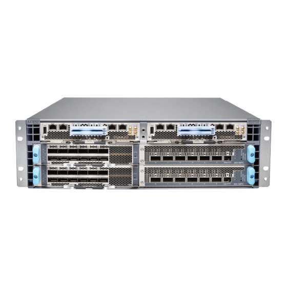
MX10003 3D Universal Edge Router Quick
Start
September 2017
Part Number: 530-080552
Revision 01
Contents
Copyright © 2017, Juniper Networks, Inc.
This document describes how to install the Juniper Networks
Edge Router.
MX10003 Quick Start Description . . . . . . . . . . . . . . . . . . . . . . . . . . . . . . . . . . . . . . . 3
Step 1: Prepare the Site for MX10003 Installation . . . . . . . . . . . . . . . . . . . . . . . . . . 4
Router Rack Requirements . . . . . . . . . . . . . . . . . . . . . . . . . . . . . . . . . . . . . . . . . 4
Router Clearance Requirements . . . . . . . . . . . . . . . . . . . . . . . . . . . . . . . . . . . . . 5
Router Cooling and Airflow Requirements . . . . . . . . . . . . . . . . . . . . . . . . . . . . . 5
Tools Required to Prepare the MX10003 Router for Installation . . . . . . . . . . . 6
Step 2: Install the MX10003 Chassis in the Rack . . . . . . . . . . . . . . . . . . . . . . . . . . . 6
Step 3: Connect the Grounding Cable . . . . . . . . . . . . . . . . . . . . . . . . . . . . . . . . . . . . 9
Step 4: Connect External Devices and Cables . . . . . . . . . . . . . . . . . . . . . . . . . . . . . 10
Connecting the Router to a Network for Out-of-Band Management . . . . . . . . 11
Connecting the Router to a Console Device . . . . . . . . . . . . . . . . . . . . . . . . . . . 12
Connecting the Router to External Clocking and Timing Devices . . . . . . . . . . 13
Connecting 1-PPS and 10-MHz Timing Devices to the Router . . . . . . . . . 13
Connecting a Time-of-Day Device to the Router . . . . . . . . . . . . . . . . . . . 14
Connecting a BITS External Clocking Device to the Router . . . . . . . . . . . 14
Step 5: Connect Power Cables . . . . . . . . . . . . . . . . . . . . . . . . . . . . . . . . . . . . . . . . . 15
Connect Power to an AC Router . . . . . . . . . . . . . . . . . . . . . . . . . . . . . . . . . . . . 15
Connect Power to a DC Router . . . . . . . . . . . . . . . . . . . . . . . . . . . . . . . . . . . . . 17
Step 6: Install the Air Filter Unit . . . . . . . . . . . . . . . . . . . . . . . . . . . . . . . . . . . . . . . . 19
Step 7: Perform Initial Software Configuration . . . . . . . . . . . . . . . . . . . . . . . . . . . . 20
Enter Configuration Mode . . . . . . . . . . . . . . . . . . . . . . . . . . . . . . . . . . . . . . . . 20
Configure User Accounts and Passwords . . . . . . . . . . . . . . . . . . . . . . . . . . . . 20
Configure System Attributes . . . . . . . . . . . . . . . . . . . . . . . . . . . . . . . . . . . . . . . 21
Commit the Configuration . . . . . . . . . . . . . . . . . . . . . . . . . . . . . . . . . . . . . . . . 22
Safety Warnings . . . . . . . . . . . . . . . . . . . . . . . . . . . . . . . . . . . . . . . . . . . . . . . . . . . . 22
®
MX10003 3D Universal
1
Advertisement
Table of Contents

Related Manuals for Juniper MX10003


Summary of Contents for Juniper MX10003
-
Page 1: Table Of Contents
Tools Required to Prepare the MX10003 Router for Installation ... 6 Step 2: Install the MX10003 Chassis in the Rack ......6 Step 3: Connect the Grounding Cable . - Page 2 MX10003 3D Universal Edge Router Quick Start Compliance Statements for NEBS ........24 Compliance Statements for EMC Requirements .
-
Page 3: Mx10003 Quick Start Description
The MX10003 line card has six built in QSFP+ optics ports and one slot for a MIC. For a list of MPCs and MICs supported on the MX10003 router, see MX Series Interface Module Reference. -
Page 4: Step 1: Prepare The Site For Mx10003 Installation
Router Clearance Requirements on page 5 Router Cooling and Airflow Requirements on page 5 Tools Required to Prepare the MX10003 Router for Installation on page 6 Router Rack Requirements You can install the router in a four-post rack or cabinet or an open-frame rack. -
Page 5: Router Clearance Requirements
See Figure 2 on page If you are mounting an MX10003 in a rack with other equipment, ensure that the exhaust from the other equipment does not blow into the intake vents of the MX10003 chassis. Figure 2: Clearance Requirements for Airflow and Hardware Maintenance... -
Page 6: Tools Required To Prepare The Mx10003 Router For Installation
MX10003 3D Universal Edge Router Quick Start Figure 3: Airflow Through the MX10003 Router Tools Required to Prepare the MX10003 Router for Installation Blank panels to cover any slots not occupied by a component Mounting brackets, supplied with the router... - Page 7 Step 2: Install the MX10003 Chassis in the Rack Figure 4: Removing the Rear-Mounting Brackets Install the cable management brackets on each side of the front of the chassis, and secure each bracket with screws at the bottom and top of the bracket (see...
- Page 8 MX10003 3D Universal Edge Router Quick Start Install mounting screws into each of the open front-mounting holes aligned with the rack, starting from the bottom, and secure them tightly. On the rear of the chassis, slide the rear-mounting brackets on either side of the chassis until the rear-mounting brackets contact the rack rails.
-
Page 9: Step 3: Connect The Grounding Cable
14–10 AWG (2–5.3 mm²) stranded wire, 60° C wire, or as permitted by local code. To ground the MX10003 router: Verify that a licensed electrician has attached the cable lug provided with the router to the grounding cable. -
Page 10: Step 4: Connect External Devices And Cables
Figure 8: Grounding the MX10003 Router Step 4: Connect External Devices and Cables Figure 9 on page 11 shows the front panel of the MX10003 RCB. All the connections to the router are made through the RCBs. The external devices are connected through the RCBs. -
Page 11: Connecting The Router To A Network For Out-Of-Band Management
Plug one end of the Ethernet cable (Figure 10 on page 11 shows the connector) into MGMT port on the RCB interface. Plug the other end of the cable into the network device. Figure 10: Out-of-Band Management Cable Connector Copyright © 2017, Juniper Networks, Inc. -
Page 12: Connecting The Router To A Console Device
MX10003 3D Universal Edge Router Quick Start Table 1: Out-of-Band Management Port on the RCB Callout (See Figure 9) Label Description Dedicated management channel for MGMT device maintenance. It is also used by system administrators to monitor and manage the router remotely. -
Page 13: Connecting The Router To External Clocking And Timing Devices
Connecting the Router to External Clocking and Timing Devices Figure 12: Connecting the MX10003 Router to a Management Console Through a Console Server To Console port Console server Figure 13: Connecting the MX10003 Router Directly to a Management Console Table 2: Console Port on the RCB... -
Page 14: Connecting A Time-Of-Day Device To The Router
MX10003 3D Universal Edge Router Quick Start NOTE: Ensure that the 10-MHz or 1-PPS source network equipment contains Low Voltage Complementary Metal Oxide Semiconductor (LVCMOS) or is compatible with low-voltage (3.3 V) transistor-transistor logic (LVTTL). Table 3: Clocking Port on the RCB... -
Page 15: Step 5: Connect Power Cables
The power supplies are hot-insertable and are field-replaceable units (FRUs). You can install up to six power supplies in an MX10003 router. The power supplies install in the rear of the chassis in the slots provided. - Page 16 MX10003 3D Universal Edge Router Quick Start Locate power cords that have a plug appropriate for your geographical location. For more information, see the MX10003 3D Universal Edge Router Hardware Guide at http://www.juniper.net/techpubs/ Attach an ESD grounding strap to your bare wrist and connect the strap to one of the ESD points on the chassis.
-
Page 17: Connect Power To A Dc Router
Connect Power to a DC Router Figure 14: Connecting an AC Power Cord to an MX10003 AC Power Supply Connect Power to a DC Router Table 7: MX10003 DC Power System Input Voltage Item Specification DC input voltage Operating range: –40 through –72 VDC Switch off the dedicated customer-site circuit breakers. - Page 18 MX10003 3D Universal Edge Router Quick Start screw is properly threaded into the terminal. Applying installation torque to the screw when improperly threaded might result in damage to the terminal. CAUTION: The maximum torque rating of the terminal screws on the DC power supply is 6 lb-in.
-
Page 19: Step 6: Install The Air Filter Unit
Step 6: Install the Air Filter Unit Figure 15: Connecting a DC Power Cable to an MX10003 DC Power Supply Step 6: Install the Air Filter Unit The air filter unit is installed on the cable management brackets. Before installing the air filter unit, ensure that the cable management brackets are already installed on the front of the router. -
Page 20: Step 7: Perform Initial Software Configuration
MX10003 3D Universal Edge Router Quick Start Tighten the captive screws to secure the air filter unit. Route the interface cables appropriately. Verify that the cables does not block the access to router components. Step 7: Perform Initial Software Configuration This procedure connects the router to the network but does not enable it to forward traffic. -
Page 21: Configure System Attributes
For more information about static routes, see the Junos OS Administration Library. [edit] root@# set routing-options static route remote-subnet next-hop destination-IP retain no-readvertise Configure the Telnet service at the hierarchy level. [edit system services] [edit] root@# set system services telnet Copyright © 2017, Juniper Networks, Inc. -
Page 22: Commit The Configuration
WARNING: See installation instructions before connecting the router. This is a summary of safety warnings. For a complete list of warnings for this router, including translations, see the MX10003 3D Universal Edge Router Hardware Guide at http://www.juniper.net/techpubs/ Copyright © 2017, Juniper Networks, Inc. - Page 23 Use an external surge protective device (SPD) at the AC input of the router. Only trained and qualified personnel should install or replace the router. Perform only the procedures described in this quick start or the MX10003 3D Universal Edge Router Hardware Guide at . Other services should http://www.juniper.net/techpubs/...
-
Page 24: Compliance Statements For Nebs
The battery return connection is to be treated as an isolated DC return (i.e. DC-I), as defined in GR-1089-CORE. For Juniper Networks systems with AC power supplies, an external surge protective device (SPD) must be used at the AC power source. -
Page 25: Compliance Statements For Emc Requirements
A digital device, pursuant to Part 15 of the FCC Rules. These limits are designed to provide reasonable protection against harmful interference when the equipment is operated in a commercial environment. This equipment generates, uses, and can radiate radio Copyright © 2017, Juniper Networks, Inc. -
Page 26: Junos Os Documentation And Release Notes
7 days a week, 365 days a year. Self-Help Online Tools and Resources For quick and easy problem resolution, Juniper Networks has designed an online self-service portal called the Customer Support Center (CSC) that provides you with the following features: Find CSC offerings: http://www.juniper.net/customers/support/... -
Page 27: Opening A Case With Jtac
Copyright © 2017 Juniper Networks, Inc. All rights reserved. Juniper Networks, the Juniper Networks logo, Juniper, and Junos are registered trademarks of Juniper Networks, Inc. and/or its affiliates in the United States and other countries. All other trademarks may be property of their respective owners.
Need help?
Do you have a question about the MX10003 and is the answer not in the manual?
Questions and answers