
Related Manuals for Juniper MX5


Summary of Contents for Juniper MX5
- Page 1 MX5, MX10, MX40, and MX80 Universal Routing Platforms Hardware Guide Modified: 2019-04-01 Copyright © 2019, Juniper Networks, Inc.
- Page 2 END USER LICENSE AGREEMENT The Juniper Networks product that is the subject of this technical documentation consists of (or is intended for use with) Juniper Networks software. Use of such software is subject to the terms and conditions of the End User License Agreement (“EULA”) posted at https://support.juniper.net/support/eula/.
-
Page 3: Table Of Contents
MX5, MX10, MX40, and MX80 Chassis ........ - Page 4 DC Power Cable Specifications ....... . . 42 MX5, MX10, MX40, and MX80 Host Subsystem ......42 MX5, MX10, MX40, and MX80 Routing Engine Description .
- Page 5 Initial Installation and Configuration ....... . . 75 MX5, MX10, MX40, and MX80 Installation Summary ..... . . 75 Unpacking and Mounting the MX5, MX10, MX40, and MX80 .
- Page 6 Maintaining the MX5, MX10, MX40, and MX80 Routing Engine ... 97 Maintaining the MX5, MX10, MX40, and MX80 Air Filter ....98 Maintaining the MX5, MX10, MX40, and MX80 Air Filter .
- Page 7 Troubleshooting Hardware ........127 Troubleshooting the MX5, MX10, MX40, and MX80 ..... . . 127 Troubleshooting Resources for MX5, MX10, MX40, and MX80 Routers .
- Page 8 MX80 Routers ..........176 Statements of Volatility for Juniper Network Devices ..... . 176 viii Copyright ©...
- Page 9 Figure 5: Front View of the MX5 Router ....... . .
- Page 10 Safety and Compliance Information ....... . . 141 Figure 64: ESD Points on the MX5, MX10, MX40, and MX80 Chassis ..147 Figure 65: Placing a Component into an Electrostatic Bag .
- Page 11 Table 3: MX5 Router Models ........
- Page 12 Table 32: MX80 Site Preparation Checklist ......59 Table 33: MX5, MX10, MX40, and MX80 Physical Specifications ....61 Table 34: Router Environmental Specifications .
-
Page 13: About The Documentation
® To obtain the most current version of all Juniper Networks technical documentation, see the product documentation page on the Juniper Networks website at https://www.juniper.net/documentation/ If the information in the latest release notes differs from the information in the documentation, follow the product Release Notes. -
Page 14: Merging A Full Example
MX5, MX10, MX40, and MX80 Universal Routing Platforms Hardware Guide Merging a Full Example To merge a full example, follow these steps: From the HTML or PDF version of the manual, copy a configuration example into a text file, save the file with a name, and copy the file to a directory on your routing platform. -
Page 15: Documentation Conventions
Alerts you to the risk of personal injury from a laser. Indicates helpful information. Best practice Alerts you to a recommended use or implementation. Table 2 on page xvi defines the text and syntax conventions used in this guide. Copyright © 2019, Juniper Networks, Inc. -
Page 16: Table 2: Text And Syntax Conventions
MX5, MX10, MX40, and MX80 Universal Routing Platforms Hardware Guide Table 2: Text and Syntax Conventions Convention Description Examples Bold text like this Represents text that you type. To enter configuration mode, type the configure command: user@host> configure Fixed-width text like this Represents output that appears on the user@host>... -
Page 17: Documentation Feedback
Requesting Technical Support Technical product support is available through the Juniper Networks Technical Assistance Center (JTAC). If you are a customer with an active Juniper Care or Partner Support Services support contract, or are covered under warranty, and need post-sales technical support, you can access our tools and resources online or open a case with JTAC. -
Page 18: Self-Help Online Tools And Resources
MX5, MX10, MX40, and MX80 Universal Routing Platforms Hardware Guide Self-Help Online Tools and Resources For quick and easy problem resolution, Juniper Networks has designed an online self-service portal called the Customer Support Center (CSC) that provides you with the... -
Page 19: Overview
MX5, MX10, MX40, and MX80 Router Overview on page 19 MX5, MX10, MX40, and MX80 Router Models on page 22 MX5, MX10, MX40, and MX80 Hardware Components and CLI Terminology on page 23 MX5, MX10, MX40, and MX80 Router Overview... -
Page 20: Mx5, Mx10, Mx40, And Mx80 Hardware Overview
MX5, MX10, MX40, and MX80 Universal Routing Platforms Hardware Guide Multichassis link aggregation group (MC-LAG) implementation supports stateful chassis, card, and port redundancy. Application-Aware Networking—On MX Series routers you can use deep packet inspection to detect applications, and by using the user-defined policies, you can determine traffic treatment for each application. -
Page 21: Figure 1: Mx5 Router
Chapter 1: Overview MX5 router: Allows usage of the MIC slot labeled , which comes prepopulated 1/MIC 0 with the Gigabit Ethernet MIC with SFP. Figure 1: MX5 Router 20-port Gigabit Ethernet MIC CONS OLE PS 1 ETHE RNET M X5 -T... -
Page 22: Mx5, Mx10, Mx40, And Mx80 Router Models
A fixed version of the MX80 router (model number: MX80-48T) has 48 fixed 10/100/1000Base-T RJ45 ports in place of the MIC slots. For a list of MICs supported on the MX5, MX10, MX40, and modular MX80 routers, see “MICs Supported by MX Series Routers” on page 46... -
Page 23: Terminology
MX5, MX10, MX40, and MX80 Hardware Components and CLI Terminology The MX5, MX10, MX40, and MX80 routers support the components in Table 7 on page listed in alphabetic order. Table 7: MX5, MX10, MX40, and MX80 Routers Hardware Components and CLI Terminology Component Hardware Model Number CLI Name... -
Page 24: Mx5, Mx10, Mx40, And Mx80 Chassis
MX5, MX10, MX40, and MX80 Universal Routing Platforms Hardware Guide Table 7: MX5, MX10, MX40, and MX80 Routers Hardware Components and CLI Terminology (continued) Component Hardware Model Number CLI Name Description Cooling system, including fan trays and air filters MX5, MX10, MX40, and MX80... -
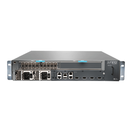
Page 25: Figure 5: Front View Of The Mx5 Router
Chapter 1: Overview Figure 5: Front View of the MX5 Router MIC slots point CONS OLE PS 1 ETHE RNET EXT CLK M X5 -T SYS OK ONLIN E LINK OFFLI NE LINK LINK LINK 0/ MIC 0 AC power supplies... -
Page 26: Mx5, Mx10, Mx40, And Mx80 Baseboard Description
Fan tray (and air filter) Figure 9: Front View of the MX80 Router (Modular Chassis) MIC slots point AC power supplies Front panel Figure 10: Rear View of the MX5, MX10, MX40, and MX80 Routers Protective earthing terminal point slot Clock... -
Page 27: Baseboard Components
Packet Forwarding Engine processor, which includes a 1-GHz CPU, a system controller, and 1 GB of SDRAM. Connects to the Routing Engine through a Gigabit Ethernet link. Clock logic. MX5, MX10, MX40, and MX80 Cable Management Bracket Description The cable management bracket (see Figure 11 on page 28) consists of plastic dividers and installs on the left side of the chassis. -
Page 28: Mx5, Mx10, Mx40, And Mx80 Front Panel Description
Connecting MX5, MX10, MX40, and MX80 Routers to Management Devices on page 91 Connecting Interface Cables to MX5, MX10, MX40, and MX80 Routers Maintaining Cables That Connect to MX5, MX10, MX40, and MX80 MICs on page 113 MX5, MX10, MX40, and MX80 Front Panel Description The front panel is located on the front of the router and allows you to view status and troubleshooting information at a glance. -
Page 29: Front Panel Components
Chapter 1: Overview Figure 13: Front Panel on the Modular MX5, MX10, MX40, and MX80 Routers Alarm Routing Console Ethernet LEDs Engine port port System status ONLINE/ OFFLINE ONLINE/ Reset Auxiliary Clock OFFLINE port port ports 10-Gigabit Ethernet MIC button... -
Page 30: Alarm Leds On The Mx5, Mx10, Mx40, And Mx80 Front Panel
MX5, MX10, MX40, and MX80 Universal Routing Platforms Hardware Guide Figure 14: USB Memory Device in an MX5, MX10, MX40, and MX80 Router USB Memory card Alarm LEDs on the MX5, MX10, MX40, and MX80 Front Panel Two alarm LEDs are located at the left of the front panel. The circular red LED lights to indicate a critical condition that can result in a system shutdown. -
Page 31: Routing Engine Led On The Front Panel
Routing Engine is transitioning online. See Also Troubleshooting Resources for MX5, MX10, MX40, and MX80 Routers on page 127 Troubleshooting the MX5, MX10, MX40, and MX80 Fan Tray on page 129 Troubleshooting the MX5, MX10, MX40, and MX80 MICs on page 130... -
Page 32: Mx5, Mx10, Mx40, And Mx80 Power System Description
DC Power Cable Specifications for MX5, MX10, MX40, and MX80 Routers on page 41 MX5, MX10, MX40, and MX80 Power System Description The MX5, MX10, MX40, and MX80 routers use either AC or DC power supplies (see Figure 15 on page 33 Figure 16 on page 33). -
Page 33: Ac Power Supply Description
Chapter 1: Overview Figure 15: AC Power Supplies Installed in an MX5, MX10, MX40, and MX80 Router AC power supplies Figure 16: DC Power Supplies Installed in an MX5, MX10, MX40, and MX80 Router DC power supplies AC Power Supply Description on page 33... -
Page 34: Dc Power Supply Description
MX5, MX10, MX40, and MX80 Universal Routing Platforms Hardware Guide Figure 17: AC Power Supply Ejector lever Status LED Handle AC power Power inlet switch WARNING: The router is pluggable type A equipment installed in a restricted-access location. It has a separate protective earthing terminal (sized for SAE 10-32 ground screws) provided on the chassis in addition to the grounding pin of the power supply cord. -
Page 35: Mx5, Mx10, Mx40, And Mx80 Routers Ac Power Specifications
6 A @ 110 VAC or 3 A @ 220 VAC maximum See Also AC Power Electrical Safety Guidelines and Warnings for MX5, MX10, MX40, and MX80 Routers on page 167 Power Consumption for an AC-Powered MX5, MX10, MX40, and MX80 Router... -
Page 36: Table 15: Ac Base Router Power Requirements For The Fixed Mx5, Mx10, Mx40, And Mx80 Routers
36, and Table 17 on page 36 to calculate the power consumption and thermal output for your hardware configuration. Table 15: AC Base Router Power Requirements for the Fixed MX5, MX10, MX40, and MX80 Routers Fixed Chassis Power Requirement (Watts) -
Page 37: Mx80 Router
See Also Maintaining the MX5, MX10, MX40, and MX80 Power Supplies on page 114 Replacing an MX5, MX10, MX40, and MX80 AC Power Supply on page 115 AC Power Circuit Breaker Requirements for the MX5, MX10, MX40, and MX80 Router... - Page 38 MX5, MX10, MX40, and MX80 Universal Routing Platforms Hardware Guide Table 18: AC Power Cord Specifications (continued) Country Model Number Electrical Specification Plug Type China CBL-JX-PWR-CH 250 VAC, 10 A, 50 Hz GB2099.1 1996 and GB1002 1996 (CH1-10P) Europe (except Italy and...
-
Page 39: Mx5, Mx10, Mx40, And Mx80 Routers Dc Power Specifications
DC input current rating 13 A @ –48 VDC Power Consumption for a DC-Powered MX5, MX10, MX40, and MX80 Router To allow for future growth so that you can operate the router in any hardware configuration without upgrading the power infrastructure, we recommend that you provision at least 13 A @ –48 VDC for each input. -
Page 40: Table 21: Dc-Powered Base Router Power Requirements For The Fixed Mx80
Chassis running at high activity, with four 10-Gigabit 320 W 6.7 A Ethernet XFPs, and fans running at high speed (approximate) Table 22: DC-Powered Base Router Power Requirements for the MX5, MX10, MX40, and Modular MX80 Router Current Power Requirement... -
Page 41: Mx80 Routers
Watts DC * 3.41 = BTU/hr 500 * 3.41 = 1,705 BTU/hr DC Power Circuit Breaker Requirements for the MX5, MX10, MX40, and MX80 Routers Each DC power supply has a single DC input (–48 VDC and return) that requires a dedicated circuit breaker. -
Page 42: Dc Power Cable Lug Specifications
MX5, MX10, MX40, and MX80 Routing Engine LED on page 43 MX5, MX10, MX40, and MX80 Routing Engine Description The Routing Engine is built-in on the MX5, MX10, MX40, and MX80 baseboard and cannot be replaced. The Routing Engine consists of the following components: Processor—Runs Junos OS to maintain the router's routing tables and routing protocols. -
Page 43: Mx5, Mx10, Mx40, And Mx80 Routing Engine Led
On the fixed MX80 chassis, the MICs come preinstalled and cannot be replaced. On the modular MX5, MX10, MX40, and MX80 chassis, you can install a variety of MICs in the two front slots of the router, and the optional Multiservices MIC can be installed in the rear slot. -
Page 44: Fixed (Built-In) Mics
“MICs Supported by MX Series Routers” on page Fixed (Built-in) MICs Built-in 10-Gigabit Ethernet MIC The built-in 10-Gigabit Ethernet MIC is fixed on the MX5, MX10, MX40, and MX80 routers. The MIC is labeled 0/MIC 0 and is located on the front panel. The built-in 10-Gigabit... - Page 45 Modular Interface Card LEDs” on page See Also Maintaining the MX5, MX10, MX40, and MX80 MICs on page 103 Troubleshooting the MX5, MX10, MX40, and MX80 MICs on page 130 Replacing an MX5, MX10, MX40, and MX80 MIC on page 104...
-
Page 46: Mics Supported By Mx Series Routers
Junos OS release for MICs on MX2010 and MX2020 routers. Table 26 on page 50 list the first supported Junos OS release for MICs on MX5, MX10, and MX40 routers. Table 27 on page 52 lists the first supported Junos OS release for MICs on MX80 and MX104 routers. - Page 47 15.1F7 (Multi-Rate) MICs with SFP SONET/SDH OC3/STM1 MIC-3D-8OC3OC12-4OC48 11.2 15.1F7 (Multi-Rate) MICs with SFP Channelized SONET/SDH MIC-3D-4CHOC3-2CHOC12 11.4 15.1F7 OC3/STM1 (Multi-Rate) MICs with SFP Channelized SONET/SDH MIC-3D-8CHOC3-4CHOC12 11.4 15.1F7 OC3/STM1 (Multi-Rate) MICs with SFP Copyright © 2019, Juniper Networks, Inc.
-
Page 48: Table 25: Mics Supported By Mx2010 And Mx2020 Routers
MX5, MX10, MX40, and MX80 Universal Routing Platforms Hardware Guide Table 24: MICs Supported by MX240, MX480, MX960 and MX2008 Routers (continued) MX240, MX480, and MX960 MIC Name MIC Model Number Ports Routers MX2008 Routers Channelized OC3/STM1 MIC-3D-4COC3-1COC12-CE 12.2 15.1F7... - Page 49 CFP2-ACO 15.1F6 15.1F6 17.1R1 17.1R1 Multi-Rate SONET/SDH OC3/STM1 MIC-3D-4OC3OC12-1OC48 12.3 12.3 (Multi-Rate) MICs with SFP SONET/SDH OC3/STM1 MIC-3D-8OC3OC12-4OC48 12.3 12.3 (Multi-Rate) MICs with SFP Channelized SONET/SDH MIC-3D-4CHOC3-2CHOC12 12.3 12.3 OC3/STM1 (Multi-Rate) MICs with SFP Copyright © 2019, Juniper Networks, Inc.
-
Page 50: Table 26: Mics Supported By Mx5, Mx10, And Mx40 Routers
MX5, MX10, MX40, and MX80 Universal Routing Platforms Hardware Guide Table 25: MICs Supported by MX2010 and MX2020 Routers (continued) MIC Name MIC Model Number Ports MX2010 Routers MX2020 Routers Channelized SONET/SDH MIC-3D-8CHOC3-4CHOC12 12.3 12.3 OC3/STM1 (Multi-Rate) MICs with SFP... - Page 51 Chapter 1: Overview Table 26: MICs Supported by MX5, MX10, and MX40 Routers (continued) MIC Name MIC Model Number Ports MX10 MX40 Gigabit Ethernet MIC with SFP MIC-3D-20GE-SFP-E 13.2R2 13.2R2 13.2R2 Gigabit Ethernet MIC with SFP MIC-3D-20GE-SFP-EH – – –...
-
Page 52: Table 27: Mics Supported By Mx80 And Mx104 Routers
MX5, MX10, MX40, and MX80 Universal Routing Platforms Hardware Guide Table 27: MICs Supported by MX80 and MX104 Routers MIC Name MIC Model Number Ports MX80 MX104 ATM MIC with SFP MIC-3D-8OC3-2OC12-ATM 12.1 13.3 DS3/E3 DS3/E3 MIC MIC-3D-8DS3-E3, 11.4 13.3... -
Page 53: Table 28: Mics Supported By Mx10003 Router
MIC Model Number Ports MX10003 Multi-Rate Multi-Rate Ethernet MIC (12-Port JNP-MIC1 17.3 Multi-Rate MIC with QSFP+) Multi-Rate Ethernet MIC (12-Port JNP-MIC1-MACSEC 17.3R2 Multi-Rate MACsec MIC with QSFP+) See Also MX Series MIC Overview MIC/MPC Compatibility Copyright © 2019, Juniper Networks, Inc. -
Page 54: Mx5, Mx10, Mx40, And Mx80 Port And Interface Numbering
For a complete list of media types, see Interface Naming Overview in the MX Series Interface Module Reference guide. fpc—Slot in which the MPC is installed. On the MX5, MX10, MX40, and MX80 routers, the MPCs are built into the chassis and are represented in the CLI as either... -
Page 55: Figure 21: Mx5, Mx10, Mx40, And Mx80 Interface Port Mapping
MX Series Interface Module Reference Table 29 on page 55 summarizes the relationship between the components and the interface names. Table 29: MX5, MX10, MX40, and MX80 Components and Their Interface Names Component Name in the CLI Interface Names Built-in 4-port 10-Gigabit Ethernet MIC... -
Page 56: Port And Interface Numbering On Mx80-48T Routers
MX5, MX10, MX40, and MX80 Universal Routing Platforms Hardware Guide Table 29: MX5, MX10, MX40, and MX80 Components and Their Interface Names (continued) Component Name in the CLI Interface Names Multiservices MIC installed in the rear of the MS-MIC-16G ge/0/2/0... -
Page 57: Mx5, Mx10, Mx40, And Mx80 Modular Interface Card Leds
See Also MX5, MX10, MX40, and MX80 Hardware Components and CLI Terminology on page 23 MX5, MX10, MX40, and MX80 Modular Interface Card LEDs The fixed 10-Gigabit Ethernet Modular Interface Card (MIC) has link LEDs located on the front panel. - Page 58 MX5, MX10, MX40, and MX80 Universal Routing Platforms Hardware Guide Copyright © 2019, Juniper Networks, Inc.
-
Page 59: Chapter 2 Site Planning, Preparation, And Specifications
MX5, MX10, MX40, and MX80 Site Preparation Checklist on page 59 MX5, MX10, MX40, and MX80 Site Guidelines and Requirements on page 61 MX5, MX10, MX40, and MX80 Network Cable and Transceiver Planning on page 67 MX5, MX10, MX40, and MX80 Management, and Console Port Specifications and... - Page 60 MX5, MX10, MX40, and MX80 Installation Summary on page 75 Documentation Tools Required to Install MX5, MX10, MX40, and MX80 Chassis in the Rack on page 80 Installing MX5, MX10, MX40, and MX80 Chassis in the Rack on page 81...
-
Page 61: Mx5, Mx10, Mx40, And Mx80 Site Guidelines And Requirements
Chapter 2: Site Planning, Preparation, and Specifications MX5, MX10, MX40, and MX80 Site Guidelines and Requirements MX5, MX10, MX40, and MX80 Routers Physical Specifications on page 61 MX5, MX10, MX40, and MX80 Router Environmental Specifications on page 62 MX5, MX10, MX40, and MX80 Router Grounding Specifications on page 62... -
Page 62: Mx5, Mx10, Mx40, And Mx80 Router Environmental Specifications
110-18 of the National Electrical Code, ANSI/NFPA 70. See Also Routine Maintenance Procedures for MX5, MX10, MX40, and MX80 Routers on page 97 General Safety Guidelines for Juniper Networks Devices on page 143 General Safety Warnings for Juniper Networks Devices on page 144... -
Page 63: Grounding Cable Lug Specifications
(13.3 mm ), minimum 60° C wire, or as required by the local code. See Also Tools and Parts Required for MX5, MX10, MX40, and MX80 Router Grounding and Power Connections on page 83 Copyright © 2019, Juniper Networks, Inc. -
Page 64: Mx5, Mx10, Mx40, And Mx80 Rack Requirements
MX5, MX10, MX40, and MX80 Universal Routing Platforms Hardware Guide Preventing Electrostatic Discharge Damage to an MX5, MX10, MX40, and MX80 Router on page 146 MX5, MX10, MX40, and MX80 Routers AC Power Specifications on page 35 MX5, MX10, MX40, and MX80 Routers DC Power Specifications on page 39 MX5, MX10, MX40, and MX80 Rack Requirements The router can be installed in a rack. -
Page 65: Mx5, Mx10, Mx40, And Mx80 Routers Clearance Requirements For Airflow And Hardware Maintenance
Chapter 2: Site Planning, Preparation, and Specifications Table 35: MX5, MX10, MX40, and MX80 Rack Requirements and Specifications (continued) Rack Requirement Guidelines Rack connection to the building Secure the rack to the building structure. structure If earthquakes are a possibility in your geographic area, secure the rack to the floor. -
Page 66: Mx5, Mx10, Mx40, And Mx80 Routers Cabinet Requirements And Specifications
Table 36 on page 66 summarizes cabinet requirements and specifications for MX5, MX10, MX40, and MX80 routers. Table 36: Cabinet Requirements and Specifications for an MX5, MX10, MX40, and MX80 Router Cabinet Requirement Guidelines for the MX80 Router Cabinet size and clearance The minimum-sized cabinet that can accommodate the router is 19-in. -
Page 67: Mx5, Mx10, Mx40, And Mx80 Network Cable And Transceiver Planning
Chapter 2: Site Planning, Preparation, and Specifications Table 36: Cabinet Requirements and Specifications for an MX5, MX10, MX40, and MX80 Router (continued) Cabinet Requirement Guidelines for the MX80 Router Cabinet airflow requirements When you install the router in a cabinet, you must ensure that ventilation through the cabinet is sufficient to prevent overheating. -
Page 68: Series Routers
(JTAC) can help you diagnose the source of the problem. Your JTAC engineer might recommend that you check the third-party optic or cable and potentially replace it with an equivalent Juniper Networks optic or cable that is qualified for the device. -
Page 69: Attenuation And Dispersion In Fiber-Optic Cable
You can use the Hardware Compatibility Tool to find information about the pluggable transceivers supported on your Juniper Networks device. To calculate the power budget and power margin, perform the following tasks: Calculating Power Budget for Fiber-Optic Cable on page 70 Calculating Power Margin for Fiber-Optic Cable on page 70 Copyright ©... -
Page 70: Calculating Power Budget For Fiber-Optic Cable
MX5, MX10, MX40, and MX80 Universal Routing Platforms Hardware Guide Calculating Power Budget for Fiber-Optic Cable To ensure that fiber-optic connections have sufficient power for correct operation, you need to calculate the link's power budget, which is the maximum amount of power it can transmit. -
Page 71: Routing Engine Interface Cable Specifications For Mx5, Mx10, Mx40, And Mx80 Routers
Routing Engine Interface Cable Specifications for MX5, MX10, MX40, and MX80 Routers Table 38 on page 71 lists the specifications for the cables that connect to management ports. -
Page 72: And Pinouts
RJ-45 Connector Pinouts for the ETHERNET Port on MX5, MX10, MX40, and MX80 Routers on page 73 RJ-45 Connector Pinouts for the AUX and CONSOLE Ports on MX5, MX10, MX40, and MX80 Routers The ports on the front panel labeled... -
Page 73: Rj-45 Connector Pinouts For The Ethernet Port On Mx5, Mx10, Mx40, And Mx80 Routers
MX5, MX10, MX40, and MX80 Routing Engine Description on page 42 Maintaining the MX5, MX10, MX40, and MX80 Routing Engine on page 97 RJ-45 Connector Pinouts for the ETHERNET Port on MX5, MX10, MX40, and MX80 Routers The port on the front panel labeled... - Page 74 MX5, MX10, MX40, and MX80 Universal Routing Platforms Hardware Guide Copyright © 2019, Juniper Networks, Inc.
-
Page 75: Chapter 3 Initial Installation And Configuration
MX5, MX10, MX40, and MX80 Installation Summary on page 75 Unpacking and Mounting the MX5, MX10, MX40, and MX80 on page 76 Connecting the MX5, MX10, MX40, and MX80 Routers to Power on page 82 Connecting MX5, MX10, MX40, and MX80 Routers to Management Devices on page 91... -
Page 76: Unpacking And Mounting The Mx5, Mx10, Mx40, And Mx80
Moving the Mounting Brackets for Center-Mounting MX5, MX10, MX40, and MX80 Routers on page 79 Tools Required to Install MX5, MX10, MX40, and MX80 Chassis in the Rack on page 80 Installing MX5, MX10, MX40, and MX80 Chassis in the Rack on page 81... -
Page 77: Verifying The Mx5, Mx10, Mx40, And Mx80 Routers Parts Received
Save the shipping carton and packing materials in case you later need to move or ship the router. Verifying the MX5, MX10, MX40, and MX80 Routers Parts Received A packing list is included in each shipment. Check the parts in the shipment against the items on the packing list. -
Page 78: Table 42: Accessory Box Parts List
MX5, MX10, MX40, and MX80 Universal Routing Platforms Hardware Guide Table 41: Parts List for a Fully Configured Router (continued) Component Quantity Documentation Roadmap Blank panels for slots without components installed One blank panel for each slot not occupied by a component... -
Page 79: Installing The Mx5, Mx10, Mx40, And Mx80 Cable Management Bracket
Tighten the screws at the bottom and top of the bracket. Figure 28: Installing the Cable Management Bracket Moving the Mounting Brackets for Center-Mounting MX5, MX10, MX40, and MX80 Routers Two removable mounting brackets are attached to the mounting holes closest to the... -
Page 80: Tools Required To Install Mx5, Mx10, Mx40, And Mx80 Chassis In The Rack
Figure 29: Front-Mounting the Brackets on MX5, MX10, MX40, and MX80 Routers Figure 30: Center-Mounting the Brackets on MX5, MX10, MX40, and MX80 Routers Tools Required to Install MX5, MX10, MX40, and MX80 Chassis in the Rack To install the router, you need the following tools and parts:... -
Page 81: Installing Mx5, Mx10, Mx40, And Mx80 Chassis In The Rack
Chapter 3: Initial Installation and Configuration Installing MX5, MX10, MX40, and MX80 Chassis in the Rack To install the router in the rack (see Figure 31 on page 82 Figure 32 on page 82): CAUTION: If you are installing more than one router in a rack, install the lowest one first. -
Page 82: Connecting The Mx5, Mx10, Mx40, And Mx80 Routers To Power
Power Connections on page 83 Grounding MX5, MX10, MX40, and MX80 Routers on page 83 Connecting Power to an AC-Powered MX5, MX10, MX40, and MX80 Router on page 84 Powering On an AC-Powered MX5, MX10, MX40, and MX80 Router on page 85... -
Page 83: Tools And Parts Required For Mx5, Mx10, Mx40, And Mx80 Router Grounding And Power Connections
Chapter 3: Initial Installation and Configuration Tools and Parts Required for MX5, MX10, MX40, and MX80 Router Grounding and Power Connections To ground and provide power to the router, you need the following tools and parts: Phillips (+) screwdrivers, numbers 1 and 2 2.5-mm flat-blade (–) screwdriver... -
Page 84: Router
Dress the grounding cable, and verify that it does not touch or block access to router components, and that it does not drape where people could trip on it. Figure 33: Grounding Points on MX5, MX10, MX40, and MX80 Routers Protective... -
Page 85: Powering On An Ac-Powered Mx5, Mx10, Mx40, And Mx80 Router
Repeat Step through Step for the remaining power supply. Powering On an AC-Powered MX5, MX10, MX40, and MX80 Router To power on an AC-powered router: Verify that the power supplies are fully inserted in the chassis. Verify that each AC power cord is securely inserted into its appliance inlet. -
Page 86: Router
You must provide the power cables (the cable lugs are supplied with the router). For power cable specifications, “DC Power Cable Specifications for MX5, MX10, MX40, and MX80 Routers” on page Copyright © 2019, Juniper Networks, Inc. - Page 87 Ensure that each screw is properly threaded into the terminal. Applying installation torque to the screw when improperly threaded may result in damage to the terminal. Copyright © 2019, Juniper Networks, Inc.
-
Page 88: Powering On A Dc-Powered Mx5, Mx10, Mx40, And Mx80 Router
Figure 34: Connecting DC Power to the Router See Also MX5, MX10, MX40, and MX80 Router Grounding Specifications on page 62 Powering On a DC-Powered MX5, MX10, MX40, and MX80 Router To power on a DC-powered router: Verify that an external management device is connected to one of the Routing Engine... - Page 89 LED lights blue steadily. If the status LED on the power supply is blinking red, the power supply is not functioning normally. Repeat the installation and cabling procedures. Copyright © 2019, Juniper Networks, Inc.
-
Page 90: Powering Off Mx5, Mx10, Mx40, And Mx80 Routers
MX5, MX10, MX40, and MX80 Universal Routing Platforms Hardware Guide NOTE: After powering off a power supply, wait at least 60 seconds before turning it back on. After powering on a power supply, wait at least 60 seconds before turning it off. -
Page 91: Connecting Mx5, Mx10, Mx40, And Mx80 Routers To Management Devices
See Also request system halt Connecting MX5, MX10, MX40, and MX80 Routers to Management Devices Connecting the Router to a Network for Out-of-Band Management on page 91 Connecting the Router to a Management Console or Auxiliary Device on page 91... -
Page 92: Figure 37: Routing Engine Console And Auxiliary Cable Connector
10-Gigabit Ethernet MIC button Related Installing the MX5, MX10, MX40, and MX80 Cable Management Bracket on page 79 Documentation Connecting Interface Cables to MX5, MX10, MX40, and MX80 Routers Initially Configuring MX5, MX10, MX40, and MX80 Routers on page 93... -
Page 93: Initially Configuring Mx5, Mx10, Mx40, And Mx80 Routers
Chapter 3: Initial Installation and Configuration Initially Configuring MX5, MX10, MX40, and MX80 Routers The MX5, MX10, MX40, and MX80 routers are shipped with the Junos operating system (OS) preinstalled and ready to be configured when the router is powered on. Two 4-GB internal NAND flash devices ( ) are located on the baseboard. - Page 94 MX5, MX10, MX40, and MX80 Universal Routing Platforms Hardware Guide Configure the name of the router. If the name includes spaces, enclose the name in quotation marks (“ ”). [edit] root@# set system host-name host-name Create a management console user account.
- Page 95 (Optional) Display the configuration to verify that it is correct. [edit] root@# show system { host-name host-name; domain-name domain-name; backup-router address; root-authentication { authentication-method (password | public-key); name-server { address; interfaces { fxp0 { unit 0 { family inet { address address/prefix-length; Copyright © 2019, Juniper Networks, Inc.
- Page 96 Related Connecting MX5, MX10, MX40, and MX80 Routers to Management Devices on page 91 Documentation Powering On an AC-Powered MX5, MX10, MX40, and MX80 Router on page 85 Powering On a DC-Powered MX5, MX10, MX40, and MX80 Router on page 88...
-
Page 97: Chapter 4 Maintaining Components
Maintaining the MX5, MX10, MX40, and MX80 Routing Engine Purpose On the MX5, MX10, MX40, and MX80 router, the Routing Engine is fixed inside the chassis. For optimum router performance, verify the condition of the Routing Engine. Copyright © 2019, Juniper Networks, Inc. -
Page 98: Maintaining The Mx5, Mx10, Mx40, And Mx80 Air Filter
0.07 See Also MX5, MX10, MX40, and MX80 Routing Engine Description on page 42 Routing Engine Interface Cable Specifications for MX5, MX10, MX40, and MX80 Routers on page 71 show chassis routing-engine Maintaining the MX5, MX10, MX40, and MX80 Air Filter... -
Page 99: Replacing An Mx5, Mx10, Mx40, And Mx80 Air Filter
MX5, MX10, MX40, and MX80 Cooling System Description Replacing an MX5, MX10, MX40, and MX80 Air Filter Removing an MX5, MX10, MX40, and MX80 Air Filter on page 99 Installing an MX5, MX10, MX40, and MX80 Air Filter on page 100... -
Page 100: Installing An Mx5, Mx10, Mx40, And Mx80 Air Filter
Release latch See Also Preventing Electrostatic Discharge Damage to an MX5, MX10, MX40, and MX80 Router on page 146 Installing an MX5, MX10, MX40, and MX80 Air Filter The air filter installs on the right side of the fan tray. To install the air filter (see... -
Page 101: Maintaining The Mx5, Mx10, Mx40, And Mx80 Fan Tray
Securing the air filter in the fan tray Maintaining the MX5, MX10, MX40, and MX80 Fan Tray Maintaining the MX5, MX10, MX40, and MX80 Fan Tray on page 101 Replacing an MX5, MX10, MX40, and MX80 Fan Tray on page 102... -
Page 102: Replacing An Mx5, Mx10, Mx40, And Mx80 Fan Tray
Replacing an MX5, MX10, MX40, and MX80 Fan Tray Removing an MX5, MX10, MX40, and MX80 Fan Tray on page 102 Installing an MX5, MX10, MX40, and MX80 Fan Tray on page 103 Removing an MX5, MX10, MX40, and MX80 Fan Tray... -
Page 103: Installing An Mx5, Mx10, Mx40, And Mx80 Fan Tray
Maintaining the MX5, MX10, MX40, and MX80 MICs on page 103 Replacing an MX5, MX10, MX40, and MX80 MIC on page 104 Replacing an MX5, MX10, MX40, and MX80 SFP or XFP Transceiver on page 111 Maintaining Cables That Connect to MX5, MX10, MX40, and MX80 MICs on page 113... -
Page 104: Replacing An Mx5, Mx10, Mx40, And Mx80 Mic
MIC interfaces being removed no longer function. In the MX5, MX10, MX40, and modular configuration of the MX80 router, the MICs can be installed in two slots in the front of the router. A MIC weighs less than 2 lb (0.9 kg). - Page 105 If you are not reinstalling a MIC into the emptied MIC slot within a short time, install a blank MIC panel over the slot to maintain proper airflow in the chassis card cage. Copyright © 2019, Juniper Networks, Inc.
-
Page 106: Installing An Mx5, Mx10, Mx40, And Mx80 Mic
MX5, MX10, MX40, and MX80 Universal Routing Platforms Hardware Guide Figure 43: Removing a MIC Figure 44: Removing a Dual-Wide MIC Ejector levers Installing an MX5, MX10, MX40, and MX80 MIC To install a MIC (see Figure 46 on page... -
Page 107: Figure 45: Installing The Septum
Do not leave a fiber-optic transceiver uncovered except when you are inserting or removing cable. The safety cap keeps the port clean and prevents accidental exposure to laser light. Insert the appropriate cables into the cable connectors on the MIC. Copyright © 2019, Juniper Networks, Inc. -
Page 108: Figure 46: Installing A Mic
MX5, MX10, MX40, and MX80 Universal Routing Platforms Hardware Guide Arrange each cable to prevent the cable from dislodging or developing stress points. Secure the cable so that it is not supporting its own weight as it hangs to the floor. -
Page 109: Installing An Mx10, Mx40, Mx80, And Mx104 Dual-Wide Mic
Align the rear of the MIC with the guides located at the corners of the MIC slot. Slide the MIC into the MIC slot until it is firmly seated in the chassis. CAUTION: Slide the MIC straight into the slot to avoid damaging the components on the MIC. Copyright © 2019, Juniper Networks, Inc. - Page 110 MX5, MX10, MX40, and MX80 Universal Routing Platforms Hardware Guide Verify that the ejector levers are engaged by pushing them toward the router. If the MIC uses fiber-optic cable, remove the rubber safety cap from each transceiver and the end of each cable.
-
Page 111: Replacing An Mx5, Mx10, Mx40, And Mx80 Sfp Or Xfp Transceiver
Chapter 4: Maintaining Components Figure 48: Installing a Dual-Wide MIC Replacing an MX5, MX10, MX40, and MX80 SFP or XFP Transceiver Small form-factor pluggable transceivers (SFPs) and 10-gigabit small form-factor pluggables (XFPs) are optical transceivers that are installed in a MIC. SFPs and XFPs are hot-insertable and hot-removable. -
Page 112: Installing An Mx5, Mx10, Mx40, And Mx80 Transceiver
MX5, MX10, MX40, and MX80 Universal Routing Platforms Hardware Guide Use needlenose pliers to pull the ejector handle out from the transceiver. Grasp the transceiver ejector handle, and pull the transceiver approximately 0.5 in. (1.3 cm) out of the MIC. -
Page 113: Maintaining Cables That Connect To Mx5, Mx10, Mx40, And Mx80 Mics
For more information about the component LEDs, see the Series Interface Module Reference Maintaining Cables That Connect to MX5, MX10, MX40, and MX80 MICs Purpose For optimum router performance, verify the condition of the cables that connect to the MICs. -
Page 114: Maintaining The Mx5, Mx10, Mx40, And Mx80 Power Supplies And Cables
Replacing an MX5, MX10, MX40, and MX80 AC Power Supply on page 115 Replacing an MX5, MX10, MX40, and MX80 AC Power Supply Cord on page 117 Replacing an MX5, MX10, MX40, and MX80 DC Power Supply on page 118... -
Page 115: Replacing An Mx5, Mx10, Mx40, And Mx80 Ac Power Supply
Video: Replacing an MX5, MX10, MX40, and MX80 AC Power Supply Removing an MX5, MX10, MX40, and MX80 AC Power Supply on page 115 Installing an MX5, MX10, MX40, and MX80 AC Power Supply on page 116 Removing an MX5, MX10, MX40, and MX80 AC Power Supply... -
Page 116: Installing An Mx5, Mx10, Mx40, And Mx80 Ac Power Supply
MX5, MX10, MX40, and MX80 Universal Routing Platforms Hardware Guide To remove an AC power supply (see Figure 50 on page 116): Switch off the dedicated customer site circuit breaker for the power supply, and remove the power cord from the AC power source. Follow the instructions for your site. -
Page 117: Replacing An Mx5, Mx10, Mx40, And Mx80 Ac Power Supply Cord
Figure 51: Installing an AC Power Supply Replacing an MX5, MX10, MX40, and MX80 AC Power Supply Cord Disconnecting an MX5, MX10, MX40, and MX80 AC Power Supply Cord on page 117 Connecting an MX5, MX10, MX40, and MX80 AC Power Supply Cord on page 118... -
Page 118: Cord
LED lights green steadily. Replacing an MX5, MX10, MX40, and MX80 DC Power Supply Removing an MX5, MX10, MX40, and MX80 DC Power Supply on page 118 Installing an MX5, MX10, MX40, and MX80 DC Power Supply on page 120... - Page 119 Carefully move the power cables out of the way. Press the latch located on the left side of the power supply, to release it from the chassis. Pull the power supply straight out of the chassis. Copyright © 2019, Juniper Networks, Inc.
-
Page 120: Installing An Mx5, Mx10, Mx40, And Mx80 Dc Power Supply
MX5, MX10, MX40, and MX80 Universal Routing Platforms Hardware Guide Figure 52: Removing a DC Power Supply Figure 53: Disconnecting the DC Power Cables Installing an MX5, MX10, MX40, and MX80 DC Power Supply WARNING: Before performing DC power procedures, ensure that power is removed from the DC circuit. - Page 121 On each of the DC power supplies, switch the DC circuit breaker to the center position before moving it to the on ( ) position. Copyright © 2019, Juniper Networks, Inc.
-
Page 122: Replacing An Mx5, Mx10, Mx40, And Mx80 Dc Power Supply Cable
Figure 55: Connecting the DC Power Cables Replacing an MX5, MX10, MX40, and MX80 DC Power Supply Cable Disconnecting an MX5, MX10, MX40, and MX80 DC Power Supply Cable on page 123 Connecting an MX5, MX10, MX40, and MX80 DC Power Supply Cable on page 124... - Page 123 Chapter 4: Maintaining Components Disconnecting an MX5, MX10, MX40, and MX80 DC Power Supply Cable WARNING: Before performing DC power procedures, ensure that power is removed from the DC circuit. To ensure that all power is off, locate the circuit...
-
Page 124: Cable
MX5, MX10, MX40, and MX80 Universal Routing Platforms Hardware Guide Connecting an MX5, MX10, MX40, and MX80 DC Power Supply Cable WARNING: Before performing DC power procedures, ensure that power is removed from the DC circuit. To ensure that all power is off, locate the circuit... -
Page 125: Figure 56: Connecting Power Cables To The Dc Power Supply
MX5, MX10, MX40, and MX80 Power System Description on page 32 Installing an MX5, MX10, MX40, and MX80 DC Power Supply on page 120 Disconnecting an MX5, MX10, MX40, and MX80 DC Power Supply Cable on page 123 Preventing Electrostatic Discharge Damage to an MX5, MX10, MX40, and MX80 Router... - Page 126 MX5, MX10, MX40, and MX80 Universal Routing Platforms Hardware Guide DC Power Cable Specifications for MX5, MX10, MX40, and MX80 Routers on page 41 Copyright © 2019, Juniper Networks, Inc.
-
Page 127: Troubleshooting Hardware
Troubleshooting the MX5, MX10, MX40, and MX80 on page 127 Troubleshooting the MX5, MX10, MX40, and MX80 Troubleshooting Resources for MX5, MX10, MX40, and MX80 Routers on page 127 Troubleshooting the MX5, MX10, MX40, and MX80 Fan Tray on page 129... -
Page 128: Front Panel Leds
MX5, MX10, MX40, and MX80 Universal Routing Platforms Hardware Guide There are two classes of alarm messages: Chassis alarms—Indicate a problem with a chassis component such as the cooling system or power supplies. Interface alarms—Indicate a problem with a specific network interface. -
Page 129: Troubleshooting The Mx5, Mx10, Mx40, And Mx80 Fan Tray
Chapter 5: Troubleshooting Hardware Troubleshooting the MX5, MX10, MX40, and MX80 Fan Tray Problem Description: The fans in the fan tray are not functioning normally. Solution Follow these guidelines to troubleshoot the fans: Check the alarm LEDs on the front panel. -
Page 130: Troubleshooting The Mx5, Mx10, Mx40, And Mx80 Mics
MX Series Interface Module Reference Check the status of a MIC by issuing the CLI command. The show chassis fpc pic-status MIC slots in the MX5, MX10, MX40, and modular MX80 router are labeled 1/MIC 0 . The fixed MIC is labeled 1/MIC 1 0/MIC 0 user@host>... - Page 131 See Also MX5, MX10, MX40, and MX80 Power System Description on page 32 MX5, MX10, MX40, and MX80 Power Supply LED on page 34 show chassis environment pem...
- Page 132 MX5, MX10, MX40, and MX80 Universal Routing Platforms Hardware Guide show chassis alarms Copyright © 2019, Juniper Networks, Inc.
-
Page 133: Components
Packing MX5, MX10, MX40, and MX80 Routers for Shipment on page 139 Returning a Hardware Component to Juniper Networks, Inc. In the event of a hardware failure, please contact Juniper Networks, Inc. to obtain a Return Material Authorization (RMA) number. This number is used to track the returned material at the factory and to return repaired or new components to the customer as needed. -
Page 134: Numbers
To return a defective hardware component: Determine the part number and serial number of the defective component. Obtain an RMA number from the Juniper Networks Technical Assistance Center (JTAC). You can send e-mail or telephone as described above. Provide the following information in your e-mail message or during the telephone call:... -
Page 135: Mx5, Mx10, Mx40, And Mx80 Chassis Serial Number Label
The serial number label is located on the top of the fan tray toward the front (see Figure 59 on page 135). Figure 59: MX5, MX10, MX40, and MX80 Fan Tray Serial Number Label Serial number ID label Copyright © 2019, Juniper Networks, Inc. -
Page 136: Mx5, Mx10, Mx40, And Mx80 Mic Serial Number Label
MX5, MX10, MX40, and MX80 Universal Routing Platforms Hardware Guide MX5, MX10, MX40, and MX80 MIC Serial Number Label The exact location may be slightly different on different MICs, depending on the placement of components on the MIC board (see... -
Page 137: Mx5, Mx10, Mx40, And Mx80 Power Supply Serial Number Label
ID label See Also MX5, MX10, MX40, and MX80 Modular Interface Card Description on page 43 MX5, MX10, MX40, and MX80 Power Supply Serial Number Label The serial number label is located on the top of the power supply (see Figure 63 on page 137). -
Page 138: Contacting Customer Support To Obtain Return Material Authorization
MX5, MX10, MX40, and MX80 Universal Routing Platforms Hardware Guide Contacting Customer Support to Obtain Return Material Authorization If you are returning a device or hardware component to Juniper Networks for repair or replacement, obtain a Return Material Authorization (RMA) number from Juniper Networks Technical Assistance Center (JTAC). -
Page 139: Packing Mx5, Mx10, Mx40, And Mx80 Routers For Shipment
To pack the router for shipment: Retrieve the shipping box and packing materials in which the router was originally shipped. If you do not have these materials, contact your Juniper Networks representative about approved packaging materials. On the console or other management device connected to the Routing Engine, enter CLI operational mode and issue the following command to shut down the router software. - Page 140 MX5, MX10, MX40, and MX80 Universal Routing Platforms Hardware Guide Securely tape the box closed. Write the RMA number on the exterior of the box to ensure proper tracking. See Also Returning a Hardware Component to Juniper Networks, Inc. on page 133 Contacting Customer Support Copyright ©...
-
Page 141: Safety And Compliance Information
General Electrical Safety Guidelines and Electrical Codes for Juniper Networks Devices on page 167 AC Power Electrical Safety Guidelines and Warnings for MX5, MX10, MX40, and MX80 Routers on page 167 DC Power Electrical Safety Warnings for Juniper Networks Devices on page 168... - Page 142 MX5, MX10, MX40, and MX80 Universal Routing Platforms Hardware Guide CAUTION: You must observe the specified guidelines to avoid minor injury or discomfort to you, or severe damage to the hardware device. WARNING: This symbol alerts you to the risk of personal injury from a laser.
-
Page 143: General Safety Guidelines For Juniper Networks Devices
Documentation Installation Safety Warnings for Juniper Networks Devices on page 149 Maintenance and Operational Safety Warnings for Juniper Networks Devices on page 158 General Electrical Safety Warnings for Juniper Networks Devices on page 163 DC Power Electrical Safety Warnings for Juniper Networks Devices on page 168... -
Page 144: General Safety Warnings For Juniper Networks Devices
MX5, MX10, MX40, and MX80 Universal Routing Platforms Hardware Guide Do not open or remove chassis covers or sheet metal parts unless instructions are provided in this documentation. Such an action could cause severe electrical shock. Do not push or force any objects through any opening in the chassis frame. Such an action could result in electrical shock or fire. -
Page 145: Restricted-Access Area Warning
è controllata dall'autorità responsabile della zona. Advarsel Denne enheten er laget for installasjon i områder med begrenset adgang. Et område med begrenset adgang gir kun adgang til servicepersonale som bruker et spesielt verktøy, lås og nøkkel, eller en annen Copyright © 2019, Juniper Networks, Inc. -
Page 146: Preventing Electrostatic Discharge Damage To An Mx5, Mx10, Mx40, And Mx80
General Electrical Safety Warnings for Juniper Networks Devices on page 163 DC Power Electrical Safety Warnings for Juniper Networks Devices on page 168 Preventing Electrostatic Discharge Damage to an MX5, MX10, MX40, and MX80 Router Many router hardware components are sensitive to damage from static electricity. Some components can be impaired by voltages as low as 30 V. -
Page 147: Fire Safety Requirements For Juniper Networks Devices
(see Figure 65 on page 147). If you are returning a component, place it in an electrostatic bag before packing it. Figure 64: ESD Points on the MX5, MX10, MX40, and MX80 Chassis point (rear panel) point... -
Page 148: Fire Suppression
To keep warranties effective, do not use a dry chemical fire extinguisher to control a fire at or near a Juniper Networks device. If a dry chemical fire extinguisher is used, the unit is no longer eligible for coverage under a service agreement. -
Page 149: Mx5, Mx10, Mx40 And Mx80 Chassis Lifting Guidelines
Chapter 7: Safety and Compliance Information MX5, MX10, MX40 and MX80 Chassis Lifting Guidelines The weight of a fully configured chassis is about 30 lb (13.6 kg). Observe the following guidelines for lifting and moving the router: Before moving the router, read the guidelines in “MX5, MX10, MX40, and MX80 Site... -
Page 150: Installation Instructions Warning
MX5, MX10, MX40, and MX80 Universal Routing Platforms Hardware Guide Installation Instructions Warning WARNING: Read the installation instructions before you connect the hardware equipment to a power source. Waarschuwing Raadpleeg de installatie-aanwijzingen voordat u het systeem met de voeding verbindt. - Page 151 à assurer la protection du personnel: Le rack sur lequel est monté le router doit être fixé à la structure du bâtiment. Si cette unité constitue la seule unité montée en casier, elle doit être placée dans le bas. Copyright © 2019, Juniper Networks, Inc.
- Page 152 MX5, MX10, MX40, and MX80 Universal Routing Platforms Hardware Guide Si cette unité est montée dans un casier partiellement rempli, charger le casier de bas en haut en plaçant l'élément le plus lourd dans le bas. Si le casier est équipé de dispositifs stabilisateurs, installer les stabilisateurs avant de monter ou de réparer l'unité...
- Page 153 Router måste installeras i en ställning som är förankrad i byggnadens struktur. Om denna enhet är den enda enheten på ställningen skall den installeras längst ned på ställningen. Copyright © 2019, Juniper Networks, Inc.
-
Page 154: Ramp Warning
Documentation General Safety Warnings for Juniper Networks Devices on page 144 Maintenance and Operational Safety Warnings for Juniper Networks Devices on page 158 General Laser Safety Guidelines for Juniper Networks Devices Devices with single-mode optical interfaces are equipped with laser transmitters, which are considered Class 1 Laser product by the U.S. -
Page 155: Laser Safety Warnings For Juniper Networks Devices
Related Laser Safety Warnings for Juniper Networks Devices on page 155 Documentation General Safety Warnings for Juniper Networks Devices on page 144 Laser Safety Warnings for Juniper Networks Devices... -
Page 156: Laser Beam Warning
MX5, MX10, MX40, and MX80 Universal Routing Platforms Hardware Guide Varoitus Luokan 1 valodiodituote. Attention Alarme de produit LED Class I. Warnung Class 1 LED-Produktwarnung. Avvertenza Avvertenza prodotto LED di Classe 1. Advarsel LED-produkt i klasse 1. Aviso Produto de classe 1 com LED. -
Page 157: Radiation From Open Port Apertures Warning
öppningar. Related General Safety Guidelines for Juniper Networks Devices on page 143 Documentation General Safety Warnings for Juniper Networks Devices on page 144 Installation Safety Warnings for Juniper Networks Devices on page 149 Copyright ©... -
Page 158: Maintenance And Operational Safety Warnings For Juniper Networks Devices
MX5, MX10, MX40, and MX80 Universal Routing Platforms Hardware Guide Maintenance and Operational Safety Warnings for Juniper Networks Devices As you maintain the hardware equipment, observe the following warnings: Battery Handling Warning on page 158 Jewelry Removal Warning on page 159... -
Page 159: Jewelry Removal Warning
Advarsel Fjern alle smykker (inkludert ringer, halskjeder og klokker) før du skal arbeide på utstyr som er koblet til kraftledninger. Metallgjenstander som Copyright © 2019, Juniper Networks, Inc. -
Page 160: Lightning Activity Warning
MX5, MX10, MX40, and MX80 Universal Routing Platforms Hardware Guide er koblet til kraftledninger og jord blir svært varme og kan forårsake alvorlige brannskader eller smelte fast til polene. Aviso Antes de trabalhar em equipamento que esteja ligado a linhas de corrente, retire todas as jóias que estiver a usar (incluindo anéis, fios e... -
Page 161: Operating Temperature Warning
área que exceda a temperatura máxima recomendada de 40° C. Para evitar a restrição à circulação de ar, deixe pelo menos um espaço de 15,2 cm à volta das aberturas de ventilação. Copyright © 2019, Juniper Networks, Inc. -
Page 162: Product Disposal Warning
MX5, MX10, MX40, and MX80 Universal Routing Platforms Hardware Guide ¡Atención! Para impedir que un encaminador de la serie router se recaliente, no lo haga funcionar en un área en la que se supere la temperatura ambiente máxima recomendada de 40° C. Para impedir la restricción de la entrada de aire, deje un espacio mínimo de 15,2 cm alrededor de las aperturas para... -
Page 163: In Case Of An Electrical Accident
If possible, send another person to get medical aid. Otherwise, assess the condition of the victim, then call for help. Related General Safety Guidelines for Juniper Networks Devices on page 143 Documentation General Safety Warnings for Juniper Networks Devices on page 144... -
Page 164: Grounding Requirements And Warning
MX5, MX10, MX40, and MX80 Universal Routing Platforms Hardware Guide Advarsel Dette utstyret skal jordes. Forviss deg om vertsterminalen er jordet ved normalt bruk. Aviso Este equipamento deverá estar ligado à terra. Certifique-se que o host se encontra ligado à terra durante a sua utilização normal. -
Page 165: Midplane Energy Hazard Warning
Varning! Denna enhet har mer än en strömförsörjningsanslutning; alla anslutningar måste vara helt avlägsnade innan strömtillförseln till enheten är fullständigt bruten. Copyright © 2019, Juniper Networks, Inc. -
Page 166: Power Disconnection Warning
Varning! Innan du arbetar med ett chassi eller nära strömförsörjningsenheter skall du för växelströmsenheter dra ur nätsladden och för likströmsenheter bryta strömmen vid överspänningsskyddet. Related DC Power Electrical Safety Warnings for Juniper Networks Devices on page 168 Documentation Copyright © 2019, Juniper Networks, Inc. -
Page 167: Devices
Related In Case of an Electrical Accident on page 163 Documentation AC Power Electrical Safety Guidelines and Warnings for MX5, MX10, MX40, and MX80 Routers The following electrical safety guidelines apply to an AC-powered router: You can order three-wire electrical cords with a grounding-type plug that fits only a grounding-type power outlet. -
Page 168: Dc Power Electrical Safety Warnings For Juniper Networks Devices
The power cable warning in Japanese is as follows: Related Replacing an MX5, MX10, MX40, and MX80 AC Power Supply Cord on page 117 Documentation MX5, MX10, MX40, and MX80 Routers AC Power Specifications on page 35... -
Page 169: Dc Power Disconnection Warning
Para se assegurar que toda a corrente foi DESLIGADA, localize o disjuntor no painel que serve o circuito de corrente contínua e coloque-o na posição OFF Copyright © 2019, Juniper Networks, Inc. -
Page 170: Dc Power Wiring Terminations Warning
MX5, MX10, MX40, and MX80 Universal Routing Platforms Hardware Guide (Desligado), segurando nessa posição a manivela do interruptor do disjuntor com fita isoladora. ¡Atención! Antes de proceder con los siguientes pasos, comprobar que la alimentación del circuito de corriente continua (CC) esté cortada (OFF). Para asegurarse de que toda la alimentación esté... - Page 171 Storleken på dessa kontakter måste vara avpassad till ledningarna och måste kunna hålla både isoleringen och ledaren fastklämda. Related General Safety Warnings for Juniper Networks Devices on page 144 Documentation General Electrical Safety Warnings for Juniper Networks Devices on page 163 Copyright © 2019, Juniper Networks, Inc.
-
Page 172: Mx5, Mx10, Mx40, And Mx80 Dc Power Electrical Safety Guidelines
MX5, MX10, MX40, and MX80 Universal Routing Platforms Hardware Guide MX5, MX10, MX40, and MX80 DC Power Electrical Safety Guidelines The following electrical safety guidelines apply to a DC-powered router: A DC-powered router is equipped with a DC terminal block that is rated for the power requirements of a maximally configured router. -
Page 173: Site Electrical Wiring Guidelines For Mx Series Routers
Agency Approvals and Compliance Statements Agency Approvals for MX5, MX10, MX40, and MX80 Routers on page 174 Compliance Statements for NEBS for MX5, MX10, MX40, and MX80 Routers on page 175 Compliance Statements for EMC Requirements for MX5, MX10, MX40, and MX80 Routers on page 175 Copyright ©... -
Page 174: Agency Approvals For Mx5, Mx10, Mx40, And Mx80 Routers
Compliance Statements for Acoustic Noise for MX5, MX10, MX40, and MX80 Routers on page 176 Agency Approvals for MX5, MX10, MX40, and MX80 Routers The MX5, MX10, MX40, and MX80 routers comply with the following standards: Safety CAN/CSA-22.2 No. 60950-00/UL 1950 Third Edition, Safety of Information... -
Page 175: Mx80 Routers
You must provision a readily accessible device outside of the equipment to disconnect power. The device must also be rated based on local electrical code practice. Compliance Statements for EMC Requirements for MX5, MX10, MX40, and MX80 Routers Canada on page 175... -
Page 176: Japan
98/101/EEC. The product documentation includes instructional information about the proper method of reclamation and recycling. Compliance Statements for Acoustic Noise for MX5, MX10, MX40, and MX80 Routers The router complies with NEBS Level 3 requirements: GR-63-CORE: NEBS, Physical Protection... - Page 177 XRE200 External Routing Engine LN Series: LN1000–CC MX Series: M7i Compact Forwarding Engine Board (CFEB) M40e and M10i M320 MX5, MX10, MX40, and MX80 MX240, MX480, and MX960 RE-A-2000 Route Engine RE-S-X6-64G Routing Engine Copyright © 2019, Juniper Networks, Inc.
- Page 178 MX5, MX10, MX40, and MX80 Universal Routing Platforms Hardware Guide QFX Series: QFX3008-I QFX3100 QFX3500 QFX3600 QFX5100-24Q QFX5100-48S QFX5100-48T QFX5110-32Q QFX5110-48S QFX5200 QFX5200-32C QFX10008 and QFX10016 SRX Series: SRX100 SRX110 SRX210B SRX210H-POE SRX210H-P-MGW SRX220 SRX240H SRX240H-POE SRX300 SRX320 SRX340 and SRX345...
- Page 179 Chapter 7: Safety and Compliance Information SRX-MP-1SERIAL SSG-520M T Series: RE-A-2000 Route Engine Copyright © 2019, Juniper Networks, Inc.
- Page 180 MX5, MX10, MX40, and MX80 Universal Routing Platforms Hardware Guide Copyright © 2019, Juniper Networks, Inc.
Need help?
Do you have a question about the MX5 and is the answer not in the manual?
Questions and answers