
Related Manuals for Konica Minolta CA-100Plus


Summary of Contents for Konica Minolta CA-100Plus
- Page 1 ® Advanced Test Equipment Rentals www.atecorp.com 800-404-ATEC (2832) CRT Color Analyzer CA-100Plus INSTRUCTION MANUAL...
- Page 2 • The contents of this manual are subject to change without prior notice. • Every effort has been made in the preparation of this manual to ensure the accuracy of its contents. However, should you have any questions or find any errors, please contact a Konica Minolta authorized service facility.
-
Page 3: Safety Precautions
AC power cord from the the AC power cord’s plug may cause a fire. If there AC outlet, and contact the nearest Konica Minolta is any dirt or water on the prongs of the AC power authorized service facility. -
Page 4: Foreword
If any irregularity or abnormality is found, turn OFF the power immediately, disconnect the AC power cord, and refer to “Troubleshooting Guide” on page 111. Should the instrument break down, do not try to disassemble by yourself. Contact a Konica Minolta authorized service facility. -
Page 5: Cleaning
● If the optics of the probe gets dirty, wipe it with a soft dry cloth or lens cleaning paper. ● If it not possible to remove dirt from the instrument, contact a Konica Minolta authorized service facility. About This Manual This manual is designed for those who possess basic knowledge of displays. -
Page 6: Table Of Contents
Contents Safety Precautions ..................................1 Foreword ....................................... 2 Notes on Use ....................................2 Notes on Storage ................................... 2 Cleaning ......................................3 About This Manual ..................................3 Manual Structure ......................................6 Names and Functions of Parts ..................................10 About Accessories ......................................13 Standard Accessories .................................. - Page 7 Analyzer Mode ......................................57 1. About Analyzer Mode ................................57 2. Inputting the RGB Emission Characteristic for Analyzer Mode .................... 58 Setting/Changing the Target Color ................................61 1. Setting/Changing the Target Color by Measurement ......................62 2. Setting/changing the target color by entering values ......................64 Other Settings ......................................
-
Page 8: Manual Structure
Explains how to select the measuring probe whose measured value is to be displayed. * Go to the Measurement section if you are going to perform measurement using To the Setting section P. 45-74 Konica Minolta’s calibration standard and are not going to use analog display. - Page 9 Gives detailed explanations on memory channels common to each setting and target colors. When performing measurement using When performing measurement using When performing measure- Konica Minolta’s calibration standard user calibration ment in analyzer mode Setting/Changing the Target Color *1 User Calibration...
- Page 10 This section explains measuring methods. From the Settings section Measurement Page 76 Explains measuring methods, how to hold the measured values and how to read them. White Balance Adjustment in Analyzer Mode Page 80 Explains how to adjust white balance. This section explains communication with PC via RS-232C or USB.
- Page 11 This section explains the following items. Measuring Principle Page 100 Maintenance Page 105 Dimension Diagram Page 106 Error Messages Page 107 Please read when an error message appears in the LCD display section. Troubleshooting Guide Page 111 Please read when the instrument does not function correctly. Specifications Page 114 Measurement/Quick Guide...
-
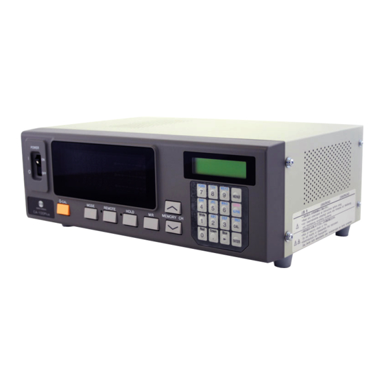
Page 12: Names And Functions Of Parts
Names and Functions of Parts Main Body <Front> 4 Measurement mode indications 1 POWER switch 3 Analog display 5 LCD display 2 Digital display 6 HOLD LED 7 REMOTE LED 9 Tilt stand 8 Key panel <Rear> 11 USB connector 12 RS-232C connector 10 Probe connector [P1] 13 Vertical synchronizing signal input terminal... - Page 13 Main Body <Front> 1 POWER switch ........• Used to turn ON and OFF the power to the instrument. (Page 29) 2 Digital display section ......• Displays the measured values. 3 Analog display section ......• Displays the difference (%) between the measured value and the target color or the difference (%) between measured values.
- Page 14 Measuring Probe CA-P02(2m) /CA-P05(5m) High luminance Measuring Probe CA-PH02(2m) /CA-PH05(5m) Connecting cord (CA-P02/PH02: 2 m/6.6 ft) (CA-P05/PH05: 5 m/6.6 ft) 2 Screw hole ISO screw 5 mm (depth: 6 mm) 1 Receptor area 3 Plug Measuring is done with a probe in intimate contact with the surface of display in the measuring part of this equip- ment.
-
Page 15: About Accessories
About Accessories Standard Accessories ● AC power cord (For 100-120V or 200-240 V) Connect this cord to the AC power connector to supply power to the instrument. For a description of how to connect, refer to page 28. (For 100-120 V) (For 200-240 V) ●... - Page 16 ● 4-Probe Expansion Board CA-B04 Connector Connect measuring probes (CA-P02/CA-P05,CA-PH02/CA-PH05) to this board, to allow simultaneous measurement of the colors at up to 5 points on the display’s surface.It is possible to install Measuring Probes of all types to be coresident. Location of the explanation [P2] [P3]...
-
Page 17: About Ca-100 Compatible Mode
About CA-100 Compatible Mode This instrument offers two modes: “CA-100 compatible mode”, that provides data compatibility with measured data taken by the CRT color analyzer CA-100 and allows communications via RS-232C, and “CA-200” mode, that allows use of the CA-SDK software supplied with this instrument. “CA-100 compatible mode” has been set prior to shipment from the factory. -
Page 18: Function Of Each Key
Function of Each Key Key Panel 1 0-CAL key ..........• Performs zero calibration. Before pressing this key, make sure that the measuring probe is blocked from light. (Page 34) 2 Mode key ..........• Select measurement mode. (Page 40) Measurement mode changes in the following order. - Page 19 REMOTE key ........• Sets the instrument in remote mode (i.e. communication with the PC is possible via RS-232C or USB). (The REMOTE LED will light up. See page 86.) • Pressing this key while the REMOTE key is lit will cancel remote mode.
- Page 20 Cursor key ( ) ........• Used to switch from one option to another in the PROBE, SYNC, Measurement Speed, Number of Digits, and RS232C baud rate screens, which are opened from the menu selection screen. ENTER key ( ) ........• Used to confirm each setting/selection you have made. White, Red, Green, ........
-
Page 21: About Display
About Display 1 Measurement mode 4 LCD display section: indications CH00 EXT [MINOLTA 2 Digital display section 3 Analog display section * This shows when the entire display area is lit. (The LCD display section is not shown.) Measurement mode ......... Displays the measurement mode in which the measured values are displayed. - Page 22 Analog display section ......Displays the difference (%) between the measured value and the tar- get color or the difference (%) between measured values. The range for each dot can be set between 0.1 and 99%. (Page 68) Green The range has been set to 10% prior to factory ship- ment.
- Page 23 ● When Lv (luminance) is below 0.05 cd/m Digital display : blinking (white calibration equivalent to Analog display : blinking Konica Minolta's calibration standard) : Measurement mode : blinking ● When T∆uvLv measurement mode Digital display : “– – –”...
-
Page 25: Installation/Connection
Installation/Connection This section explains how to install the instrument, connect AC power, turn ON/OFF the power, and input the vertical syn- chronizing signal. About Installation Provides operating environmental conditions for the instrument and notes Page 25 on installation. About Connection Explains how to connect measuring probes and connect the power cord. - Page 26 Doing so may result in a fire. For periodic inspection, contact a Konica Minolta When disconnecting the AC power cord’s plug, al- authorized service facility. ways hold the plug and pull it to remove it. Never...
-
Page 27: About Installation
About Installation The operating environmental requirements are given in the “Specifications” of this manual. The instrument must be installed in a place that completely meets these requirements. (Page 114-115) <Notes on Installation> ● Using the instrument in direct sunshine in midsummer or near a heater will cause a rapid rise in its temperature resulting in breakdown. -
Page 28: About Connection
About Connection 1. Connecting a Measuring Probe Before setting the POWER switch to ON, a measuring probe must be connected to the probe connector [P1] on the instrument. [Connecting Method] Probe connector [P1] Set the POWER switch to OFF (“O” position). Insert the probe’s plug into the probe connector [P1], with the probe serial no. -
Page 29: Installing The 4-Probe Expansion Board Ca-B04
2. Installing the 4-Probe Expansion Board CA-B04 When the optional 4-Probe Expansion Board CA-B04 is used Installing the optional 4-Probe Expansion Board CA-B04 in the instrument allows simultaneous measurement of the colors at up to 5 points on the display’s surface. Install the expansion board as shown below. [Installation Method] Remove the cover of the 4-Probe Expansion Board slot. -
Page 30: Connecting The Power
3. Connecting the Power Power voltage range for the instrument — 100 to 240V [Connection Method] Main body Set the POWER switch to OFF (“O” posi- tion). Connect the AC power cord’s connector to the AC power connector on the instrument. AC power connector The AC power cord must be connected as shown in the figure. -
Page 31: Turning The Power On ( | )/Off (●)
Turning the Power ON ( | )/OFF (●) 1. Turning the Power ON ( | )/OFF (●) Before setting the POWER switch to ON ( | ), prepare the following. Connect a measuring probe to the probe connector [P1]. (Page 26) •... -
Page 32: Instrument Status At Power-On
3 digits 10 RS232C baud rate Page 85 9600bps 11 Calibration data (stored) in CH00 to CH99 Page 50 6500K (D65) Konica Minolta’s standard data 12 CA-200 mode/CA-100 compatible mode Page 15 CA-100 compatible mode 13 Luminance unit Page 32 cd/m <Changing the Instrument Status at Power-ON>... - Page 33 Changing Method for parameters 4 to 10 For parameters 4 to 10, switch the LCD display section to the menu selec- tion screen as explained below. Press the key. Menu selection screen The LCD display section will switch to the menu selection screen. MENU : SELECT Press the key until the desired screen is displayed.
-
Page 34: About The Change Of Luminance Unit
3. About the change of Luminance Unit This instrument allows you to switch the unit for the displayed luminance between “cd/m ” or “fL”. The method is given below. 1. Set the POWER switch to ON while holding down the MODE key. “... -
Page 35: Measurement Preparation
Explains how to select the measuring probe whose measured value is to be displayed. To the Setting section * Go to the Measurement section if you are going to perform measurement using Konica Minolta’s calibra- tion standard and are not going to use analog display. -
Page 36: Zero Calibration
Zero Calibration Zero calibration performs zero point adjustment while blocking entry of light into the measuring probe’s receptor. Zero calibration must be performed whenever the POWER switch is set to ON. 1. Performing Zero Calibration <Notes on Zero Calibration> ● If the luminance of the display to be measured is 0.5 cd/m or less (if High luminance Measuring Probe(CA- PH02/05), 1.0 cd/m or less), perform zero calibration after elapse of 30 minutes or more after the POWER... -
Page 37: Zero Calibration Check Method
<Error Messages in LCD Display Section> … For other error messages, refer to page 107. ● “TOO BRIGHT” (During zero calibration) The message ZERO CALIBRATION • Cause : Light is entering the measuring probe’s recep- switches automatically. tor. TOO BRIGHT •... -
Page 38: Selecting, Measurement Speed, Sync Mode, Display Mode
Selecting, Measurement Speed, SYNC Mode, Display Mode and the Number of Display Digits 1. Selecting the Measurement Speed Select the measurement speed according to your application. If the measurement speed is changed, display frequency of the measurement results will change accordingly. The measurement results are displayed at the following frequency. - Page 39 [Operating Procedure] PQRS WXYZ MENU LOCK ALPHA White - SPACE Green Blue ENTER Menu selection screen Press the key. MENU : SELECT The LCD display section will switch to the menu selection PUSH SPACE KEY screen. Measurement speed selection screen Press the key to open the measurement speed SELECT : M-SPD...
-
Page 40: Selecting Sync Mode
2. Selecting SYNC Mode In SYNC mode, measurement time (sampling time) is selected according to the display’s vertical scanning frequency. The following five SYNC modes are available. Select the SYNC mode suitable for the display to be measured. Display’s vertical Measurement time Vertical scanning SYNC Mode... - Page 41 Press the key to confirm the selection. * To use EXT mode, the vertical synchronizing signal used for the display must be input to the instrument. (Page 28) * By default (factory setting), the instrument is set so that EXT mode will be selected automatically when the POWER switch is set to ON. If you want to change this setting, refer to page 30.
-
Page 42: Selecting The Measurement Mode
<Error Messages in LCD Display Section> … For other error messages, refer to page 107. ● “NO SYNC. SIGNAL” (when EXT mode is selected) • Cause 1 : The vertical synchronizing signal used for the display is not connected to the terminal on the instrument. - Page 43 [Selecting Method] Press the MODE key to display the measurement mode you want to select. Measurment MODE key Each time the MODE key is pressed, measurement mode will switch as shown below. xyLv mode Analyzer mode (R Standard) XYZ mode ˘x ˘R ˘x...
-
Page 44: Selecting The Number Of Display Digits
4. Selecting the Number of Display Digits The number of display digits can be selected from 4 or 3. However, T(correlated color temperature) is always displayed in three digits, and flicker is always displayed up to the first decimal place. [Selecting Method] PQRS WXYZ... -
Page 45: Selecting Probe No
When the optional 4-Probe Expansion Board CA-B04 is used Selecting Probe No. Measurement will be performed simultaneously with all the connected measuring probes. However, the digital and analog display sections show only the measurement results taken by the one selected probe. Follow the procedure given below to select the probe connector No. -
Page 47: Settings Section
Page 48 Gives detailed explanations on memory channels common to each setting and target colors. When performing measurement When performing measurement When performing measurement in using Konica Minolta’s calibration using user calibration analyzer mode standard Setting/Changing the Target User Calibration... -
Page 48: Outline Of The Settings Section
Available measurement methods and the settings that must be made are explained below. <Measurement by Konica Minolta’s Calibration Standard> With this method, measurement is performed using Konica Minolta’s calibration standard without calibration. Even if you are setting the target color to the memory channel CH00, measurement must be performed as ex- plained below. -
Page 49: Measurement Mode
<Measurement by Analyzer Mode> With this method, the measured colors are expressed in emission luminance of each R, B and G monochromatic light based on the display’s analyzer mode RGB emission characteristic (which is input to the instrument’s memory channel) and the target color (W). Since the target color is also set, the analog display section can show the deviation of the measured values from the target color. -
Page 50: Before Making Each Setting
(If xylv, T∆uvLv, u'v'Lv or XYZ mea- surement mode is selected, the Konica Minolta’s calibration standard will be used for measurement.) ● In the case of the same memory channels and probes, the RGB emission characteristic for analyzer mode is stored in their common memory irrespective of measurement mode. -
Page 51: About The Target Color
• When you want to set a color that differs from the color used for user calibration as the target color to a user-calibrated memory channel • When you want to perform measurement using Konica Minolta’s calibration standard without user calibration and want to use the analog display function 3 Inputting the RGB emission .... -
Page 52: User Calibration
● When this instrument is used for the first time since shipment from the factory, measurement will be performed based on the calibration carried out by the Konica Minolta’s calibration standard. This applies to all the memory channels. Once user calibration is performed, the following correction will be made when measurement is performed using the obtained correction factor. -
Page 53: Performing White Calibration
2. Performing White Calibration ● User calibration cannot be performed with the memory channel CH00. (CH00 memory channel is provided for measurement that uses the Konica Minolta’s calibration standard.) ● White calibration must be performed for each display type (model). -
Page 54: Measurement Speed
* If measurement is performed with non-user-calibrated memory channel for the first time since shipment from the factory, the Konica Minolta’s calibration standard will be used for the measurement. * To change the target color you set, change it as explained in “1. Setting/Changing the Target Color by Measurement” (page 62). The currently set correction factor for white calibration will remain unchanged even if the target color is changed. -
Page 55: Performing Matrix Calibration
3. Performing Matrix Calibration ● Matrix calibration cannot be performed with the memory channel CH00. (CH00 memory channel is provided for measurement that uses the Konica Minolta’s calibration standard.) ● Matrix calibration must be performed for each display type (model). - Page 56 [Preparation] H01 EXT Ad P1 Press the MODE key to select xyLv measurement mode. Press the MEMORY CH keys until the memory channel where you want to perform user calibration ap- pears. A memory channel other than CH00 must be selected. Place the measuring probe with the display and take mea- surement.
- Page 57 Enter the emission characteristic of B and calibration values (x, y, Lv). 1 Place the measuring probe with the display, which is now emitting monochrome light of B. Currently measured values will be displayed. 2 While the probe is placed with the display, press the HOLD key. U- AL The measured values will be hold and the HOLD LED lights up.
- Page 58 The following alphabet will appear at the “*” position on the LCD display sec- H01 EXT A* P1 tion according to the selected calibration mode. d : Matrix calibration with Konica Minolta’s calibration standard 6500K (D65) “*” position a : White calibration (user calibration) m : Matrix calibration (user calibration) <Error Messages in LCD Display Section>...
-
Page 59: Analyzer Mode
Analyzer Mode 1. About Analyzer Mode <What is Analyzer Mode?> Analyzer measurement mode is provided for adjustment of the display’s white balance. The measured R, B and G beam intensities are expressed individually as percentages of the RGB emission charac- teristics for the display which were previously stored in memory. -
Page 60: Inputting The Rgb Emission Characteristic For Analyzer Mode
2. Inputting the RGB Emission Characteristic for Analyzer Mode The RGB emission characteristic for analyzer mode must be input to each memory channel. When it is input, the target color (W) must also be set. To adjust white balance, the values of the white-balanced white must be entered as the terget color (W). If the RGB emission characteristic for the display’s analyzer mode is input to a memory channel for which the target color has already been set, the previously set target color will be deleted. - Page 61 Press the MODE key to select analyzer measurement Memory channel mode (RGB). H01 EXT Ad P1 Press the MEMORY CH keys until the memory channel where you want to input the RGB emis- sion characteristic appears. Press the key. P1 W R G B The LCD display section will switch to the analyzer mode RGB emis- sion characteristic input screen.
- Page 62 ● If the RGB emission characteristic for analyzer mode is input using a memory channel that has been matrix- calibrated, the correction factor for matrix calibration will be deleted. (Konica Minolta’s calibration standard will be used for measurement if xyLv, T∆uvLv, u'v'Lv or XYZ measurement mode is selected.) ●...
-
Page 63: Setting/Changing The Target Color
The target color must be set in the following cases. • When you want to set the target color for memory channel CH00 • When you want to perform measurement using Konica Minolta’s calibration standard without user calibration and want to use the analog display function •... -
Page 64: Setting/Changing The Target Color By Measurement
1. Setting/Changing the Target Color by Measurement [Operating Procedure] HOLD LED When the optional 4-Probe Expansion Board CA-B04 is used Select the probe no. to which you want to set the target color. The target color can be set independently for each probe connector ([P1] to [P5]) for each memory channel. - Page 65 <Notes when Setting/Changing the Target Color by Measurement> ● Note that the target color is common to all measurement modes (xyLv, T∆uvLv, analyzer, u'v'Lv, XYZ). ● If the luminance of the display to be measured is 0.5 cd/m or less(1.0 cd/m or less when a High Luminance Measuring Probe(CA-PH02/05) is connected.) or if the ambient temperature has changed, zero calibration must be performed before setting the target color.
-
Page 66: Setting/Changing The Target Color By Entering Values
2. Setting/changing the target color by entering values This method can be used for memory channel CH00 only. [Operating Procedure] When the optional 4-Probe Expansion Board CA-B04 is used Select the probe no. to which you want to set the target color. The target color can be set independently for each probe connector ([P1] to [P5]) for each memory channel. - Page 67 Enter target color values (x, y, Lv). For x and y, a value 10000 times the calibration value must be entered. Use the ten-key ( ) to enter the value. The cursor moves to the right each time a value is entered. H00 x y Lv P1 Each time the key is pressed, the cursor moves in the order x→y→Lv→x.
-
Page 68: Other Settings
Other Settings 1. Setting an ID Name An ID name is a name that can be assigned to each memory channel by entering it directly using keys. When measurement is performed, the ID name is displayed together with the memory channel no. and probe no. in the LCD display section. - Page 69 In this example, “EXT D-1.50” is set as the ID name. 1 Press the key. H01 EXT Ad P1 2 Press the key twice. “E” will appear at the cursor position. H01 EXT Ad P1 3 Press the key twice. “X”...
-
Page 70: Setting The Analog Display Range
2. Setting the Analog Display Range The analog display section displays the difference (%) between the measured value and the target color as well as the difference (%) between measured values in the case of a measurement mode. The range for each dot can be set as follows. 1 xyLv, T∆uvLv, u'v'Lv or XYZ measurement mode .. - Page 71 For analyzer mode (G reference) R − G × 100 (%) R/G = B − G × 100 (%) B/G = G − G ∆G = × 100 = G − 100 (%) For analyzer mode (R reference) R − R ∆R = ×...
- Page 72 [Setting Procedure] Menu selection screen Press the MODE key to select the measurement mode MENU : SELECT for which you want to set the range. PUSH SPACE KEY Press the key. Range setting screen The LCD display section will switch to the menu selection screen. (For xyLv, T∆uvLv, u'v'Lv Press the key to open the RANGE setting screen.
- Page 73 <Notes on Range Setting> ● The range settings will be kept even if the POWER switch is set to OFF. The specified analog range will be effective when the POWER switch is set to ON. ● The specified range settings are common to all the probe nos. and memory channels. ●...
-
Page 74: Settings Checking Method
Settings Checking Method 1. Checking the Set Values <Checking the Specified Target Color> H01 x y Lv P1 By pressing the MR key for less than two seconds in xyLv, T∆uvLv, u'v'Lv or XYZ M3189 4079 366.0 mode, the values of the target color for the currently selected memory channel is displayed in the LCD display section as shown on the right. -
Page 75: Checking The Probe Serial No. When Making Settings
2. Checking the Probe Serial No. when Making Settings Period for which the MR key is To check the probe serial no. when making settings, press the MR key for pressed two to four seconds (a bleep will sound after two seconds have elapsed) and check it in the LCD display section. -
Page 77: Measurement Section
Measurement Section This section explains measuring methods. From the Settings Section Measurement Page 76 Explains measuring methods, how to hold the measured values and how to read them. White Balance Adjustment in Analyzer Mode Page 80 Explains how to adjust white balance. -
Page 78: Measurement
This is not necessary if the instrument has already been set up or if you Settings section (page 45) are going to perform measurement using Konica Minolta’s calibration standard and are not going to use the analog display function 1. Performing Measurement... -
Page 79: Holding The Measured Values
● When measurement is implemented, the same Measuring Probe to be used for the User Calibration is necessary. If measurement is carried out by connecting the different Measuring Probe, error message E1 will be displayed. In this case, please replace it with the Measuring Probe that received User Calibration or execute User Calibra <Error Messages in LCD Display Section>... -
Page 80: Displaying The Measured Values
● When Lv (luminance) is below 0.05cd/m Digital display : blinking (white calibration equivalent to Analog display : blinking Konica Minolta's calibration standard) Measurement mode : blinking ● When T∆uvLv measurement mode is selected Digital display section (T and ∆uv) : “_ _ _”... - Page 81 <For Analyzer Mode> If analyzer measurement mode is selected, measurement results will be displayed as shown below. ● Digital display section • Display contents : R, B, G Outputs of the currently measured monochrome ∆G lights R, B and G in ratio (%) to those of the specified target color (W) •...
-
Page 82: White Balance Adjustment In Analyzer Mode
White Balance Adjustment in Analyzer Mode <About Analyzer Mode> White-balance adjustment is most easily done using analyzer mode. In analyzer mode, the measured R, B, and G beam intensities are displayed individually as percentages of the RGB emission characteristics for the display which were previously stored in memory. - Page 83 [Operating Procedure] Block entry of light Place the probe with the display Set the POWER switch to ON. Message displayed DARKEN PROBE when the POWER PUSH 0-CAL KEY Place receptor area of measuring probe switch is set to ON Press the 0-CAL key. face down on a flat surface so that no light ZERO CALIBRATION reaches the receptor area.
- Page 84 Adjust the white balance. Normally, white balance is adjusted by adjusting the cutoff and drive voltages. However, in the procedure below, the display is adjusted so that the white generated on the display matches the target color (W) stored in memory. The method is explained by taking the following cases where the measured values are as follows compared to the target color (W).
-
Page 85: Communications Section
Communications Section This section explains communication with PC via RS-232C or USB. It is designed for those who possess basic knowledge of control- ling the instrument from the PC via RS-232C and know the ba- sic operating methods (Measurement Preparation and Measure- ment sections). -
Page 86: Communicating With Pc
Communicating with PC This instrument allows two-way communication via RS-232C or USB. 1. Communicating with PC via RS-232C Before setting the POWER switch to ON, connect a RS-232C cable (foe 9-pin D-sub Female) to the RS-232C connector on the instrument. Refer to the following for the wiring diagram. [Connecting Method] Set the POWER switch to OFF (O). -
Page 87: Selecting The Rs-232C Baud Rate
2. Selecting the RS-232C Baud Rate The RS-232C baud rate can be changed according to the setting made on the computer that is used for remote measurement. [Operating Procedure] PQRS WXYZ MENU LOCK ALPHA White - SPACE Green Blue ENTER Press the key. -
Page 88: Communicating With Pc Via Usb
3. Communicating with PC via USB The USB cable can be connected/disconnected even if the power to the instrument is ON. However, in this manual, the power must be turned OFF before connecting the USB cable. Communicating with PC via USB is possible in CA-200 mode only. [Connecting Method] USB port Set the POWER switch to OFF. -
Page 89: Communication Method For Ca-100 Compatible (Rs-232C)
Parity check: EVEN Stop bit: 2 bits 2. Inputting Commands (RS-232C) The commands listed starting on page 90 to 93 can be input to the CA-100Plus in ASCII code to control the operation of the CA-100Plus. <About Delimiter> ● Any of three delimiter codes can be used after a command (when inputting single commands) or at the end of a command string (when inputting multiple commands connected by “&”):... - Page 90 ● If the CA-100Plus will not be controlled by the computer, it is recommended that the remote-control mode of the CA-100Plus is not set. If the remote-control mode is set but the computer is not ready to accept data, the time for one measurement becomes longer (by 0.5 seconds for each measuring probe being used) than the time...
- Page 91 3. Operation During Data Communication (RS-232C) <Holding the Measured Values> ● Holding by Inputting a Command • Display hold can be set by inputting the command “H1” from the computer.*1 When display hold is set, the displayed data will not change and data output is only performed once for the data which was mea- sured just before the command was input.*2 •...
-
Page 92: Communication Format
Communication Format for CA-100 Compatible To use the instrument in the same communication environment as CA-100, make sure that “CA-100 compatible mode”, “FAST mode” and “3-digit display mode” are selected. The commands listed in the following tables can be used to control in the CA-100 Compatible. Most of the com- mands listed are applicable to data communication with RS-232C system;... - Page 93 Spaces must not be input before or calibration has been completed. after data. • Range data remains in memory even if CA-100Plus is switched off. Sets memory channel “C memory channel number ” • Corresponds to pressing MEMORY Acceptable range: 00 to 10 (If op- key.
- Page 94 • If the command I, M, A, C, N, or P is input, calibration mode will au- tomatically be canceled. • Corresponds to pressing when CA-100Plus is in analyzer mode. • This command will not be accepted unless “I” has been input and zero calibration has been completed.
- Page 95 Command Function Input format Further information ENTER “E” • Sets present displayed data as tar- get color data in xyLv or T∆uvLv display modes (or in analyzer mode if calibration mode is off). • Stores previously set RBGW val- ues in memory when calibration mode is switched on (if RBGW val- ues have all been set correctly).
-
Page 96: Output Data (Pc ➔ Instrument)
2. OUTPUT DATA (Instrument → → → → →PC ) 1. Measurement Data Measurement data is output by the CA-100Plus according to the present display mode. However, the format of the output data will be slightly different from the format of the displayed data. - Page 97 2. Data Recalled From Memory Target color data in memory can be recalled and output using the command “Kxx”, where xx is the memory channel number from which data is desired. The data which will be recalled and output depends on the present display mode.
- Page 98 3. Status Information Inputting the command “Z” will cause the present settings and status of the CA-100Plus to be output as a 134- character word as shown below. Format: display mode SYNC mode memory channel number and ID name analog display range...
- Page 99 4. Error Messages Error messages which may be output by the CA-100Plus when remote-control mode has been set are listed below. * For information on error messages which may appear in the LCD, see page 107. • In the following, “_” indicates a space.
-
Page 101: Explanation Section
Explanation Section This section explains the following items. Measuring Principle Page 100 Maintenance Page 105 Dimension Diagram Page 106 Error Messages Page 107 Please read when an error message appears in the LCD display section. Troubleshooting Guide Page 111 Please read when the instrument does not function correctly. Specifications Page 114 Measurement/Quick Guide... -
Page 102: Measuring Principle
Measuring Principle 1. Measuring Principle This instrument uses sensors of a spectral sensitivity similar to the CIE 1931 color-matching function ( – – x λ, – yλ, – zλ) to measure RGB emission energy of a color display, and displays the results in xyLv, T, ∆uvLv, u’v’Lv or XYZ values. -
Page 103: About T∆Uvlv
2. About T∆ ∆ ∆ ∆ ∆ uvLv If the instrument’s measurement mode is set to T∆uvLv, the following values can be displayed in the digital display section. • T : Correlated color temperature • ∆uv : Color difference from the blackbody locus •... -
Page 104: Principle Of User Calibration
(R, G and B). Since the matrix correction factor obtained from Konica Minolta’s calibration standard has been set, measured values calculated based on this factor will be acquired when this instrument is used for the first time since shipment... -
Page 105: Principle Of Analyzer Mode
4. Principle of Analyzer Mode In analyzer mode, the emission characteristics of the display’s three monochrome lights (R, G, B) and the target color are set to the instrument’s memory. Once they are set, display’s screen colors obtained by measurement can be converted to beam intensity of each monochromatic light and displayed. - Page 106 The above also applies when only monochrome light G is emitted as well as when only monochrome light B is emitted, and the outputs are shown in Figs. 3 and 4, respectively. Fig. 3 Outputs of Sensors – x λ λ λ λ λ , – yλ λ λ λ λ , and – zλ λ λ λ λ by Emitted Monochrome Light G Fig.
-
Page 107: Maintenance
● If the measuring probe receptor’s objective lens gets dirty, wipe it with a soft dry cloth or lens cleaning paper. ● Should the instrument break down, do not try to disassemble it by yourself. Contact a Konica Minolta autho- rized service facility. -
Page 108: Dimension Diagram
Dimension Diagram <Main Body> <Measuring Probe> ISO 5mm screw(depth : 6mm) -
Page 109: Error Messages
Error Messages The following error messages appear if the instrument does not operate correctly. The table below shows kinds of error message, their meanings (description) and corrective actions. Error Message Cause: (Description) Corrective Action 1 Perform user calibration or set the target color. •... - Page 110 DATA ERR R suring circuit is not functioning correctly. POWER switch is set to ON, the instru- ment has broken down. Contact a Konica Minolta authorized ser- vice facility. • Set the POWER switch to OFF. MEMORY ERROR • The instrument’s memory is abnormal.
- Page 111 (Note) • The key is inoperable if error message *3 is displayed. • The instrument operates as follows if error message *4 is displayed. 1 Clears the display by the MR key. 2 Aborts CAL ON state (i.e. the state that is effective when the key is pressed).
- Page 112 <Relationship Between Probe Serial No. and Error Message “E1”> If “E1” appears, the cause of the error can be located easily by checking the serial no. of the probe used to make settings and the current probe serial no. • Probe serial no. used for making settings : Displayed when the MR key is held down for two to four sec- onds.
-
Page 113: Troubleshooting Guide
If any of the following symptoms occur with the instrument, take the corrective actions given in the table below. If the instrument still does not operate correctly even if the necessary corrective actions are taken, the instrument might have broken down. Contact a Konica Minolta authorized service facility. When doing so, please inform them of the breakdown No. - Page 114 Break- Symptom Action Ref. Check Point down Odd measured Is the receptor of the measuring probe If it is dirty, wipe it with a soft dry cloth or values are dis- clean? lens cleaning paper. played. If the ambient temperature has changed, Is the ambient temperature stable? perform zero calibration.
- Page 115 When the optional 4-Probe Expansion Board CA-B04 is used Break- Symptom Check Point Action Ref. down Probes P2 to P5 Is the 4-Probe Expansion Board installed Install it correctly. c a n n o t b e s e - correctly? lected.
-
Page 116: Specifications
4-Probe Expansion Board CA-B04,Measuring Probe(2 m)CA-P02,Measuring Probe(5 m)CA-P05 *1 : The luminance and chromaticity are measured under Konica Minolta’s conditions (standard CRT(6500 K) is used). *2 : The luminance for monochrome is measured when the reading of luminance for white is 40.00 cd/m *3 : Mesuring probe connected to probe connector P1 only, USB is used(RS-232C;38,400 bps baud rate is used). - Page 117 High lunimance Measuring Probe(5 m)CA-PH05 *1 : The luminance and chromaticity are measured under Konica Minolta’s conditions (standard CRT(6500 K) is used). *2 : The luminance for monochrome is measured when the reading of luminance for white is 40.00 cd/m *3 : Mesuring probe connected to probe connector P1 only, USB is used(RS-232C;38,400 bps baud rate is used).
-
Page 118: Measurement/Quick Guide
Measurement/Quick Guide Before starting measurement, perform necessary preparations as explained in the Installation/Connection section (page 23). <Zero Calibration> Page 34 POWER switch 1. Check that the POWER switch is set to ON. 2. Place receptor area of measuring probe face down on a flat surface so that no light reaches the receptor area. - Page 119 From the front page <Selecting the Number of Display Digits> Page 42 Menu selection screen ENU : SELECT 1. Press the key to display the menu selection screen. PUSH SPACE KEY 2. Press the key to open the number of display digits selec- tion screen.
- Page 120 From the Measurement Preparation section When performing measurement using Konica Minolta calibration stan- dard <Setting/Changing the Target Color> Page 61 2. Setting/Changing the Target Color by Entering Values Page 64 1. Setting/Changing the Target Color by Measurement Page 62 This method can be used for memory channel CH00 only.
- Page 121 From the Measurement Preparation section When performing measurement using user calibration <User Calibration> Page 50 2. Performing Matrix Calibration Page 53 Cannot be performed with memory channel CH00. 1. Performing White Calibration Page 51 Cannot be performed with memory channel CH00. 9,11 6,10 When the optional 4-Probe Expansion Board CA-B04 is used...
- Page 122 From the Measurement Preparation section When performing measurement in analyzer mode <Inputting the RGB Emission Characteristic for <Setting an ID Name> Page 66 Analyzer mode> Page 58 Can be set to all the memory channels. Can be set to all the memory channels. 4,5,6,7 1.
- Page 125 9222-1891-13 AEIDPK(10) Printed in Japan 2002 KONICA MINOLTA SENSING, INC.
Need help?
Do you have a question about the CA-100Plus and is the answer not in the manual?
Questions and answers