
Related Manuals for Konica Minolta CA-310


Summary of Contents for Konica Minolta CA-310
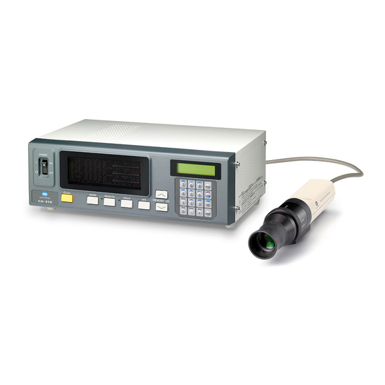
- Page 1 Display Color Analyzer CA-310 INSTRUCTION MANUAL Before using this instrument, please read this manual.
-
Page 2: Safety Symbols
• Every effort has been made in the preparation of this manual to ensure the accuracy of its contents. Konica Minolta-authorized However, should you have any questions or find any errors, please contact a Konica Minolta authorized service facility. • KONICA MINOLTA will not accept any responsibility for consequences arising from the use of the... -
Page 3: Safety Precautions
AC power cord from the power cord, resulting in fire or electric shock. Konica Minolta- AC outlet, and contact the nearest Konica Minolta If the CA-Series will not be used for a long time, authorized service facility. -
Page 4: Foreword
If any irregularity or abnormality is found, turn OFF the power immediately, disconnect the AC power cord, and refer to “Troubleshooting Guide” on page 107. ● Should the instrument break down, do not try to disassemble by yourself. Contact a Konica Minolta - authorized service facility. ●... -
Page 5: Notes On Storage
If the optics of the probe gets dirty, wipe it with a soft dry cloth or lens cleaning paper. ● If it is not possible to remove dirt from the instrument, contact a Konica Minolta - authorized service facility. Notes on transfer ●... -
Page 6: Table Of Contents
Contents Safety Precautions ..................................1 Foreword ....................................... 2 Notes on Use ....................................2 Notes on Storage ................................... 2 Cleaning ......................................3 Notes on transfer ................................... 3 Maintenance ....................................3 Disposal Method ................................... 3 About This Manual ..................................3 Manual Structure ......................................6 Names and Functions of Parts .................................. - Page 7 Before Making Each Setting ..................................48 1. About Memory Channels ................................ 48 2. About the Target Color ................................49 3. Selecting the Calibration Standard (data) ..........................50 User Calibration ......................................51 1. About User Calibration ................................51 2. Performing White Calibration ..............................52 3.
-
Page 8: Manual Structure
Explains how to select the measuring probe whose measured value is to be displayed. * Go to the Measurement section if you are going to perform measurement using To the Setting section P. 45-74 Konica Minolta’s calibration standard and are not going to use analog display. - Page 9 Gives detailed explanations on memory channels common to each setting and target colors. When performing measurement using When performing measurement using When performing measure- Konica Minolta’s calibration standard user calibration ment in analyzer mode Selecting the Calibration Standard Select calibration data.
- Page 10 This section explains measuring methods. From the Settings section Measurement Page 76 Explains measuring methods, how to hold the measured values and how to read them. White Balance Adjustment in Analyzer Mode Page 81 Explains how to adjust white balance. This section explains communication with PC via RS-232C or USB.
- Page 11 This section explains the following items. Measuring Principle Page 90 Maintenance Page 101 Dimension Diagram Page 102 Error Messages Page 103 Please read when an error message appears in the LCD display section. Troubleshooting Guide Page 107 Please read when the instrument does not function correctly. Specifications Page 110 Measurement/Quick Guide...
-
Page 12: Names And Functions Of Parts
Names and Functions of Parts Main Body <Front> 4 Measurement mode indications 1 POWER switch 3 Analog display 5 LCD display 2 Digital display 6 HOLD LED 7 REMOTE LED 9 Tilt stand 8 Key panel <Rear> 11 USB connector 12 RS-232C connector 10 Probe connector [P1] 13 Vertical synchronizing signal input terminal... -
Page 13: Main Body
Main Body <Front> A POWER switch .........• Used to turn ON and OFF the power to the instrument. (Page 29) B Digital display section ......• Displays the measured values. C Analog display section ......• Displays the difference (%) between the measured value and the target color or the difference (%) between measured values. - Page 14 LED Universal Measuring ø27 Probe CA-PU32(2m) /CA-PU35(5m) LED Universal Measuring ø10 Probe CA-PSU32(2m) /CA-PSU35(5m) LED Flicker Measuring ø27 Probe CA-P32(2m) /CA-P35(5m) LED Flicker Measuring ø10 Probe CA-PS32(2m) /CA-PS35(5m) F Standard Hood for CA-210/310 CA-H10/ Small Hood for CA-210/310 CA-HS10 D Screw hole B Pointing ring A Receptor E Plug...
-
Page 15: About Accessories
About Accessories Standard Accessories ● AC power cord (For 100-120V or 200-240 V) Connect this cord to the AC power connector to supply power to the instrument. For a description of how to connect, refer to page 28. (For 100-120 V) ●... -
Page 16: About Measuring Probe
About Measuring Probe Setting a Measuring Probe Two types of screw holes are provided to secure the measuring probe. Tripod screw hole: Used to mount the probe to a tripod. The screw hole depth is 6 mm. ISO screw hole: Used to mount the probe to a jig. An ISO screw (5 mm, depth: 6 mm) can be used. Tripod screw hole ISO screw hole ISO screw hole... -
Page 17: About Pointing Ring
About Pointing Ring When you turn the pointing ring, it stops at two positions (MEAS, 0-CAL). To turn the ring, the stopper must be pulled toward you to unlock it. MEAS : To perform measurement, the ring must be set in this posi- Pointing ring tion. -
Page 18: Function Of Each Key
Function of Each Key Key Panel 1 0-CAL key ..........• Performs zero calibration. Before pressing this key, make sure that the measuring probe is blocked from light. (Page 34) 2 Mode key ..........• Select measurement mode. (Page 38) Measurement mode changes in the following order. - Page 19 You can enter a value for the target color. (Page 65) • When the memory channel other than CH00 is selected as the memory channel You can set CA-310 for input of WRGB data for user calibration. (Page 51) • When an analyzer measurement mode is selected You can set CA-310 for input of RGB emission characteristic and target color (W).
- Page 20 Cursor key ( ) ........• Used to switch from one option to another in the PROBE, SYNC, Measurement Speed, Number of Digits, and RS232C baud rate screens, which are opened from the menu selection screen. ENTER key ( ) ........• Used to confirm each setting/selection you have made. White, Red, Green, ........
-
Page 21: About Display
About Display 1 Measurement mode 4 LCD display section: indications CH00 EXT [MINOLTA 2 Digital display section 3 Analog display section * This shows when the entire display area is lit. (The LCD display section is not shown.) Measurement mode ......... Displays the measurement mode in which the measured values are displayed. - Page 22 Analog display section ......Displays the difference (%) between the measured value and the tar- get color or the difference (%) between measured values. The range for each dot can be set between 0.1 and 99%. (Page 69) ● How to read/when the range is set in “n” % except flicker mode Green For a description of flicker mode refer to page 69.
- Page 23 <Out of Measurement Range> [For xylv, T∆ ∆ ∆ ∆ ∆ uvLv, u'v'Lv or XYZ,Analyzer Mode] ● When the measurement range is exceeded Digital display : “– – – – –” Analog display : Not lit LCD display : “OVER” [For T∆...
-
Page 25: Installation/Connection
Installation/Connection This section explains how to install the instrument, connect AC power and turn the power ON ( | )/OFF( ), and input the vertical synchronizing signal. About Installation Page 25 Provides operating environmental conditions for the instrument and notes on installation. - Page 26 Doing so may result in a fire. For periodic inspection, contact a Konica Minolta- For periodic inspection, contact a Konica Minolta When disconnecting the AC power cord’s plug, al- authorized service facility.
-
Page 27: About Installation
About Installation The operating environmental requirements are given in the “Specifications” of this manual. The instrument must be installed in a place that completely meets these requirements. (Page 110-113) <Notes on Installation> ● Using the instrument in direct sunshine in midsummer or near a heater will cause a rapid rise in its temperature resulting in breakdown. -
Page 28: About Connection
About Connection 1. Connecting a Measuring Probe Before setting the POWER switch to ON ( | ), a measuring probe must be connected to the probe connector [P1] on the instrument. [Connecting Method] Set the POWER switch to OFF (“O” position). Probe connector [P1] Insert the probe’s plug into the probe connector [P1], with the probe serial no. -
Page 29: Installing The 4-Probe Expansion Board Ca-B15
2. Installing the 4-Probe Expansion Board CA-B15 When the optional 4-Probe Expansion Board CA-B15 is used Installing the optional 4-Probe Expansion Board CA-B15 in the instrument allows simultaneous measurement of the colors or flicker** at up to 5 points on the display’s surface. Install the expansion board as shown below. [Installation Method] Remove the cover of the 4-Probe Expansion Board slot. -
Page 30: Connecting The Power
3. Connecting the Power Power voltage range for the instrument — 100 to 240V [Connection Method] Set the POWER switch to OFF (“O” posi- Main body tion). Connect the AC power cord’s connector to the AC power connector on the instrument. AC power connector The AC power cord must be connected as shown in the figure. -
Page 31: Turning The Power On ( | )/Off (O)
Turning the Power ON ( | )/OFF (●) 1. Turning the Power ON ( | )/OFF (●) Before setting the POWER switch to ON ( | ), prepare the following. Connect a measuring probe to the probe connector [P1]. (Page 26) •... -
Page 32: Instrument Status At Power-On
9 Number of display digits Page 42 4 digits 10 Calibration standard Page 50 6500K Konica Minolta’s standard data 11 RS232C baud rate Page 87 38400bps 12 Calibration data (stored) in CH00 to CH99 Page 51 6500K Konica Minolta’s standard data... - Page 33 Changing Method for parameters 4 to 11 For parameters 4 to 11, switch the LCD display section to the menu selec- tion screen as explained below. Press the key. The LCD display section will switch to the menu selection screen. Menu selection screen MENU : SELECT Press the...
-
Page 34: About The Change Of Luminance Unit
3. About the change of Luminance Unit This instrument allows you to switch the unit for the displayed luminance between “cd/m ” or “fL”. The method is given below. 1. Set the POWER switch to ON while holding down the MODE key. “... -
Page 35: Measurement Preparation
Explains how to select the measuring probe whose measured value is to be displayed. To the Setting section * Go to the Measurement section if you are going to perform measurement using Konica Minolta’s calibration standard and are not going to use analog display. -
Page 36: Zero Calibration
Zero Calibration Zero calibration performs zero point adjustment while blocking entry of light into the measuring probe’s receptor. Zero calibration must be performed whenever the POWER switch is set to ON. 1. Performing Zero Calibration <Notes on Zero Calibration> ● If the luminance of the display to be measured is 1.0 cd/m or less (if LED Universal Measuring ø10 Probe(CA- PSU32/35) or LED Flicker Measuring ø10 Probe(CA-PS32/35), 3.0 cd/m or less), perform zero calibration... -
Page 37: Zero Calibration Check Method
<Error Messages in LCD Display Section> … For other error messages, refer to page 103. ● “TOO BRIGHT” (During zero calibration) The message ZERO CALIBRATION • Cause : Light is entering the measuring probe’s receptor. switches automatically. • Action : Block the light completely, and when “PUSH 0- TOO BRIGHT CAL KEY”... -
Page 38: Selecting, Measovement Speed, Sync Mode, Display Mode
Selecting, Measurement Speed, SYNC Mode, Display Mode and the Number of Display Digits 1. Selecting the Measurement Speed Select the measurement speed according to your application. If the measurement speed is changed, display frequency of the measurement results will change accordingly. The measurement results are displayed at the following frequency. - Page 39 [Operating Procedure] PQRS WXYZ MENU LOCK ALPHA White - SPACE Green Blue ENTER Menu selection screen Press the key. MENU : SELECT The LCD display section will switch to the menu selection PUSH SPACE KEY screen. Press the key to open the measurement speed Measurement speed selection screen selection screen.
-
Page 40: Selecting Sync Mode
2. Selecting SYNC Mode In SYNC mode, measurement time (sampling time) is selected according to the display’s vertical scanning frequency. The following five SYNC modes are available. Select the SYNC mode suitable for the display to be measured. Display’s vertical Measurement time Vertical scanning SYNC Mode... -
Page 41: Measurement Mode
Press the key to confirm the selection. * To use EXT mode, the vertical synchronizing signal used for the display must be input to the instrument. (Page 28) * By default (factory setting), the instrument is set so that EXT mode will be selected automatically when the POWER switch is set to ON. If you want to change this setting, refer to page 29. -
Page 42: Selecting The Measurement Mode
<Error Messages in LCD Display Section> … For other error messages, refer to page 101. ● “NO SYNC. SIGNAL” (when EXT mode is selected) • Cause 1 : The vertical synchronizing signal used for the display is not connected to the terminal on the instrument. -
Page 43: Probe
[Selecting Method] Press the MODE key to display the measurement mode you want to select. Measurment MODE key Each time the MODE key is pressed, measurement mode will switch as shown below. xyLv mode ∆x ∆y ∆Lv T∆uvLv mode ∆x ∆y ∆uv ∆Lv... -
Page 44: Selecting The Number Of Display Digits
4. Selecting the Number of Display Digits The number of display digits can be selected from 4 or 3. However, T(correlated color temperature) is always displayed in three digits, and flicker is always displayed up to the first decimal place. [Selecting Method] PQRS WXYZ... -
Page 45: Selecting Probe No
When the optional 4-Probe Expansion Board CA-B04 is used Selecting Probe No. Measurement will be performed simultaneously with all the connected measuring probes. However, the digital and analog display sections show only the measurement results taken by the one selected probe. Follow the procedure given below to select the probe connector No. -
Page 47: Settings Section
Page 48 Gives detailed explanations on memory channels common to each setting and target colors. When performing measurement When performing measurement When performing measurement in using Konica Minolta’s calibration using user calibration analyzer mode standard Selecting the Calibration Stan- dard Select 6500K or 9300K. -
Page 48: Outline Of The Settings Section
Available measurement methods and the settings that must be made are explained below. <Measurement by Konica Minolta’s Calibration Standard> With this method, measurement is performed using Konica Minolta’s calibration standard without calibration. Even if you are setting the target color to the memory channel CH00, measurement must be performed as ex- plained below. - Page 49 <Measurement by Analyzer Mode> With this method, the measured colors are expressed in emission intensity of each R, B and G monochromatic light based on the display’s analyzer mode RGB emission characteristic (which is input to the instrument’s memory channel) and the target color (W). Since the target color is also set, the analog display section can show the deviation of the measured values from the target color.
-
Page 50: Before Making Each Setting
(If xylv, T∆uvLv, u'v'Lv or XYZ mea- surement mode is selected, the Konica Minolta’s calibration standard will be used for measurement.) ● In the case of the same memory channels and probes, the RGB emission characteristic for analyzer mode is stored in their common memory irrespective of measurement mode. -
Page 51: About The Target Color
• When you want to set a color that differs from the color used for user calibration as the target color to a user-calibrated memory channel • When you want to perform measurement using Konica Minolta’s calibration standard without user calibration and want to use the analog display function 3 Inputting the RGB emission .... -
Page 52: Selecting The Calibration Standard (Data)
3. Selecting the Calibration Standard (data) This section explains how to select the instrument’s calibration standard (6500K, 9300K). Selecting the instrument’s calibration standard will set the calibration standard for CH00 as well as for all the memory channels which have not been user-calibrated. -
Page 53: User Calibration
● When this instrument is used for the first time since shipment from the factory, measurement will be performed based on the calibration carried out by the Konica Minolta’s calibration standard. This applies to all the memory channels. Once user calibration is performed, the following correction will be made when measurement is performed using the obtained correction factor. -
Page 54: Performing White Calibration
2. Performing White Calibration ● User calibration cannot be performed with the memory channel CH00. (CH00 memory channel is provided for measurement that uses the Konica Minolta’s calibration standard.) ● White calibration must be performed for each display type (model). -
Page 55: Measurement Speed
* If measurement is performed with non-user-calibrated memory channel for the first time since shipment from the factory, the Konica Minolta’s calibration standard will be used for the measurement. * To change the target color you set, change it as explained in “1. Setting/Changing the Target Color by Measurement” (page 63). The currently set correction factor for white calibration will remain unchanged even if the target color is changed. -
Page 56: Performing Matrix Calibration
3. Performing Matrix Calibration ● Matrix calibration cannot be performed with the memory channel CH00. (CH00 memory channel is provided for measurement that uses the Konica Minolta’s calibration standard.) ● Matrix calibration must be performed for each display type (model). - Page 57 [Preparation] Press the MODE key to select xyLv measurement mode. CH01 EXT Ad P1A Press the MEMORY CH keys until the memory channel where you want to perform user calibra- tion appears. A memory channel other than CH00 must be selected. Place the measuring probe against the display and take measurement.
- Page 58 Enter the emission characteristic of B and calibration values (x, y, Lv). 1 Place the measuring probe against the display, which is now emitting monochrome light of B. Currently measured values will be displayed. 2 While the probe is placed against the display, press the HOLD key. CH01 U-CAL The measured values will be hold and the HOLD LED lights up.
- Page 59 The following alphabet will appear at the “*” position on the LCD display sec- CH01 EXT A* P1A tion according to the selected calibration mode. d : Matrix calibration with Konica Minolta’s calibration standard 6500K “*” position h : Matrix calibration with Konica Minolta’s calibration standard 9300K a : White calibration (user calibration) m : Matrix calibration (user calibration) <Error Messages in LCD Display Section>...
-
Page 60: Analyzer Mode
Analyzer Mode 1. About Analyzer Mode <What is Analyzer Mode?> Analyzer measurement mode is provided for adjustment of the display’s white balance. The measured colors are expressed in output of each R, B and G monochromatic light based on the display’s analyzer mode RGB emission characteristic (input to the instrument) and the target color (W). -
Page 61: Inputting The Rgb Emission Characteristic For Analyzer Mode
2. Inputting the RGB Emission Characteristic for Analyzer Mode The RGB emission characteristic for analyzer mode must be input to each memory channel. When it is input, the target color (W) must also be set. To adjust white balance, the values of the white-balanced white must be entered as the terget color (W). If the RGB emission characteristic for the display’s analyzer mode is input to a memory channel for which the target color has already been set, the previously set target color will be deleted. - Page 62 Press the MODE key to select analyzer measurement Memory channel mode (RGB). CH01 EXT Ad P1A Press the MEMORY CH keys until the memory channel where you want to input the RGB emis- sion characteristic appears. Press the key. CH01 The LCD display section will switch to the analyzer mode RGB emis- sion characteristic input screen.
- Page 63 ● If the RGB emission characteristic for analyzer mode is input using a memory channel that has been matrix- calibrated, the correction factor for matrix calibration will be deleted. (Konica Minolta’s calibration standard will be used for measurement if xyLv, T∆uvLv, u'v'Lv or XYZ measurement mode is selected.) ●...
-
Page 64: Setting/Changing The Target Color
The target color must be set in the following cases. • When you want to set the target color for memory channel CH00 • When you want to perform measurement using Konica Minolta’s calibration standard without user calibration and want to use the analog display function •... -
Page 65: Setting/Changing The Target Color By Measurement
1. Setting/Changing the Target Color by Measurement [Operating Procedure] HOLD LED When the optional 4-Probe Expansion Board CA-B15 is used Select the probe no. to which you want to set the target color. The target color can be set independently for each probe connector ([P1] to [P5]) for each memory channel. - Page 66 <Notes when Setting/Changing the Target Color by Measurement> ● Note that the target color is common to all measurement modes (xyLv, T∆uvLv, analyzer, u'v'Lv, XYZ). ● If the intensity of the display to be measured is 1.0 cd/m or less (3.0 cd/m or less when a LED Universal Measuring ø10 Probe(CA-PSU32/35) or LED Flicker Measuring ø10 Probe(CA-PS32/35) is connected.) or if the ambient temperature has changed, zero calibration must be performed before setting the target color.
-
Page 67: Setting/Changing The Target Color By Entering Values
2. Setting/changing the target color by entering values This method can be used for memory channel CH00 only. [Operating Procedure] When the optional 4-Probe Expansion Board CA-B15 is used Select the probe no. to which you want to set the target color. The target color can be set independently for each probe connector ([P1] to [P5]) for each memory channel. - Page 68 Enter target color values (x, y, Lv). For x and y, a value 10000 times the calibration value must be entered. Use the number-key ( ) to enter the value. The cursor moves to the right each time a value is entered. Each time the key is pressed, the cursor moves in the order x→y→Lv→x.
-
Page 69: Other Settings
Other Settings 1. Setting an ID Name An ID name is a name that can be assigned to each memory channel by entering it directly using keys. When measurement is performed, the ID name is displayed together with the memory channel no. and probe no. in the LCD display section. - Page 70 In this example, “EXT D-1.50” is set as the ID name. 1 Press the key. 2 Press the key twice. “E” will appear at the cursor position. 3 Press the key twice. “X” will appear at the cursor position. 4 Press the key once.
-
Page 71: Setting The Analog Display Range
2. Setting the Analog Display Range The analog display section displays the difference (%) between the measured value and the target color as well as the difference (%) between measured values in the case of a measurement mode other than flicker mode**.In the case of flicker mode, the measured values will be displayed as they are. - Page 72 For analyzer mode (G reference) R − G × 100 (%) R/G = B − G × 100 (%) B/G = G − G ∆G = × 100 = G − 100 (%) For analyzer mode (R reference) R − R ∆R = ×...
- Page 73 [Setting Procedure] Press the MODE key to select the measurement mode Menu selection screen for which you want to set the range. MENU : SELECT PUSH SPACE KEY Press the key. Range setting screen The LCD display section will switch to the menu selection screen. (For xyLv, T∆uvLv, u'v'Lv Press the key to open the RANGE setting screen.
- Page 74 <Notes on Range Setting> ● The range settings will be kept even if the POWER switch is set to OFF (●). The specified analog range will be effective when the POWER switch is set to ON ( | ). ● The specified range settings are common to all the probe nos. and memory channels. ●...
-
Page 75: Settings Checking Method
Settings Checking Method 1. Checking the Set Values <Checking the Specified Target Color> By pressing the MR key for less than two seconds in xyLv, T∆uvLv, u'v'Lv or XYZ mode, the values of the target color for the currently selected memory channel is displayed in the LCD display section as shown on the right. -
Page 76: Checking The Probe Serial No. When Making Settings
2. Checking the Probe Serial No. when Making Settings Period for which the MR key is To check the probe serial no. when making settings, press the MR key for pressed two to four seconds (a bleep will sound after two seconds have elapsed) and check it in the LCD display section. -
Page 77: Measurement Section
Measurement Section This section explains measuring methods. From the Settings Section Measurement Page 76 Explains measuring methods, how to hold the measured values and how to read them. White Balance Adjustment in Analyzer Mode Page 81 Explains how to adjust white balance. -
Page 78: Measurement
This is not necessary if the instrument has already been set up or if you Settings section (page 45) are going to perform measurement using Konica Minolta’s calibration standard and are not going to use the analog display function 1. Performing Measurement... -
Page 79: Holding The Measured Values
2. Holding the Measured Values ● To hold the measured values, press the HOLD key. The HOLD LED will light up. (Hold mode) Pressing the HOLD key again will cancel hold mode and resume mea- surement. This will cause the HOLD LED to go out. * If the conditions (e.g. -
Page 80: Displaying The Measured Values
<For Analyzer Mode> If analyzer measurement mode is selected, measurement results will be displayed as shown below. ● Digital display section • Display contents : R, B, G Outputs of the currently measured monochrome lights R, B and G in ratio (%) to those of the specified target color (W) •... - Page 81 1000 cd/m or less (3000 cd/m or less when a Measuring ø10 Probe is coneected.) in the case of white calibration with Konica Minolta’s calibration standard. Vertical scanning frequency 40 to 130 Hz...
- Page 82 • Measurement is not possible since Lv is below 0.1 cd/m (0.3 cd/m when a LED Flicker Measuring ø10 Probe(CA-PS32/35) is coneected.)(white calibration with Konica Minolta’s calibration standard). FLICKER ERROR ● “FLICKER ERROR OVER” OVER • Measurement is not possible since flicker value is beyond 999.9%.
-
Page 83: White Balance Adjustment In Analyzer Mode
White Balance Adjustment in Analyzer Mode <About Analyzer Mode> Analyzer measurement mode is provided for adjustment of the display’s white balance. The measured colors are expressed in emission intensity of each R, B and G monochromatic light based on the RGB emission characteristic for analyzer mode (page 59) and the target color (W) which are set to the instrument. - Page 84 [Operating Procedure] Block entry of light Place the probe against the display Set the POWER switch to ON. Message displayed DARKEN PROBE when the POWER PUSH 0-CAL KEY Set the 0-CAL ring of the measuring probe switch is set to ON to the 0-CAL position.
- Page 85 Adjust the white balance. Normally, white balance is adjusted by adjusting the cutoff and drive voltages. However, in the procedure below, the display is adjusted so that the white generated on the display matches the target color (W) stored in memory. The method is explained by taking the following cases where the measured values are as follows compared to the target color (W).
-
Page 87: Communications Section
Explains how to perform measurement from the PC remotely. * In case that the connector is connected and unconnected frequently during a measurement, please try to communicate with PC via RS-232C instead of USB. If any error still occurs, please contact a Konica Minolta-authorized service facility. -
Page 88: Communicating With Pc
● When disconnecting the RS-232C cable, set the POWER switch to OFF(O) first, and pull the cable by holding the plug. Never pull the cable by its cord. RS-232C Cable <Reference Document> RS-232C Pin Assignment and Cable Wiring Diagram Pin Assignment Wiring Diagram CA-310... -
Page 89: Selecting The Rs-232C Baud Rate
2. Selecting the RS-232C Baud Rate The RS-232C baud rate can be changed according to the setting made on the computer that is used for remote measurement. [Operating Procedure] PQRS WXYZ MENU LOCK ALPHA White - SPACE Green Blue ENTER Press the key. -
Page 90: Communicating With Pc Via Usb
3. Communicating with PC via USB The USB cable can be connected/disconnected even if the power to the instrument is ON. However, in this manual, the power must be turned OFF before connecting the USB cable. [Connecting Method] Set the POWER switch to OFF(O). USB port Connect the USB cable to the USB port on the in- strument. -
Page 91: Explanation Section
Explanation Section This section explains the following items. Measuring Principle Page 90 Maintenance Page 101 Dimension Diagram Page 102 Error Messages Page 103 Please read when an error message appears in the LCD display section. Troubleshooting Guide Page 107 Please read when the instrument does not function correctly. Specifications Page 110 Measurement/Quick Guide... -
Page 92: Measuring Principle
Measuring Principle 1. Measuring Principle This instrument uses sensors of a spectral sensitivity similar to the CIE 1931 color-matching function (x λ , y λ , z λ ) to measure RGB emission energy of a color display, and displays the results in xyLv, T ∆ uvLv, u’v’Lv or XYZ values. -
Page 93: About T∆Uvlv
2. About T ∆ uvLv If the instrument’s measurement mode is set to T ∆ uvLv, the following values can be output. • T : Correlated color temperature • ∆ uv : Color difference from the blackbody locus • Lv : Luminance In T ∆... -
Page 94: Principle Of User Calibration
(R, G and B). Since the matrix correction factor obtained from Konica Minolta’s calibration standard has been set, measured values calculated based on this factor will be acquired when this instrument is used for the first time since shipment... -
Page 95: Principle Of Analyzer Mode
4. Principle of Analyzer Mode In analyzer mode, the emission characteristics of the display’s three monochrome lights (R, G, B) and the target color are set to the instrument’s memory. Once they are set, display’s screen colors obtained by measurement can be converted to emission of each monochromatic light and displayed. - Page 96 The above also applies when only monochrome light G is emitted as well as when only monochrome light B is emitted, and the outputs are shown in Figs. 3 and 4, respectively. Fig. 3 Outputs of Sensors – xλ λ λ λ λ , – yλ λ λ λ λ , and – zλ λ λ λ λ by Emitted Monochrome Light G Fig.
-
Page 97: Optical System Of Measuring Probe
5. Optical System of Measuring Probe The optical system consists of an objective lens and optical fiber. Among the lights emitted from the LCD under measurement, only the lights that are emitted at within ±2.5 degrees and LED Flicker Measuring ø10 Probe(CA-PS32/35) : ±5 (LED Universal Measuring ø10 Probe(CA-PSU32/35) degrees) perpendicular to the LCD are guided by the objective lens to the fiber. -
Page 98: Principle Of Flicker Mode
Two kinds of quantifying measurement methods are available: contrast method and JEITA method. With the CA-310 with LED Flicker Measuring ø27 Probe(CA-P32/35) or LED Flicker Measuring ø10 Probe(CA-PS32/ 35) alone, the contrast method is possible. Use of the software supplied with the instrument also allows JEITA method. - Page 99 (2) JEITA Method With the contrast method, the amount of flicker does not depend on its frequency, and is calculated based on the AC and DC components of the measured luminance. However, human sensitivity to flickering starts to drop gradually at about 30 Hz, and when the frequency exceeds 60 Hz, it is no longer possible for humans to sense it.
- Page 100 As shown in Fig. 4, when two or more frequency components (P0, Px1, Px2) exist, the maximum value among all the frequency components (Px1, Px2 in the case of Fig. 4) except for P0, that is the component of frequency 0, will be set as Px.
- Page 101 <Emission intensity fluctuation of displays and "Flicker" measuring function of the CA-310> Emission characteristics of different displays Fig. 5-1 to 5-3 is the figure of emission characteristics of popular displays. (Time) 1 Frame 1 Frame 1 Frame 1 Frame Fig. 5-1 Emission characteristics of CRT (Time)...
- Page 102 LED Flicker Measuring ø27 Probe(CA-P32/35) or LED Flicker Measuring ø10 Probe(CA-PS32/35) the CA-310 is limited to be used only for measuring displays whose intensity does not vary in a frame scanning period as shown in Fig. 5-3. So inaccurate measurement data is sometimes obtained for CRT or PDP with the CA-P32/35 or CA-PS32/35.
-
Page 103: Maintenance
● If the measuring probe receptor’s objective lens gets dirty, wipe it with a soft dry cloth or lens cleaning paper. Konica Minolta - autho - ● Should the instrument break down, do not try to disassemble it by yourself. Contact a Konica Minolta autho- rized service facility. -
Page 104: Dimension Diagram
Dimension Diagram <Main Body> (Unit : mm) LED Universal Measuring ø10 Probe LED Universal Measuring ø27 Probe (CA-PSU32 / CA-PSU35) (CA-PU32 / CA-PU35) LED Flicker Measuring ø27 Probe LED Flicker Measuring ø10 Probe (CA-PS32 / CA-PS35) (CA-P32 / CA-P35) 2000 or 5000 47.5 2000 or 5000 47.5... -
Page 105: Error Messages
Error Messages The following error messages appear if the instrument does not operate correctly. The table below shows kinds of error message, their meanings (description) and corrective actions. Error Message Cause: (Description) Corrective Action 1 Perform user calibration or set the target color. •... - Page 106 If this error still appears even if the suring circuit is not functioning correctly. POWER switch is set to ON, the instru- ment has broken down. Contact a Konica Minolta - authorized Contact a Konica Minolta authorized ser- service facility. vice facility.
- Page 107 Error Message Cause: (Description) Corrective Action • The connected probe or expansion board INCORRECT PROBE • Connect the correct probe or expansion CA100Plus PROBE: differs from the one used on the instrument. board. INCORRECT PROBE PROBE:CA100Plus INCORRECT BOARD CA100Plus BOARD: INCORRECT BOARD BOARD:CA100Plus (The indication in italics shows the model name of the probe or expansion board.) (Note) •...
- Page 108 <Relationship Between Probe Serial No. and Error Message “E1”> If “E1” appears, the cause of the error can be located easily by checking the serial no. of the probe used to make settings and the current probe serial no. • Probe serial no. used for making settings : Displayed when the MR key is held down for two to four sec- onds.
-
Page 109: Troubleshooting Guide
Contact a Konica Minolta - authorized service facility. When doing so, please inform might have broken down. Contact a Konica Minolta authorized service facility. When doing so, please inform them of the breakdown No. - Page 110 ON? And also, please try to communicate with PC via RS-232C instead of USB. If this symptom still occurs, please contact a Konica Minolta-authorized service facil- ity. “DATE ER- Turn the power OFF, and then turn it ON ROR”...
- Page 111 When the optional 4-Probe Expansion Board CA-B15 is used Break- Symptom Action Ref. Check Point down Probes P2 to P5 Is the 4-Probe Expansion Board installed Install it correctly. c a n n o t b e s e - correctly? lected.
-
Page 112: Specifications
Temperature: 10 to 28°C; relative humidity 70% or less with no condensation Luminance change: ±2% of reading for white ; Operating temperature/humidity range Chromaticity change ±0.002 for white, ±0.006 for monochrome from reading of Konica Minolta’s standard LCD *1, 120 cd/m with 23°C 40% Storage temperature/humidity range 0 to 28°C: relative humidity 70% or less with no condensation 28 to 40°C: relative humidity 40% or less with no condensation... - Page 113 Temperature: 10 to 28°C; relative humidity 70% or less with no condensation Luminance change: ±2% of reading for white ; Operating temperature/humidity range Chromaticity change ±0.002 for white, ±0.006 for monochrome from reading of Konica Minolta’s standard LCD *1, 120 cd/m with 23°C 40% Storage temperature/humidity range 0 to 28°C: relative humidity 70% or less with no condensation 28 to 40°C: relative humidity 40% or less with no condensation...
- Page 114 Temperature: 10 to 28°C; relative humidity 70% or less with no condensation Luminance change: ±2% of reading for white ; Operating temperature/humidity range Chromaticity change ±0.002 for white, ±0.006 for monochrome from reading of Konica Minolta’s standard LCD *1, 120 cd/m with 23°C 40% Storage temperature/humidity range 0 to 28°C: relative humidity 70% or less with no condensation 28 to 40°C: relative humidity 40% or less with no condensation...
- Page 115 Temperature: 10 to 28°C; relative humidity 70% or less with no condensation Luminance change: ±2% of reading for white ; Operating temperature/humidity range Chromaticity change ±0.002 for white, ±0.006 for monochrome from reading of Konica Minolta’s standard LCD *1, 120 cd/m with 23°C 40% Storage temperature/humidity range 0 to 28°C: relative humidity 70% or less with no condensation 28 to 40°C: relative humidity 40% or less with no condensation...
-
Page 116: Measurement/Quick Guide
Measurement/Quick Guide Before starting measurement, perform necessary preparations as explained in the Installation/Connection section (page 23). <Zero Calibration> Page 34 POWER switch 1. Check that the POWER switch is set to ON. 2. Set the Pointing ring of the measuring probe to the 0-CAL position. - Page 117 <Selecting the Number of Display Digits> Page 42 Menu selection screen Not required in the case of flicker measurement**. MENU : SELECT PUSH SPACE KEY 1. Press the key to display the menu selection screen. 2. Press the key to open the number of display digits selec- Number of display digits selection screen tion screen.
- Page 118 From the Measurement Preparation section When performing measurement using Konica Minolta calibration standard <Selecting the Calibration Standard> Page 50 Not required in the case of flicker measurement**. 1. Press the key to display the menu selection screen. 2. Press the key to open the calibration stan- dard selection screen.
- Page 119 From the Measurement Preparation section When performing measurement using user calibration <User Calibration> Page 51 Not required in the case of flicker measurement**. 2. Performing Matrix Calibration Page 54 Not required in the case of flicker measurement**. Cannot be performed with memory channel CH00. 1.
- Page 120 From the Measurement Preparation section When performing measurement in analyzer mode <Inputting the RGB Emission Characteristic for <Setting an ID Name> Page 67 Analyzer mode> Page 59 Can be set to all the memory channels. Can be set to all the memory channels. 4,5,6,7 1.Press the CH keys to select the...
- Page 121 < CAUTION > KONICA MINOLTA WILL NOT BE LIABLE FOR ANY DAMAGES RESULTING FROM THE MISUSE, MISHANDLING, UNAUTHORIZED MODIFICATION, ETC. OF THIS PRODUCT, OR FOR ANY INDIRECT OR INCIDENTAL DAMAGES (INCLUDING BUT NOT LIMITED TO LOSS OF BUSINESS PROFITS, INTERRUPTION OF BUSINESS, ETC.) DUE TO THE USE OF OR INABILITY TO USE THIS PRODUCT.
- Page 122 9222-A3CT-11 ©2010-2016 KONICA MINOLTA, INC. BGLFPK Printed in Japan...
Need help?
Do you have a question about the CA-310 and is the answer not in the manual?
Questions and answers