Table of Contents
Advertisement
Quick Links
Advertisement
Table of Contents

Related Manuals for Konica Minolta CHROMA METER CS-200


Summary of Contents for Konica Minolta CHROMA METER CS-200
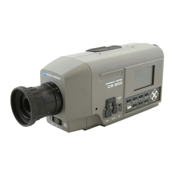
- Page 1 CHROMA METER CS-200 Instruction Manual Please read before using this instrument.
-
Page 2: Safety Symbols
• Every effort has been made in the preparation of this manual to ensure the accuracy of its contents. However, should you have any questions or find any errors, please contact the nearest Konica Minolta-authorized service facility. • KONICA MINOLTA will not accept any responsibility for consequences arising from the use of the instrument. -
Page 3: Safety Precautions
Should either of these happen, switch power off and unplug AC adapter immediately. If used on batteries, remove them and contact the nearest Konica Minolta-authorized service facility. Do not dispose of batteries in fire, short their terminals, apply heat to them or disassemble them. - Page 4 Use this instrument near AC outlet for easy plugging or unplugging in using AC adapter. Do not use batteries other than those specified by KONICA MINOLTA. Do not use new and old batteries together or combine different type batteries. When installing batteries in instrument, make sure that they are correctly oriented according to (+) and (-) marks.
-
Page 5: Introduction
This is delicate measurement instrument. Use packaging materials supplied in pur- chasing in case this instrument needs to be transferred for such purpose as main- tenance in KONICA MINOLTA's factories. These packaging materials are useful for minimizing shock or vibration to this instrument in such situation. Use holding cap for the same purpose especially to protect optical system of this instrument. -
Page 6: This Instrument
• Should this instrument break down, do not try to disassemble and repair it by your- self. Please contact the nearest Konica Minolta-authorized service facility. • Warm this instrument up for 15 minutes at least after switching power on when the luminance is 10 cd/m or lower (measuring angle 1˚). -
Page 7: Storage
Maintenance • Periodical checkup is recommended annually to maintain measurement accuracy of instrument. For details on checkup, please contact the nearest Konica Minolta-autho- rized service facility. Disposal Method • Make sure that the instrument, all accessories (including any used batteries), and the packing materials are either disposed of or recycled correctly in accordance with local laws and regulations. -
Page 8: Table Of Contents
INDEX Safety Precautions …………………… 2 Installing Introduction …………………………… 3 Installing ……………………………… 20 Note on Use …………………………… 3 Hand Strap …………………………… 21 Operating Environment ……………………… 3 Adjusting hand strap ……………………… 21 This Instrument ……………………………… 4 How to carry………………………………… 21 Backup Battery ……………………………… 4 Notes on carrying …………………………... - Page 9 Buzzer Setting ………………………… 52 Backlight ON/OFF …………………… 54 Communication Setting Sleep Mode ………………… 56 Connecting to PC …………………… 98 Setting Internal Clock ……………… 58 Remote Mode ………………………… 99 Measurement Preparation Description Calibration …………………………… 62 Principle of Measurement ……… 102 Calibration Channel …………………… 62 Spectral Fitting Method ……………...
-
Page 10: Standard Accessory
Standard Accessory Standard and optional accessories are available with the instrument. ∗ The shape of some products may be different from those shown. Lens Cap • Attached to objective lens for protecting it when not using this instrument. Holding Cap CS-A24 •... -
Page 11: Optional Accessories
Optional Accessories Close-Up lens No.107 Close-Up lens No.122 • Placed before objective lens for measure- ment of small object. ND Filter (1/10) CS-A6 ND Filter (1/100) CS-A7 • Placed before objective lens for measure- ment of high luminance object, but sand- wich step up ring (40.5 to 55 mm) CS-A26 inbetween. - Page 12 Soft Case CS-A23 • Used to keep this instrument and accesso- ries or carry them with hand. Never use for transfer. Data Management Software CS-S10w Professional • Enables multiple data management thanks to additional functions to that for CS-S10w Standard.
-
Page 13: System Configuration
System Configuration Standard accessories Optional accessories AA-Size Batteries (x4) (commercially available) Lens Cap Step Up Ring CS-200 (40.5-55mm) ND Eyepiece CS-A26 Filter AC-A27 TARGET COLOR PEAK/VALLEY SHUTTER MEMORY MEAS SPEED ABS/DIFF BACKLIGHT ND Filter KEY LOCK CHAR MODE RECALC SHIFT ENTER MENU (1/10)CS-A6... -
Page 14: Names And Functions Of Parts
Names and Functions of Parts Names of Each Part LCD screen Focus distance scale Objective lens Key panel Power switch AC adapter input terminal Focus adjustment ring USB connector Measuring angle selector Protect cover Finder Measurement button Diopter adjustment ring Hand strap Inside Finder Screw hole for fixing... -
Page 15: Functions Of Each Part
Functions of Each Part Power switch:(p.23) Switches this instrument on/off. (|) for ON; (O) for OFF AC adapter input terminal:(p.23) To which accessory AC adapter is connected. USB connector: (p.98) To which USB cable is connected when used with PC. Measuring angle selector: (p.88) Used to select measuring angle among 1˚, 0.2˚... -
Page 16: Key Panel
Key Panel Main Functions of Each Key ① MEMORY Measured data is stored in memory by pressing this key when measurement screen and save screen appears. ② MEAS SPEED Measurement time is switched in order AUTO → LTD. AUTO → Super-FAST →FAST → SLOW → Super-SLOW → MANUAL →... -
Page 17: Shift Mode
SHIFT mode Press ➎ SHIFT key to switch between SHIFT mode and normal mode. In SHIFT mode, keys from ➊ to ➍ , ➏ and ➑ become valid; in normal mode, keys from ① to ④, ⑥ and ⑧ become valid. Keys of ⑤, ⑦ and ➎ are always valid either in SHIFT mode or normal mode. -
Page 18: Indicator Inside Finder
Indicator Inside Finder 1˚Aperture value appears 0.2˚ Aperture on in-finder indicator. K (displayed as ) and M (displayed as ) show and x10 respectively. 0.1˚ Aperture... -
Page 19: Diopter Adjustment
Diopter Adjustment Rotate diopter adjustment ring for adjustment of diopter. Diopter adjustment ring Adjust so that A or B on aperture or black circle indicating measuring area looks clear when ob- serving object through finder. Adjustment would be easy starting with 1˚ aper- ture where object near aperture looks blur. -
Page 20: Lcd Screen
Setting status in this instrument is dis- LCD Screen played. Measurement Screen <ANGL> Currently selected measuring angle is displayed.(1°,0.2°,0.1°)(p.88) CH ID name(p.74) <SPD> Currently selected measuring time is displayed.(AUTO,LTD.AUTO, S-FAST, Calibration channel(p.62) FAST, SLOW, S-SLOW, MANU)(p.28) <SYNC> Synchronization frequency is displayed <PEAK>... - Page 21 Installing...
-
Page 22: Installing
Installing Use screw hole for fixing at the bottom of this instrument if utilized with tripod or jig. 2 type holes are available. Tripod screw hole : To set on tripod. Screw depth is 6.5 mm. ISO screw hole : To set on jig. Use ISO screw with top diameter of 5mm and depth of 6.5 mm. -
Page 23: Hand Strap
Hand Strap Hand strap can be used to carry this instrument with hand. Adjusting hand strap Insert your right hand between this instrument and hand strap, and adjust hand strap so that your hand securely fits to the instrument without any gap. How to carry As shown in the figure, insert your right hand through hand strap and support the bottom close to objective lens with your left hand. -
Page 24: Connecting Ac Adapter
Doing so may cause fire. In such situations, switch power off immediately, unplug AC adapter (or remove batteries in using ones) and contact the nearest Konica Minolta-authorized ser- vice facility. (Failure to adhere to following points may result in injury or Caution damage to instrument or other property.) -
Page 25: Connection Method
Connection Method Make sure that power switch is OFF (slided to [O] mark side). Lift protect cover and connect AC adapter plug to AC adapter input terminal on body. Plug AC adapter to outlet (AC 100V-120V or 200-240V , 50 Hz/60 Hz). ■■■■■■■■■■■■ ... -
Page 26: Placing Batteries
Caution damage to instrument or other property.) Do not use batteries other than those specified by KONICA MINOLTA. Or do not use new and old batteries together or combine different type batteries. When installing batteries in this instrument, make sure that they are correctly placed according to (+) and (-) marks. -
Page 27: Placing Batteries
Placing Batteries Make sure that power switch is OFF (slided to [O] mark side). Open battery chamber cover while pressing and sliding mark to the direction shown in illustration. Place 4 AA size batteries following polarity indication in battery chamber. Do no touch or short terminals in battery chamber. -
Page 28: On(|)/Off(O) Of Power Switch
ON(|)/OFF(O) of Power Switch To secure accurate measurement in either of following situations, 15-minute warm-up is recommended at least. 1. Measuring low luminance light source object: At 2856K (Standard light source A) as measuring stick 10 cd/m or lower (1˚ Aperture) 250 cd/m or lower (0.2˚... -
Page 29: Setting
Setting... -
Page 30: Selecting Measurement Time
Selecting Measurement Time Select measurement time depending on purpose. 7 modes are available for measurement time. Select the mode with long measurement time when repeated accuracy is required such as when measuring object of low luminance. ∗ Setting at the shipment from factory : AUTO. Measurement Time calculated by formula Time for integration (Time for integration x 2 +Time to open/close... - Page 31 < > Press MEAS SPEED key to select < > ANGL 1° VIEW CH00: DEFAULT < > MANU: 1 measurement speed. < > Lv ------ SYNC NO SYNC < > cd/m LENS STANDARD x ------ < > <SPD> switches in order of AUTO → LTD.AUTO AUTO NUM <...
-
Page 32: Internal Sync Measurement Mode Setting
Internal Sync Measurement Mode Setting Internal sync measurement mode refers to measurement mode where measurement is made in the same timing as periodical light source pulse frequency, such as vertical syn- chronization frequency for display. ∗ Setting at the shipment from factory : NO SYNC Operation Procedure 5, 7 1, 10... - Page 33 < > Press either key to move SYNC MODE inversion cursor from [NO SYNC] to [SYNC] so that light source NO SYNC 60.00Hz pulse frequency can be entered. (SYNC) Press either OK: [ENTER] CANCEL: [ESC] [ 2° ] to set arbitrary value. <...
-
Page 34: Setting Observer
Setting Observer Color matching function for chromaticity calculation is selectable between 2˚ and 10˚. ∗ Setting at the shipment from factory : 2˚ OBS Operation Procedure 1, 7 4, 5 < > Press key when menu or target < > ANGL 1°... - Page 35 < > Press either key to set MENU either for [2˚OBS] or [10˚OBS]. OBSERVER 10˚ OBS Press ESC key to stop. BREAK : [ESC] [ 2° ] < > ENTER Press key. MENU OBSERVER 10˚ OBS After “PLEASE WAIT...” appears, inversion cursor moves from [OBSERVER] to right to change observer angle.
-
Page 36: Selecting Color Space
Selecting Color Space See below table for available color space. ∗ Setting at the shipment from factory : L Color space LCD Screen Display Description Displayed and output in luminance L and chro- xy ∗1 < > < > maticity coordinates x,y. CH00: DEFAULT ANGL... - Page 37 Operation Procedure < > Press key when menu or target < > ANGL 1° VIEW CH00: DEFAULT < > AUTO value setting menu appears. Lv ------ < > SYNC 200.00Hz < > cd/m LENS STANDARD x ------ < > Measurement screen appears on LCD screen. AUTO NUM <...
-
Page 38: Selecting Absolute Value (Abs)
Selecting Absolute Value (ABS)/Difference (DIFF) Display Whether chromaticity value is shown in absolute (ABS) or difference (DIFF) is selectable. See below table for each case. ∗ Setting at the shipment from factory : Absolute value (ABS) Color Space Switching between Absolute Value (ABS) and Difference (DIFF) Dominant wavelength ・x・y ・... - Page 39 Operation Procedure < > Press key when menu or target < > ANGL 1° VIEW CH00: DEFAULT < > AUTO value setting menu appears. Lv ------ < > SYNC 200.00Hz < > cd/m LENS STANDARD x ------ < > Measurement screen appears on LCD screen. AUTO NUM <...
-
Page 40: Selecting Digit For Chromaticity Display
Selecting Digit for Chromaticity Display This is selectable either 4 or 3. If measurement value on LCD screen is illegible because of blinking, set for 3 digits. ∗ Setting at the shipment from factory : 4 FIGURES Operation Procedure 1, 7 4, 5 < > Press key when menu or target < > ANGL 1° VIEW CH00: DEFAULT < >... - Page 41 < > Press either key to set for MENU either [4 FIGURES] or [3 FIGURES]. OBJECTIVE LENS STANDARD DISPLAY DIGITS 3 FIGURES Press ESC key to stop. MEMORY MODE AUTO NUM DATA PROTECT BREAK : [ESC] [ 2° ] < >...
-
Page 42: Selecting Lens Type
Selecting Lens Type Use optional accessory close-up lens for small area measurement. See instruction manual for close-up lens for the placement of one. If close-up lens is to use, measurement value is required for calibration of lens transmission factor. Since calibration value varies depending on lens type, lens type has to be set in this instrument in advance. Erroneous setting causes incorrect measurement. Below table shows lens to set and setting for this instrument. Arbitrary lens like optional accessory ND Close-Up lens Close-Up lens Lens to Set No lens filter (1/10) CS-A6, ND Filter (1/100) CS-A7, No.107 No.122 Combination of close-up lens and ND filter Setting STANDARD No.107... - Page 43 < > Press MENU key twice. MENU OBJECTIVE LENS STANDARD Menu 2/4 screen appears on LCD screen. DISPLAY DIGITS 4 FIGURES MEMORY MODE AUTO NUM DATA PROTECT BREAK : [ESC] [ 2° ] < > Press either key to select MENU ENTER [OBJECTIVE LENS] and then...
-
Page 44: Selecting Single Or Continuous Measurement
Selecting Single or Continuous Measurement Here, measurement mode is selectable between “Single measurement” and “Continuous measurement”. Former means one measurement for one press and the latter continuous measurement from one press to another press of any key. In case of “Continuous mea- surement”, you can also view max and min values during continuous measurement when measurement is completed. - Page 45 < > Press either key to select MENU [MEAS MODE] and then ENTER key. CH SETTING MEAS MODE SINGLE Inversion cursor moves from [MEAS MODE] SYNC MODE to right to change measurement mode. DELETE BREAK : [ESC] [ 2° ] <...
-
Page 46: Selecting Of Max Or Minimum Value Display
Selecting of Max or Minimum Value Display Measurement result display is selectable among latest, max and minimum. If max <PEAK> or minimum <VALLEY> has been selected here, continuous measurement is to perform even though single measurement has been set. L determines max and min values. - Page 47 < > Press PEAK/VALLEY key to show < > ANGL 1° VIEW CH00: DEFAULT < > AUTO measurement mode to select. < > Lv 15.61 SYNC NO SYNC < > cd/m LENS STANDARD x 0.4125 < > Measurement screen switches in order of normal AUTO NUM <...
-
Page 48: Opening And Closing Of Finder Shutter
Opening and Closing of Finder Shutter To prevent light from finder from badly influencing measurement, internal shutter of finder is to close for every measurement. If observation through finder during measurement is required, setting can be changed not to close finder shutter. In this case, light from finder needs to be avoided by looking into finder during measurement. - Page 49 < > Press SHUTTER key. < > ANGL 1° VIEW CH00: DEFAULT < > AUTO < > Lv 92.74 SYNC NO SYNC Icon [ ] indicating "automatically closes for < > cd/m LENS STANDARD x 0.4185 < > every measurement" switches to icon [ ] AUTO NUM <...
-
Page 50: Setting Of Stored Data Protection
Setting of Stored Data Protection Whether warning message appears or not is selectable for the case to store data in the memory channel with measurement value. ∗ Setting at the shipment from factory : ON Operation Procedure 1, 7 4, 5 Press key when menu or target value setting menu appears. - Page 51 < > Press either MENU to set for [ON] or [OFF]. OBJECTIVE LENS STANDARD DISPLAY DIGITS 4 FIGURES If [ON] has been selected, a warning message MEMORY MODE AUTO NUM "OK TO OVERWRITE?" appears when trying DATA PROTECT to store data to the directory with existing data . BREAK : [ESC] <...
-
Page 52: Setting Of Update Method For Memory Channel
Setting of Update Method for Memory Channel to Store Measurement Value There are 100 directories to store measurement value from M000 to M100 and each can store one value, therefore 101 in total. Here, whether measurement value is to store automatically or by pressing MEMORY key is selectable for every measurement. - Page 53 < > Press either MENU to switch update method of OBJECTIVE LENS STANDARD measurement value directory. DISPLAY DIGITS 4 FIGURES key is pressed, mode switches in order of [AUTO MEMORY MODE AUTO NUM NUM] → [AUTOSAVE] → [MAN NUM] → [AUTO DATA PROTECT NUM].
-
Page 54: Buzzer Setting
Buzzer Setting This instrument usually generates buzzer sound for key operation, but setting for buzzer sound is switchable. Buzzer for measurement, operation, and error can be set indepen- dently. ∗ Setting at the shipment from factory : ON for MEASUREMENT, OPERATION, and WARNING Operation Procedure 1, 9 4, 5, 6... - Page 55 < > Press either key to BUZZER select parameter to change MEASUREMENT and then press ENTER key. OPERATION Inversion cursor moves from parameter name WARNING to right to change setting for buzzer sound. BREAK : [ESC] [ 2° ] < >...
-
Page 56: Backlight On/Off
Backlight ON/OFF Whether turning backlight on LCD is ON or OFF is selectable. ∗ Setting at the shipment from factory : ON Operation Procedure < > Press key when menu or target < > ANGL 1° VIEW CH00: DEFAULT < >... -
Page 58: Setting Sleep Mode
Setting Sleep Mode Sleep mode can be set for saving electric power consumption for the case that key has not been operated or communication has not been done for more than 30 minutes. ∗ Setting at the shipment from factory : OFF Operation Procedure 1, 7 4, 6... -
Page 59: Sleep Mode
< > Press either to set MENU either for [ON] or [OFF]. SLEEP MODE DATE & TIME If [ON] is set, this instrument operates in sleep BUZZER mode when key operation or communication has not been done for more than 30 minutes. VERSION "SLEEP MODE"... -
Page 60: Setting Internal Clock
Setting Internal Clock This instrument is equipped with internal clock to record measurement time. Although measurement date and time are not indicated in this instrument, one can be output together with measurement value when this unit is controlled with PC. If used with either standard accessory data management software CS-S10w Standard or optional CS-S10w Professional, measurement time is to display together with measure- ment value. - Page 61 < > Press either to select MENU [DATE & TIME] and then ENTER key. SLEEP MODE DATE & TIME < DATE & TIME > screen appears. BUZZER VERSION BREAK : [ESC] [ 2° ] < > Press either DATE & TIME set arbitrary value.
-
Page 63: Measurement Preparation
Measurement Preparation... -
Page 64: Calibration
L T∆uv, XYZ, and dominant wavelength in one channel. CH00 is for measurement based upon KONICA MINOLTA’s calibration standard. Its cali- bration correction coefficient has been set and is unchangeable. Only target color and CH ID name settings are available. -
Page 65: User Calibration
Keep calibration light source as stable as possible with fixed voltage power source during measurement. User calibration can be applied to every channel except for CH00. KONICA MINOLTA’s correction coefficient has been set in all channels including CH00 by the time of shipment. This shall restore if user calibration is reset. -
Page 66: Implementing User Calibration
Implementing User Calibration User calibration cannot be conducted in calibration channel CH00. (CH00 serves as calibration channel for measurement based on KONICA MINOLTA's calibration standard.) When user calibration is performed in the calibration channel for which target color has already been set, previous target color is cancelled. - Page 67 < > Press SHIFT key to cancel SHIFT mode. < > ANGL 1° VIEW CH01: DEFAULT < > AUTO < > Lv ------ SYNC NO SYNC < > cd/m LENS STANDARD x ------ < > AUTO NUM < > y ------ MEMORY DATA M000 :(NO DATA) Lv ------...
-
Page 68: Through Measurement
(CH00) based upon LENS STANDARD cd/m < > x ------ AUTO NUM KONICA MINOLTA's calibration standard. <CURRENT DATA> y ------ Measurement value appears on 90.30 SELECT MEH DATA <CURRENT DATA> part of LCD screen x 0.4210 OR MEASURE. - Page 69 < > <USER CAL DATA> ANGL 1° VIEW < > ENTER CH01:<DEFAULT> AUTO Press key. < > SYNC NO SYNC Lv ------ < > LENS STANDARD cd/m Calibration entry screen appears. < > x ------ AUTO NUM y ------ <CURRENT DATA> 90.30 SET CAL VALUE.
-
Page 70: Through Selection From Saved Data
< > Please select data which was measured using x ------ AUTO NUM CH00 (KONICA MINOLTA’ s calibration standard.) y ------ <MEMORY DATA> M002 SELECT MEH DATA 100.76 The data are considered to have been calculated using CH00 (KONICA OR MEASURE. - Page 71 < > Enter value for calibration. <USER CAL DATA> ANGL 1° VIEW < > CH01:<DEFAULT> AUTO < > key: 0 to 9 in ascending order. K, M, SYNC NO SYNC Lv 1----- < > LENS STANDARD cd/m < > decimal point and space available. If kept x ------ AUTO NUM y ------...
-
Page 72: Copy From Other Calibration Channel
continuation from a p.64, 65. 7, 8 (3) Copy from other calibration channel Press either key to select < > CH SETTING < > ENTER CH02: DEFAULT [CH COPY] and then key. USER CAL < COPY TO ??> screen appears. CH ID NAME CH COPY CH RESET... -
Page 73: Numerical Value Entry Ranges
You can return to procedure continue copying other channel. Note that original calibration channel appears when you return to measurement screen in procedure < > < > ANGL 1° VIEW DEFAULT < > AUTO Press key three times to < >... -
Page 74: Reset User Calibration
Reset User Calibration User calibration can be reset channel by channel. KONICA MINOLTA’s calibration is to apply to channel for which user calibration has been reset. Also, target color and ID name settings in the channel are to delete. Operation Procedure... - Page 75 < > Press MENU key. MENU CH SETTING Menu 1/4 screen appears on LCD screen. MEAS MODE SINGLE SYNC MODE DELETE BREAK : [ESC] [ 2° ] Press either key to select < > CH SETTING < > ENTER <CH SETTING> and then key.
-
Page 76: Setting Ch Id Name
Setting CH ID Name CH ID name indicates name given to each calibration channel by entering characters. CH ID name appears on LCD screen in measurement together with calibration channel. It is helpful if for which object user calibration or target color setting has been done is entered. - Page 77 < > Press SHIFT key to cancel SHIFT mode. < > ANGL 1° VIEW CH01: DEFAULT < > AUTO < > Lv ------ SYNC 60.00Hz < > cd/m LENS STANDARD x ------ < > AUTO NUM < > y ------ MEMORY DATA MOOO:(NO DATA) Lv ------...
- Page 78 Press key to move cursor < > CH ID NAME < > to second digit position. CH01: DEFAULT [ SDEFAULT ) ] Lv ------ x ------ y ------ : [ENTER] [ 2° ] Repeat procedures from < > CH ID NAME <...
-
Page 79: Entering Character
Entering Character If you press SHIFT key to switch to SHIFT mode and then CHAR MODD key when screen to enter calibration channel ID and measurement value ID of stored data in appears, available character type for entry shifts in order of Capital Alphabet → Small Alphabet →... -
Page 80: Setting And Changing Target Color
Setting and Changing Target Color Target color Target color serves as reference for measurement of deviation of measured color from reference. It can be set channel by channel. Setting methods are as follows: (1) User calibration: Calibration value is simultaneously set as target color in user calibration. (2) Measurement (3) Select from stored data (4) Enter numerical value... -
Page 81: Through User Calibration
CH01 to CH20. No further target color setting is needed if target color has been fixed for calibration channel. Follow below next page only when target color set in CH01 to CH20 needs to change or target color is needed to set in KONICA MINOLTA’s calibration standard CH00. -
Page 82: Through Measurement
(2) Through measurement Operation Procedure 1, 8 < > Press key when menu or target < > ANGL 1° VIEW CH01: DEFAULT < > AUTO value setting menu appears. Lv ------ < > SYNC NO SYNC < > cd/m LENS STANDARD x ------ <... - Page 83 Use close-up lens, select measuring angle, adjust finder diopter and focus. For more details on each operation, see p.88. < > Press Measurement button <TARGET> ANGL 1° VIEW < > :Display * 1 AUTO to start measurement. < > SYNC NO SYNC Lv ------ <...
-
Page 84: Through Selection From Saved Data
(3) Through selection from saved data Operation Procedure 2, 5 1, 8 3, 6 < > Press key when menu or target < > ANGL 1° VIEW CH01: DEFAULT < > AUTO value setting menu appears. Lv ------ < > SYNC NO SYNC <... - Page 85 < > Press SHIFT key to cancel SHIFT mode. <TARGET> ANGL 1° VIEW < > CH01 :Display * 1 AUTO < > SYNC NO SYNC Lv ------ < > LENS STANDARD cd/m < > x ------ AUTO NUM y ------ <HOLD DATA>...
-
Page 86: By Entering Numerical Value
(4) By entering numerical value Operation Procedure 4, 5 1, 10 3, 6 < > Press key when menu or target < > ANGL 1° VIEW CH01: DEFAULT < > AUTO value setting menu appears. Lv ------ < > SYNC NO SYNC <... - Page 87 < > Press TARGET key to go to <TARGET> ANGL 1° VIEW < > CH01:Display * 1 AUTO target color entry screen. < > SYNC NO SYNC Lv ------ < > LENS STANDARD cd/m < > x ------ AUTO NUM y ------ Enter target color in numerical value.
-
Page 89: Measurement
Measurement... -
Page 90: Measuring Distance And Measuring Area
Measurement Operation Procedure Decide whether you use close-up lens (optional) or not according to measuring object size and distance. See the table below for details on measuring distance and measuring area. If you set close-up lens, lens type setting is required in this instrument. (see p.40) Measuring distance and measuring area (unit:mm) Minimum measuring... - Page 91 < > Press key when menu or target < > ANGL 1° VIEW CH01: DEFAULT < > AUTO value setting menu appears. Lv ------ < > SYNC 200.00Hz < > cd/m LENS STANDARD x ------ < > Measurement screen appears on LCD screen. AUTO NUM <...
-
Page 92: Storing Measurement Value
Storing Measurement Value There are 100 directories to store measurement value from M000 to M100 and each can store one value, 101 in total. If memory channel update method has been set for [AUTO- SAVE], measurement value is to store after measurement automatically. In case of [AUTO NUM] or [MAN NUM], follow below procedure to store measurement value. - Page 93 < > Press MEMORY key. < > ANGL 1° VIEW CH01: DEFAULT < > AUTO < > Lv 20.80 If [MAN NUM] has been set for memory SYNC 60.00Hz < > cd/m LENS STANDARD x 0.4476 < > channel update, measurement value AUTO NUM <...
-
Page 94: Displaying Stored Data And
Displaying Stored Data and Setting Measurement Value ID Name Follow below procedures to display stored data. Operation Procedure 1, 4 5, 9 4, 6 < > Press [ESC] key when menu or < > ANGL 1° VIEW CH00: DEFAULT < >... - Page 95 appears. Stored data is displayed on the condition when measurement was made. However, converted form in current color space for this instrument appears for color space. To return to measurement screen, press either ,or ESC key. Measurement value ID Name can be given to stored data. Measurement value ID Name refers to name to each stored data by entering characters.
-
Page 96: Deleting Stored Data
Deleting Stored Data Follow below procedures to delete stored data. Operation Procedure 1, 8 4, 6, 7 4, 5 < > < > Press key when menu or target ANGL 1° VIEW CH00: DEFAULT < > AUTO < > Lv ------ value setting menu appears. - Page 97 < > Press either key to <DELETE> ANGL 1° VIEW < > AUTO select channel number of which < > SELECT DATA SYNC NO SYNC < > LENS STANDARD stored data is to delete. < > M009 AUTO NUM Press key and move cursor to [ALL] to delete <MEMORY DATA>...
-
Page 99: Communication
Communication... -
Page 100: Connecting To Pc
Connecting to PC This instrument can be used together with PC for mutual communication. Use USB cable (2m) IF-A33 supplied as standard accessory for this purpose. USB cable is allowed to plug/unplug while power is on, but it is recommended to switch power off in this case. -
Page 101: Remote Mode
See instruction manual of CS-S10w Standard for details on the spec and usage. If you want to use independent program in PC to control this instrument, download Com- munication Specifications from KONICA MINOLTA’s website at URL below for your refer- ence. -
Page 103: Description
Description... -
Page 104: Principle Of Measurement
Principle of Measurement Spectral Fitting Method Konica Minolta’s newly-developed spectral fitting method provides tristimulus values (XYZ = red, green, blue) with significantly higher accuracy than that of conventional tris- timulus colorimeters. This is achieved by using the output from 40 sensors to calculate the spectral response corresponding to human eye sensitivity (CIE 1931 color-matching functions). -
Page 105: L V T∆Uv
T∆uv Following factors can be acquired as measurement value with LvT(d)uv as color space of this instrument. : Luminance : Correlated color temperature : Color difference from blackbody locus ∆uv While L stands for luminance, T and ∆uv for color in L T∆uv. -
Page 106: Dominant Wavelength
Dominant Wavelength In the x, y chromaticity diagram shown below, the curve VS SR is the spectrum locus, and point N is the white point. Colors located in the region enclosed by the spectrum locus and the straight lines VN and NR are referred to as spectral colors;... - Page 107 Spectrum locus 550 nm 500 nm 600 nm White point 780 nm Pure purple line 380 nm Dominant wavelength on chromaticity diagram...
-
Page 108: Measurement Of Object Color
Measurement of Object Color This instrument can perform simple measurement by utilizing user calibration function. This is also available by using standard accessory data management software CS-S10w Standard or optional CS-S10w Professional. Measured data is evaluated based on lumi- nance which has been stored as light source data in CS-S10w. See instruction manual of CS-S10w for details. -
Page 109: Operation Procedure
Operation Procedure (Without data management software CS-S10w) Setting Necessary for Object Color Measurement Set one or more tungsten lumps Illumination or equivalent as illumination Light Source White calibration plate source toward white calibration plate as in the right illustration. • Set this instrument vertical 45°... -
Page 110: Operation Procedure
Operation Procedure (With data management software CS-S10w) Setting Necessary for Object Color Measurement Set one or more tungsten lumps Illumination or equivalent as illumination Light Source White calibration plate source toward white calibration plate as in the right illustration. • Set this instrument vertical 45°... -
Page 111: Outer Dimensions
Outer Dimensions (Unit: mm) Filter thread diameter ø40.5 Standard plane for distance measurements For tripod screw (depth:6.5) Optical axis For M5 screw For M5 screw (depth:6.5) (depth:6.5) 61.6... -
Page 112: Error Messages
Error Messages Error message appears on LCD screen for incorrect operation of this instrument through key. Below table shows type of error message, its description and corrective action respectively. Error message Cause (Description) Corrective Action BATTERY OUT Battery voltage decreases. •... - Page 113 Error message Cause (Description) Corrective Action OVER Luminance of measuring • Use ND filter and redo measure- object is higher than avail- ment. able measurement range. • If symptom does not improve, please contact the nearest Konica Minolta-authorized service facility. OFFSET ERROR Zero calibration has not •...
- Page 114 Error message Cause (Description) Corrective Action MEMORY Data stored in ROM is • Do not switch OFF (O side) while ERROR broken, or backup batteries storing data or changing setting, or drain. when message “PLEASE WAIT…” appears. • Switch ON (| side) to charge back- up battery.
-
Page 115: Error Check
Should error be found in this instrument, try corrective actions shown in the following table. If this does not help, this instrument has possibly been broken. Please contact the nearest Konica Minolta-authorized service facility with error number and version of your instrument. Version can be identified in procedure on p.116. - Page 116 Error Page to Symptom Item to Check Corrective Action Refer Measure- Does data exist? This appears when there is no data ment value in measurement value, stored data, appears as calibration value and target color. “------“. Doesn’t color space This appears when color tempera- become color tempera- ture cannot be converted for display.
- Page 117 For replacing backup battery, please contact the nearest Konica Minolta- authorized service facility. Same error Check corrective action If symptom does not improve, please message ap- for error message.
-
Page 118: Identifying Version
Identifying Version Operation Procedure 1, 5 < > Press key when menu or target < > ANGL 1° VIEW CH00: DEFAULT < > AUTO value setting menu appears. < > Lv 20.80 SYNC 200.00Hz < > cd/m LENS STANDARD x 0.4476 <... - Page 119 < > Press key twice to return MENU to measurement screen. SLEEP MODE DATE & TIME BUZZER VERSION BREAK : [ESC] [ 2° ] < > VERSION VER. 1.00.0000 0000000 BREAK : [ESC] [ 2° ] < > < > ANGL 1°...
-
Page 120: Changing Luminance Unit (Cd/M 2 /Fl)
Changing Luminance Unit (cd/m / fL ) You can select [cd/m ] or [ fL ] as luminance unit. Operation Procedure < > Follow procedures from VERSION “Ident ifying Version”(p.118) to display <VERSION> screen on LCD screen. VER. 1.00.0000 0000000 BREAK : [ESC] [ 2°... - Page 121 < > Press ENTER key. VERSION <VERSION> screen appears on LCD screen. VER. 1.00.0000 0000000 BREAK : [ESC] [ 2° ] < > Press key twice. < > ANGL 1° VIEW CH00: DEFAULT < > AUTO < > 6.07 SYNC 200.00Hz Measurement screen appears on LCD screen.
-
Page 122: Specification
Power source AC adapter and 4 AA-Size Batteries Battery life 3 hours approx. (in Continuous measurement/FAST mode, with AA-Size bat- tery under company testing KONICA MINOLTA’s conditions.) Size 95 (W) x 127(H) x 334(L) mm Weight 1.8 kg (without battery) Operating temperature 0 to 40˚C, RH 85 % or less (at 35˚C) with no condensation... - Page 123 < CAUTION > KONICA MINOLTA WILL NOT BE LIABLE FOR ANY DAMAGES RESULTING FROM THE MISUSE, MISHANDLING, UNAUTHORIZED MODIFICATION, ETC. OF THIS PRODUCT, OR FOR ANY INDIRECT OR INCIDENTAL DAMAGES (INCLUDING BUT NOT LIMITED TO LOSS OF BUSINESS PROFITS, INTERRUPTION OF BUSINESS, ETC.) DUE TO...
- Page 124 ©2005 KONICA MINOLTA, INC. 9222-1892-A1 BIIBPK Printed in Japan...
Need help?
Do you have a question about the CHROMA METER CS-200 and is the answer not in the manual?
Questions and answers