Table of Contents
Advertisement
Quick Links
Advertisement
Table of Contents

Related Manuals for AXIOMTEK eBOX100-51R-FL Series


Summary of Contents for AXIOMTEK eBOX100-51R-FL Series
- Page 1 Series Embedded System User’s Manual...
-
Page 2: Disclaimers
Axiomtek does not make any commitment to update any information in this manual. Axiomtek reserves the right to change or revise this document and/or product at any time without notice. No part of this document may be reproduced, stored in a retrieval system, or transmitted in any forms or by any means, electronic, mechanical, photocopying, recording, among others, without prior written permissions of Axiomtek Co., Ltd. -
Page 3: Safety Precautions
Safety Precautions Before getting started, please read the following important safety precautions. The eBOX100-51R-FL does not come with an operating system which must be loaded first before installation of any software into the computer. Be sure to ground yourself to prevent static charge when installing any internal components. -
Page 4: Classifications
Classifications Degree of production against electric shock: not classified Degree of protection against ingress of water: IP40 Equipment not suitable for use in the presence of a flammable anesthetic mixture with air, oxygen or nitrous oxide. Mode of operation: Continuous... -
Page 5: General Cleaning Tips
General Cleaning Tips Please keep the following precautions in mind while understanding the details fully before and during any cleaning of the computer and any components within. A piece of dry cloth is ideal to clean the device. Be cautious of any tiny removable components when using a vacuum cleaner to absorb dirt on the floor. -
Page 6: Scrap Computer Recycling
Scrap Computer Recycling Please inform the nearest Axiomtek distributor as soon as possible for suitable solutions in case computers require maintenance or repair; or for recycling in case computers are out of order. Trademarks Acknowledgments Axiomtek is a trademark of Axiomtek Co., Ltd. -
Page 7: Table Of Contents
Table of Contents Disclaimers ......................ii Safety Precautions ....................iii Classifications ....................... iv General Cleaning Tips ................... v Scrap Computer Recycling ................... vi SECTION 1 INTRODUCTION ................ 1 General Descriptions ................. 1 System Specifications ............... 2 1.2.1 CPU ........................2 1.2.2 I/O System ...................... - Page 8 SECTION 4 BIOS SETUP UTILITY .............. 31 Starting ..................... 31 Navigation Keys ................31 Main Menu ..................32 Advanced Menu ................33 Chipset Menu ................... 44 Security Menu .................. 48 Save & Exit Menu ................50 APPENDIX A WATCHDOG TIMER .............. 53 About Watchdog Timer ..................
-
Page 9: Section 1 Introduction
Series user’s Manual SECTION 1 INTRODUCTION This section contains general information and detailed specifications of the eBOX100-51R-FL.Section 1 consist of the following sub-sections: General Descriptions System Specifications Dimensions I/O Outlets Packing List Model List 1.1 General Descriptions... -
Page 10: System Specifications
Series user’s Manual Features ® ® Core™ i5-7300U 2.6 GHz /Intel® Celeron Intel 3965U 2.2 GHz One DisplayPort to support 4K resolution Intel® AMT 11 supported M.2 Key E 2230 for W i-Fi M.2 Key B 2242 for storage ... -
Page 11: I/O System
Series user’s Manual 1.2.2 I/O System DisplayPort 1 x DisplayPort++, DisplayPort 1.2 to support 4096× 2160 @ 60Hz Ethernet 2 x 10/100/1000 Ethernet ports (i211AT,i219LM) Intel i219LM supports 1000/100/10Mbps Gigabit/Fast Ethernet with W ake ®... -
Page 12: System Specifications
Series user’s Manual 1.2.3 System Specifications Watchdog Timer 1~255 seconds or minutes; up to 255 levels. Power Supply 12VDC Optional 12V/60W AC to DC adapter Operation Temperature -10°C to +50°C (+14°F to +122°F) , with W .T. SSD & Memory ... -
Page 13: Driver Contents
Series user’s Manual 1.2.4 Driver Contents Please download system drivers and user’s manual from AXIOMTEK website. Chipset Graphic Ethernet ® Intel User Manual Quick Manual 【Note】: All specifications and images are subject to change without notice. -
Page 14: Dimensions
Series user’s Manual 1.3 Dimensions The following diagrams show dimensions and outlines of the eBOX100-51R-FL. 1.3.1 System Dimensions Introduction... -
Page 15: Wall-Mount Bracket Dimensions
Series user’s Manual 1.3.2 Wall-mount Bracket Dimensions Introduction... -
Page 16: Din-Rail Kit Dimensions
Series user’s Manual 1.3.3 Din-Rail kit Dimensions Introduction... - Page 17 Series user’s Manual 1.3.4 VESA Mount Dimensions 【 】 Note : Please notice that eBOX100-51R only support vertical VESA mounting. Introduction...
-
Page 18: I/O Outlets
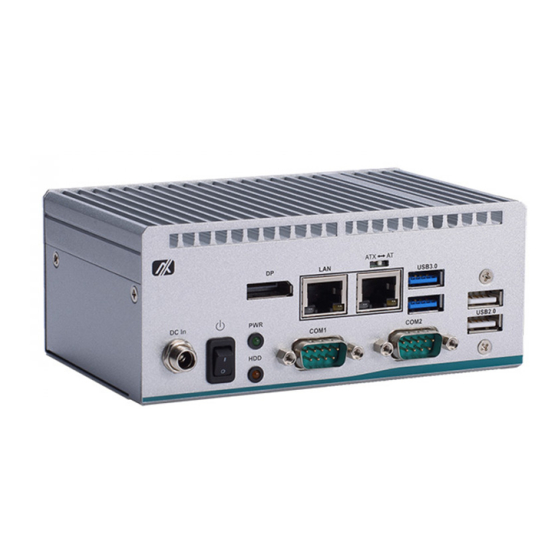
Series user’s Manual 1.4 I/O Outlets The following figures show I/O outlets on the eBOX100-51R-FL. Front View Rear View Introduction... -
Page 19: Packing List
Series user’s Manual 1.5 Packing List The eBOX100-51R-FL comes with the following bundle package: eBOX100-51R-FL System Unit x 1 Foot Pad x 4 Screw Pack x 1 Optional DDR4 SO-DIMM Memory Optional Wall-mount kit ... -
Page 20: Model List
(w/o adapter & power cord) ® Fanless ultra compact embedded system with Intel Celeron eBOX100-51R-DC-3965U 3965U,DisplayPort++, 2 GbE LANs, 2 COM and 4 USB (w/o adapter & power cord) Please contact Axiomtek’s distributors immediately in case any abovementioned items are missing. Introduction... -
Page 21: Section 2 Hardware Installation
Series user’s Manual SECTION 2 HARDWARE INSTALLATION The eBOX100-51R-FL is convenient for various hardware configurations, such as DRAM, M.2 Section 2 contain guidelines for hardware installation. 2.1 Installation of M.2 Storage Device The eBOX100-51R supports one M.2 2242 key B for M.2 SSD storage (SATA interface) Note: Please remove the DRAM before install the M.2 module if the system has installed... - Page 22 Series user’s Manual Step 5 Insert the M.2 SSD module firmly and secure the screw. Step 6 Put the bottom cover back and fasten all of screws to complete installation. Hardware Installation...
-
Page 23: Installation Of M.2 Wireless Module
Series user’s Manual 2.2 Installation of M.2 Wireless Module Step 1 Turn off the system and unplug the power cord. Step 2 Turn the system to the backside and then loosen two screws. Step 3 Slide away the bottom cover. -
Page 24: Installation Of Dram Module
Series user’s Manual 2.3 Installation of DRAM Module Step 1 Turn off the system and unplug the power cord. Step 2 Turn the system to the backside and then loosen tw o screws. Step 3 Slide away the bottom cover. -
Page 25: Section 3 Jumper & Connector Settings
Series user’s Manual SECTION 3 JUMPER & CONNECTOR SETTINGS Proper jumper settings configure the eBOX100-51R-FL to meet various application needs. Hereby all jumpers settings along with their default settings are listed for devices onboard. 3.1 Locations of Jumpers & Connectors... - Page 26 Series user’s Manual SCN2 SCN3 SCN4 SCN5 SSW1 Bottom side 【Note】: It is strongly recommended that any unmentioned jumper settings should not be modified without instructions by Axiomtek FAEs. Any modifications without instructions might cause system failure. Jumper & Connector Settings...
-
Page 27: Summary Of Jumper Settings
Series user’s Manual 3.2 Summary of Jumper Settings Proper jumper settings configure the eBOX100-51R-FL to meet various application purposes. A table of all jumpers and their default settings is listed below. Jumper and Switch Descriptions Settings Restore BIOS Optimal Defaults... -
Page 28: Restore Bios Optimal Defaults (Sw1)
Series user’s Manual 3.2.1 Restore BIOS Optimal Defaults (SW1) Use SW1 to clear CMOS. Press the tact switch for at least 3 second to restore BIOS optimal defaults. Functions Settings Normal (Default) Release Restore BIOS optimal defaults Press 3.2.2 Auto Power On (SSW1) If SSW1 (AT/ATX Switch) is enabled for power input, the system will be automatically power on without pressing soft power button. -
Page 29: Connectors
Series user’s Manual 3.3 Connectors Please refer to pin assignments below: Section Connectors Descriptions 3.3.1 Front Panel Connector 3.3.2 USB 2.0 Port 3 and 4 3.3.3 SMBus Connector 3.3.4 M.2 2242 Key B Connector 3.3.5 M.2 2230 Key E Connector 3.3.6... -
Page 30: Front Panel
Series user’s Manual 3.3.1 Front Panel This is a 2x6-pin header (pitch=2.0mm) for front panel interface. Signal Signal EXT SPK+ EXT SPK- PWR_PSON PWRLED- PWRLED+ PWRSW- PWRSW+ HW RST- HW RST+ HDDLED- HDDLED+ External Speaker Pin 1(+) and 2(-) connect the case-mounted speaker unit or internal buzzer cable. It is strongly recommended to connect with the matching cable, 594H3186800E. -
Page 31: Usb 2.0 Wafer Connector (Cn5)
Series user’s Manual 3.3.2 USB 2.0 Wafer Connector (CN5) The Universal Serial Bus (compliant with USB 2.0 (480Mbps)) connector is connected via cable from internal USB wafer connector (CN5). This is a 2x5-pin cut pin 9 (pitch=2.0mm) wafer connector, which is compliant with Hirose DF11-10DP- 2DSA, for installing versatile USB 2.0 compliant interface peripherals. -
Page 32: 2242 Key B Connector (Cn7)
Series user’s Manual 3.3.4 M.2 2242 Key B Connector (CN7) The CN7 is a M.2 Key B connector. It is suggested to install the M.2 storage module via SATA (Default) or PCIe x2 for NVMe (BOM Optional) with 22mm x 42mm (width x length). -
Page 33: 2230 Key E Connector (Cn8)
Series user’s Manual 3.3.5 M.2 2230 Key E Connector (CN8) The CN8 is a M.2 2230 Key E connector. It is suggested to install the M.2 wireless module via PCIe x1 with 22mm x 30mm (width x length). Signal Signal +3.3V_SBY... -
Page 34: Usb 3.0 Port (Cn10)
Series user’s Manual 3.3.6 USB 3.0 Port (CN10) The board comes with two Universal Serial Bus (compliant with USB 3.0 (5Gb/s)) type A connectors for installing USB peripherals such as keyboard, mouse, scanner, etc. Signal Signal USB_Data1- USB_Data2- USB_Data1+... -
Page 35: Displayport Connector (Cn13)
Series user’s Manual 3.3.8 DisplayPort Connector (CN13) The DisplayPort interface is available through connector CN13. Pins Signals DPB_LANE0 DPB_LANE0# DPB_LANE1 DPB_LANE1# DPB_LANE2 DPB_LANE2# DPB_LANE3 DPB_LANE3# Detect Pin DPB_AUX DPB_AUX# DPB_HPD +3.3V Jumper & Connector Settings... -
Page 36: Digital I/O Connector (Cn14)
Series user’s Manual 3.3.9 Digital I/O Connector (CN14) This is a 2x3-pin (pitch=2.0mm) connector. The system default doesn’t support DI/DO features, but the main board is reserved with a 4-bit digital I/O that meets requirements for a system customary automation control. The digital I/O can be configured to control cash drawers and sense warning signals from an Uninterrupted Power System (UPS), or perform store security control. -
Page 37: Com Wafer Connectors (Scn3 And Scn4)
Series user’s Manual 3.3.11 COM Wafer Connectors (SCN3 and SCN4) The system has two serial ports to support RS-232/422/485 for COM1 and COM2, these two COM ports is connected via 9-pin (pitch=1.25mm) connector which is compliant with Molex 53047-0910.The SCN3 and SCN4 are for COM2 and COM1 interfaces, respectively. For further information please refer to BIOS setting. -
Page 38: System Power Switch
Series user’s Manual 3.3.13 System Power Switch This button is for turning on/off the system power. 3.3.14 AC to DC Jack Power In Connector The system supports a DC12V DC-jack connector for system power input. Connect it to the power AC-DC 12V/60W adapter (optional) -
Page 39: Section 4 Bios Setup Utility
Series user’s Manual SECTION 4 BIOS SETUP UTILITY This section provides users with detailed descriptions in terms of how to set up basic system configurations through the BIOS setup utility. 4.1 Starting To enter the setup screens, follow the steps below: Turn on the computer and press the <Del>... -
Page 40: Main Menu
Series user’s Manual 4.3 Main Menu The Main Menu screen is the first screen users see when entering the setup utility. Users can always return to the Main setup screen by selecting the Main tab. System Time/Date can be set up as described below. -
Page 41: Advanced Menu
Series user’s Manual 4.4 Advanced Menu The Advanced menu also allows users to set configuration of the CPU and other system devices. Users can select any items in the left frame of the screen to go to sub menus: ►... - Page 42 Series user’s Manual Serial Port Configurations Users can use this screen to select options for the Serial Port Configuration, and change the value of the selected option. A description of the selected item appears on the right side of the screen.
- Page 43 Series user’s Manual Serial Port 1 Configuration Serial Port Enable or disable serial port 1. The optimal setting for base I/O address is 3F8h and for interrupt request address is IRQ4. COM Port Type Use this item to set RS-232/422/485 communication mode.
- Page 44 Series user’s Manual Serial Port 2 Configuration Serial Port Enable or disable serial port 2. The optimal setting for base I/O address is 2F8h and for interrupt request address is IRQ3. COM Port Type Use this item to set RS-232/422/485 communication mode.
- Page 45 Series user’s Manual Hardware Monitor This screen monitors hardware health status. This screen displays the temperature of system and CPU, system voltages (VBAT, +3.3V, +3.3V standby and +5V). BIOS Setup Utility...
- Page 46 Series user’s Manual ACPI Settings Use this screen to select options for the ACPI configuration, and change the value of the selected option. A description of the selected item appears on the right side of the screen. ACPI Sleep State Select the ACPI (Advanced Configuration and Power Interface) sleep state.
- Page 47 Series user’s Manual CPU Configurations This screen shows the CPU version and its detailed information. Intel Virtualization Technology ® Enable or disable Intel Virtualization Technology. When enabled, a VMM (Virtual Machine Mode) can utilize the additional hardware capabilities. It allows a platform to run multiple operating systems and applications independently, hence enabling a computer system to work as several virtual systems.
- Page 48 Series user’s Manual SATA Configurations In this Configuration menu, users can see the currently installed hardware in the SATA port. During system boot up, the BIOS automatically detects the presence of SATA device. SATA Mode Selection The SATA operation mode is AHCI (Advanced Host Controller Interface).
- Page 49 Series user’s Manual PCH-FW Configurations This screen displays ME Firmware information. BIOS Setup Utility...
- Page 50 Series user’s Manual AMT Configurations Use this screen to configure AMT parameters.. AMT BIOS Features Enable or disable Active Management Technology BIOS features. The default is Enabled. Note that this screen will be empty, if the CPU does not support Intel® AMT, see image below.
- Page 51 Series user’s Manual USB Configurations This screen is for BIOS flash utility. USB Devices Display all detected USB devices. BIOS Setup Utility...
-
Page 52: Chipset Menu
Series user’s Manual 4.5 Chipset Menu The Chipset menu allows users to change the advanced chipset settings. Users can select any of the items in the left frame of the screen to go to the sub menus: ► PCH-IO Configuration ►... - Page 53 Series user’s Manual PCH-IO Configuration This screen allows users to configure parameters of North Bridge chipset. BIOS Setup Utility...
- Page 54 Series user’s Manual HD Audio Configuration HD Audio subsystem configuration settings HD Audio Control detection of the HD Audio device. -Disabled: HDA will be unconditionally disabled. -Enabled: HDA will be unconditionally enabled. BIOS Setup Utility...
- Page 55 Series user’s Manual System AGENT (SA) Configuration This screen shows System Agent version information and provides function for specifying related parameters. Memory Configuration Use this item to refer to the information related to system memory. BIOS Setup Utility...
-
Page 56: Security Menu
Series user’s Manual 4.6 Security Menu Administrator Password This item indicates whether an administrator password has been set (installed or uninstalled). User Password This item indicates whether a user password has been set (installed or uninstalled). BIOS Setup Utility... - Page 57 Series user’s Manual Boot Menu The Boot menu allows users to change boot options of the system. Bootup NumLock State Use this item to select the power-on state for the keyboard NumLock. Boot Mode Use this option for boot mode settings.
-
Page 58: Save & Exit Menu
Series user’s Manual 4.7 Save & Exit Menu The Save & Exit menu allows users to load system configurations with optimal or fail-safe default values. Save Changes and Exit When users have completed the system configuration changes, select this option to leave Setup and return to Main Menu. - Page 59 Series user’s Manual Save Changes When completed the system configuration changes, select this option to save changes. Select Save Changes from the Save & Exit menu and press <Enter>. Select Yes to save changes. Discard Changes Select this option to quit Setup without making any permanent changes to the system configurations.
- Page 60 Series user’s Manual This page is intentionally left blank. BIOS Setup Utility...
-
Page 61: Appendix Awatchdog Timer
Series user’s Manual APPENDIX A WATCHDOG TIMER About Watchdog Timer Software stability is major issue in most applications. Some embedded systems are not watched by human for 24 hours. It is usually too slow to wait for someone to reboot when computer hangs. -
Page 62: Sample Program
Series user’s Manual Sample Program The following example enables configurations using debug tool. Enable WDT Enable configuration: O 2E 87; Un-lock super I/O O 2E 87 Select logic device: O 2E 07 O 2F 08 WDT device enable:...
Need help?
Do you have a question about the eBOX100-51R-FL Series and is the answer not in the manual?
Questions and answers