Table of Contents
Advertisement
Quick Links
Advertisement
Table of Contents

Related Manuals for AXIOMTEK EBOX800-841-FL Series


Summary of Contents for AXIOMTEK EBOX800-841-FL Series
- Page 1 Series Embedded System User’s Manual...
-
Page 2: Disclaimers
Axiomtek does not make any commitment to update any information in this manual. Axiomtek reserves the right to change or revise this document and/or product at any time without notice. No part of this document may be reproduced, stored in a retrieval system, or transmitted in any forms or by any means, electronic, mechanical, photocopying, recording, among others, without prior written permissions of Axiomtek Co., Ltd. -
Page 3: Safety Precautions
Safety Precautions Before getting started, please read the following important safety precautions. The eBOX800-841-FL does not come with an operating system which must be loaded first before installation of any software into the computer. Be sure to ground yourself to prevent static charge when installing any internal components. -
Page 4: Classifications
Classifications Degree of production against electric shock: not classified Degree of protection against ingress of water: IP67 Equipment not suitable for use in the presence of a flammable anesthetic mixture with air, oxygen or nitrous oxide. Mode of operation: Continuous... -
Page 5: General Cleaning Tips
General Cleaning Tips Please keep the following precautions in mind while understanding the details fully before and during any cleaning of the computer and any components within. A piece of dry cloth is ideal to clean the device. Be cautious of any tiny removable components when using a vacuum cleaner to absorb dirt on the floor. -
Page 6: Scrap Computer Recycling
Scrap Computer Recycling Please inform the nearest Axiomtek distributor as soon as possible for suitable solutions in case computers require maintenance or repair; or for recycling in case computers are out of order. Trademarks Acknowledgments Axiomtek is a trademark of Axiomtek Co., Ltd. -
Page 7: Table Of Contents
Table of Contents Disclaimers ....................... ii Safety Precautions ....................iii Classifications ......................iv General Cleaning Tips ..................... v Scrap Computer Recycling ..................vi SECTION 1 INTRODUCTION ..................1 General Descriptions ................1 System Specifications ................. 3 1.2.1 CPU ........................3 1.2.2 I/O System ...................... - Page 8 3.3.10 Waterproof Cables .................... 31 SECTION 4 BIOS SETUP UTILITY ................ 33 Starting ....................33 Navigation Keys ................. 33 Main Menu ..................34 Advanced Menu .................. 35 Chipset Menu ..................45 Boot Menu ..................49 Save & Exit Menu ................50 APPENDIX A WATCHDOG TIMER ................
-
Page 9: Section 1 Introduction
Series user’s Manual SECTION 1 INTRODUCTION This section contains general information and detailed specifications of the eBOX800-841-FL.Section 1 consist of the following sub-sections: General Descriptions System Specifications Dimensions I/O Outlets Packing List Model List 1.1 General Descriptions... - Page 10 Series user’s Manual Flexible Connectivity The eBOX800-841-FL features two Gigabit Ethernet ports and two USB 2.0 ports. Additionally, it also supports two RS-232/RS-485 serial interfaces. Embedded O.S. Supported The eBOX800-841-FL supports not only Windows 7, Windows 10 but also embedded OS, such as Windows 7 Embedded, Windows 8 Embedded and Linux.
-
Page 11: System Specifications
Series user’s Manual 1.2 System Specifications 1.2.1 CPU ® ™ Intel Atom processor E3845 1.91 GHz Chipset SoC integrated BIOS American Megatrends Inc. UEFI (Unified Extensible Firmware Interface) BIOS. System Memory One 204-pin unbuffered DDR3L-1066/1333MHz SO-DIMM socket, up to 8 GB at the maximum 1.2.2 I/O System... -
Page 12: System Specifications
Series user’s Manual 1.2.3 System Specifications Watchdog Timer 1~255 seconds or minutes; up to 255 levels. Power Supply 9~36VDC input Operation Temperature -30℃ ~ 60℃ (-22 ºF ~ 140ºF), with W.T. SSD & Memory) Storage Temperature ... -
Page 13: Dimensions
Series user’s Manual 1.3 Dimensions The following diagrams show dimensions and outlines of the eBOX800-841-FL. 1.3.1 System Dimensions Introduction... -
Page 14: Wall-Mount Bracket Dimensions
Series user’s Manual 1.3.2 Wall-mount Bracket Dimensions Introduction... -
Page 15: Vesa-Mount Bracket Dimensions
Series user’s Manual 1.3.3 VESA-mount Bracket Dimensions Introduction... -
Page 16: I/O Outlets
Series user’s Manual 1.4 I/O Outlets The following figures show I/O outlets on front of the eBOX800-841-FL. Top View Bottom View Introduction... - Page 17 Series user’s Manual Right side View Left side View Introduction...
-
Page 18: Packing List
1.6 Model List ® Rugged IP67-rated fanless embedded system with Intel Atom™ processor E3845 1.91 GHz, VGA, 2 GbE LANs, 2 eBOX800-841-FL-DC USBs, 2 COMs and 9~36VDC power input Please contact Axiomtek’s distributors immediately in case any abovementioned items are missing. Introduction... -
Page 19: Section 2 Hardware Installation
【Note】: Waterproof capability may be affected if a system is dissembled; under such circumstances Axiomtek shall not be liable for any quality deterioration. 【Note】: Please refer to tightening torque below for all system screws: HEX socket set screw: 7.5 kgf HEX KEY specifications are shown below ... -
Page 20: Installation Of 2.5" Sata Device
Series user’s Manual 2.1 Installation of 2.5" SATA Device Step 1 Turn off the system and unplug the power cord. Step 2 Turn the system upside down to locate screws at the bottom and then loosen all screws. Step 3 Remove the bottom cover. - Page 21 Series user’s Manual Step 6 Before install an SSD/HDD, please place the mylar on top of the SSD/HDD and fasten two screws. Step 7 Install the SSD/HDD into the HDD drive bay and push the poron down to ensure the complete insertion of SSD/HDD.
-
Page 22: Installation Of So-Dimm
Series user’s Manual 2.2 Installation of SO-DIMM Step 1 Turn off the system and unplug the power cord. Step 2 Six screws on the bottom heatsink are used to fasten the heatsink to the chassis. Step 3 Loosen the thumb screws to remove the metal plate then a dual SO- DIMM socket on main board is visible. - Page 23 Series user’s Manual Step 4 Locate the memory module, insert a gold colored contact into the socket and push the module two end latches till locked. Step 5 Replace the metal plate, fasten the thumb screws, then put the bottom cover and fasten six screws back onto the system.
-
Page 24: Installation Of Cfast
Series user’s Manual 2.3 Installation of CFast Module Step 1 Turn off the system and unplug the power cord. Step 2 Turn the system upside down to locate screws at the bottom, and then loosen all screws. Step 3 Loosen the thumb screws to remove the metal plate then locate the CFast slot on main board. -
Page 25: Installation Of Wi-Fi Mini Pcie Module (Half-Size)
Series user’s Manual 2.4 Installation of WI-FI Mini PCIe Module (half-size) Step 1 Turn off the system and unplug the power cord. Step 2 Turn the system upside down to locate screws at the bottom, and then loosen all screws. -
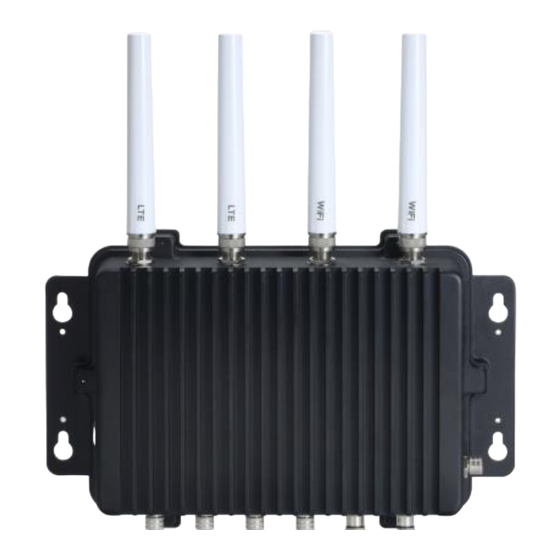
Page 26: Installation Of 3G/4G Mini Pcie Module (Full-Size)
Series user’s Manual 2.5 Installation of 3G/4G Mini PCIe Module (full-size) Step 1 Turn off the system and unplug the power cord. Step 2 Turn the system upside down to locate screws at the bottom, and then loosen all screws. - Page 27 Series user’s Manual Step 4 Connect SMA cable to I-PEX connector of 3G/4G Module and install Antenna 1 and Antenna 2. Hardware Installation...
- Page 28 Series user’s Manual This page is intentionally left blank. Hardware Installation...
-
Page 29: Section 3 Jumper & Connector Settings
Series user’s Manual SECTION 3 JUMPER & CONNECTOR SETTINGS Proper jumper settings configure the eBOX800-841-FL to meet various application needs. Hereby all jumpers settings along with their default settings are listed for devices onboard. 3.1 Locations of Jumpers & Connectors CAPA841 Top View Jumper &... - Page 30 Series user’s Manual CAPA841 Bottom View 【Note】: It is strongly recommended that any unmentioned jumper settings should not be modified without instructions by Axiomtek FAEs. Any modifications without instructions might cause system failure. Jumper & Connector Settings...
-
Page 31: Summary Of Jumper Settings
Series user’s Manual 3.2 Summary of Jumper Settings Proper jumper settings configure the eBOX800-841-FL to meet various application purposes. A table of all jumpers and their default settings is listed below. Jumpers Descriptions Settings Restore BIOS Optimal Defaults 1-2 Closed... -
Page 32: Auto Power On (Jp10)
Series user’s Manual 3.2.2 Auto Power On (JP10) If JP10 is enabled for AC power input, the system will be automatically power on without pressing soft power button. If JP10 is disabled for AC power input, it is necessary to manually... -
Page 33: Connectors
Series user’s Manual 3.3 Connectors The eBOX800-841-FL has two serial ports, COM1 and COM2 (RS-232/422/485), two Ethernets, two USBs, one VGA and one 9~36VDC connecter. Please refer to pin assignments below: 3.3.1 Serial Port (M12 A-Code 8 pos Male) -
Page 34: Usb Port (M12 A-Code 8 Pos Male)
Series user’s Manual 3.3.3 USB Port (M12 A-Code 8 pos Male) The USB is a Universal Serial Bus (compliant with USB 2.0 (480 Mbps)) connector on the rear I/O. It is commonly used for installing USB peripherals such as keyboard, mouse, scanner, etc. -
Page 35: Cfast Tm Socket (Scfast1)
Series user’s Manual 3.3.6 CFast Socket (SCFAST1) The system is equipped with a CFast socket on the bottom side to support a CFast card which is based on the SATA bus. The socket is specially designed to avoid incorrect installation of the CFast card. -
Page 36: Half-Size Pci-Express Mini Card Connector (Scn1)
Series user’s Manual 3.3.7 Half-Size PCI-Express Mini Card Connector (SCN1) The SCN1 is a half-size PCI-Express Mini Card connector. It supports the PCI-Express Mini Cards which are applied to either PCI-Express x1 or USB. It complies with PCI-Express Mini Card Spec. -
Page 37: Full-Size Pci-Express Mini Card Connector (Scn2)
Series user’s Manual 3.3.8 Full-Size PCI-Express Mini Card Connector (SCN2) This is a PCI-Express Mini Card connector on the bottom side applying to either PCI-Express or USB 2.0 or SATA (mSATA). It complies with PCI-Express Mini Card Spec.V1.2. It can also support mSATA cards. -
Page 38: Sim Card Socket (Scn3)
Series user’s Manual 3.3.9 SIM Card Socket (SCN3) This board has SCN3 socket on the bottom side for inserting SIM Card. In order to work properly, the SIM card must be used together with 3G module which is inserted to SCN1 or SCN2. -
Page 39: Waterproof Cables
Series user’s Manual 3.3.10 Waterproof Cables The eBOX800-841-FL series uses specific M12 connector for waterproof as enclosed in the accessory box; included in the box are also VGA, USB, LAN and Power cables. Please refer to pictures below for cables pin definitions. - Page 40 Series user’s Manual USB Cable With two extended USB ports, the USB cable is combined with M12 connectors for waterproof. VGA Cable Jumper & Connector Settings...
-
Page 41: Section 4 Bios Setup Utility
Series user’s Manual SECTION 4 BIOS SETUP UTILITY This section provides users with detailed descriptions in terms of how to set up basic system configurations through the BIOS setup utility. 4.1 Starting To enter the setup screens, follow the steps below: Turn on the computer and press the <Del>... -
Page 42: Main Menu
Series user’s Manual 4.3 Main Menu The Main Menu screen is the first screen users see when entering the setup utility. Users can always return to the Main setup screen by selecting the Main tab. System Time/Date can be set up as described below. -
Page 43: Advanced Menu
Series user’s Manual 4.4 Advanced Menu The Advanced menu also allows users to set configuration of the CPU and other system devices. Users can select any items in the left frame of the screen to go to sub menus: ►... - Page 44 Series user’s Manual ACPI Settings Use this screen to select options for the ACPI configuration, and change the value of the selected option. A description of the selected item appears on the right side of the screen. ACPI Sleep State When the sleep button is pressed, the system will be in the ACPI sleep state.
- Page 45 Series user’s Manual NCT6106D Super IO Monitor Use this screen to select options for the Super IO Configurations, and change the value of the selected option. A description of the selected item appears on the right side of the screen.
- Page 46 Series user’s Manual Serial Port 1 (COM1) Serial Port Enable or disable serial port 1. The optimal setting for base I/O address is 3F8h and for Interrupt request address is IRQ4. COM Port Type Use this option to set RS-232/RS-422/RS-485 mode.
- Page 47 Series user’s Manual NCT6106D HW Monitor This screen displays the temperature of system and CPU, system voltages (VCORE, +3.3V, +12V and +5V). BIOS Setup Utility...
- Page 48 Series user’s Manual CPU Configurations This screen shows the CPU information. Socket 0 CPU Information This item is for socket specific CPU information. Intel Virtualization Technology It allows a hardware platform to run multiple operating systems separately and simultaneously, enabling one system to virtually function as several systems.
- Page 49 Series user’s Manual IDE Configurations This screen shows the IDE configurations. Serial-ATA (SATA) Enable or disable the SATA Controller features. The default is Enabled. SATA Mode Selection Determine how SATA controller(s) operates. Operation mode options are IDE Mode and AHCI (Advanced Host Controller Interface) Mode;...
- Page 50 Series user’s Manual Serial-ATA Port 1 Enable or disable the onboard SATA port 1. SATA Switch This option appears only after SATA port 1 is enabled. The default is CFast If users intend to insert mSATA card to SCN2, please change setting to mSATA.
- Page 51 Series user’s Manual Trusted Computing This scree specifies TPM settings. Security Device Support Enable or disable BIOS support for security device. The default setting is Disabled. Current Status Information Display current TPM status information. BIOS Setup Utility...
- Page 52 Series user’s Manual USB Configurations USB Devices Display all detected USB devices. Legacy USB Support Use this item to enable or disable support for USB device on legacy operating system. The default setting is Enabled. Auto option disables legacy support if no USB devices are connected, Disable option will keep USB devices available o nly for EFI applications.
-
Page 53: Chipset Menu
Series user’s Manual 4.5 Chipset Menu The Chipset menu allows users to change the advanced chipset settings. Users can select any of the items in the left frame of the screen to go to the sub menus: ► North Bridge ►... - Page 54 Series user’s Manual North Bridge This screen shows memory information. For items marked with “”, please press <Enter> for more options. BIOS Setup Utility...
- Page 55 Series user’s Manual South Bridge This screen allows users to configure parameters of South Bridge chipset. Audio Controller Control detection of any Azalia device. Disabled - Azalia will be unconditionally disabled. Enabled - Azalia will be unconditionally enabled. BIOS Setup Utility...
- Page 56 Series user’s Manual Security Menu Administrator Password This item indicates whether an administrator password has been set (installed or uninstalled). User Password This item indicates whether a user password has been set (installed or uninstalled). BIOS Setup Utility...
-
Page 57: Boot Menu
Series user’s Manual 4.6 Boot Menu The Boot menu allows users to change boot options of the system. Setup Prompt Timeout Use this item to set up number of seconds to wait for setup activation key where 65535(0xFFFF) means indefinite waiting. -
Page 58: Save & Exit Menu
Series user’s Manual 4.7 Save & Exit Menu The Save & Exit menu allows users to load system configurations with optimal or fail-safe default values. Save Changes and Exit When users have completed the system configuration changes, select this option to leave Setup and return to Main Menu. - Page 59 Series user’s Manual Save Changes When completed the system configuration changes, select this option to save changes. Select Save Changes from the Save & Exit menu and press <Enter>. Select Yes to save changes. Discard Changes Select this option to quit Setup without making any permanent changes to the system configurations.
- Page 60 Series user’s Manual This page is intentionally left blank. BIOS Setup Utility...
-
Page 61: Appendix Awatchdog Timer
Series user’s Manual APPENDIX A WATCHDOG TIMER About Watchdog Timer Software stability is major issue in most applications. Some embedded systems are not watched by human for 24 hours. It is usually too slow to wait for someone to reboot when computer hangs. -
Page 62: Sample Program
Series user’s Manual Sample Program The following example enables configurations using debug tool. Enable WDT Enable configuration: O 2E 87; Un-lock super I/O O 2E 87 Select logic device: O 2E 07 O 2F 08 WDT device enable:...
Need help?
Do you have a question about the EBOX800-841-FL Series and is the answer not in the manual?
Questions and answers