
Related Manuals for ITRON SHARPFLOW SWB7


Summary of Contents for ITRON SHARPFLOW SWB7
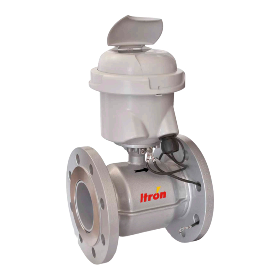
- Page 1 SHARPFLOW SWB7 + CWB7 SHARPFLOW SWB7 + CWB7 SHARPFLOW SWB7 + CWB7 SHARPFLOW SWB7 + CWB7 Quick Start Quick Start Quick Start Quick Start Battery powered electromagnetic water meter...
-
Page 2: Table Of Contents
CONTENTS SHARPFLOW SWB7 + CWB7 1 Safety instructions 1.1 Instruction for transportation and handling of batteries..........5 2 Installation 2.1 Scope of delivery....................... 6 2.2 Device description ......................7 2.3 Nameplate ........................8 2.4 Storage ..........................9 2.5 Transport .......................... 9 2.6 Pre-installation requirements .................. - Page 3 CONTENTS SHARPFLOW SWB7 + CWB7 5 Technical data 5.1 Dimensions and weights ....................29 6 Notes WA-0092.0-EN-qs-06.13 www.itron.com...
-
Page 4: Safety Instructions
SAFETY INSTRUCTIONS SHARPFLOW SWB7 + CWB7 Warnings and symbols used DANGER! This information refers to the immediate danger when working with electricity. DANGER! These warnings must be observed without fail. Even partial disregard of this warning can lead to serious health problems and even death. There is also the risk of seriously damaging the device or parts of the operator's plant. -
Page 5: Instruction For Transportation And Handling Of Batteries
SAFETY INSTRUCTIONS SHARPFLOW SWB7 + CWB7 1.1 Instruction for transportation and handling of batteries WARNING! Lithium batteries are primary power sources with high energy content. If mistreated, they may present a potential risk. INFORMATION! The manufacturer assumes no liability for customer failure. -
Page 6: Installation
INSTALLATION SHARPFLOW SWB7 + CWB7 2.1 Scope of delivery INFORMATION! Do a check of the packing list to make sure that you have all the elements given in the order. INFORMATION! Inspect the cartons carefully for damages or signs of rough handling. Report damage to the carrier and to the local office of the manufacturer. -
Page 7: Device Description
INSTALLATION SHARPFLOW SWB7 + CWB7 2.2 Device description Your measuring device is supplied ready for operation. The factory settings for the operating data have been made in accordance with your order specifications. The following versions are available: • Compact version (the signal converter is mounted directly on the measuring sensor) in polycarbonate (IP68) housing •... -
Page 8: Nameplate
INSTALLATION SHARPFLOW SWB7 + CWB7 2.3 Nameplate INFORMATION! Check the device nameplate to ensure that the device is delivered according to your order. Figure 2-3: Example of nameplate 1 Manufacturer 2 Voltage information 3 Electronic Revision number 4 Meter constant, diameter, wetted materials, protection class... -
Page 9: Storage
INSTALLATION SHARPFLOW SWB7 + CWB7 2.4 Storage • Store the device in a dry and dust-free location. • Avoid lasting direct exposure to the sun. • Store the device in its original packaging. • Storage temperature: -50 ...+70°C / -58...+158°F 2.5 Transport... -
Page 10: General Requirements
INSTALLATION SHARPFLOW SWB7 + CWB7 2.7 General requirements INFORMATION! The following precautions must be taken to ensure reliable installation. Make sure that there is adequate space to the sides. • Protect the signal converter from direct sunlight and install a sun shade if necessary. -
Page 11: Installation Conditions
INSTALLATION SHARPFLOW SWB7 + CWB7 2.8 Installation conditions 2.8.1 Inlet and outlet DN25...300 Figure 2-7: Minimal inlet and outlet 1 Inlet: ≥ 0 DN 2 Outlet: ≥ 0 DN DN350...600 Figure 2-8: Minimal inlet and outlet 1 Inlet: ≥ 3 DN 2 Outlet: ≥... -
Page 12: Bends
INSTALLATION SHARPFLOW SWB7 + CWB7 2.8.3 Bends Figure 2-10: Installation in bending pipes Figure 2-11: Installation in bending pipes CAUTION! Avoid draining or partial filling of the flow sensor 2.8.4 Open discharge Figure 2-12: Installation in front of an open discharge www.itron.com... -
Page 13: Pump
INSTALLATION SHARPFLOW SWB7 + CWB7 2.8.5 Pump Figure 2-13: Recommended installation: behind a pump 1 Inlet: ≥ 3 DN 2.8.6 Control valve Figure 2-14: Recommended installation: in front of a control valve 2.8.7 Air venting and vacuum forces Figure 2-15: Air venting 1 ≥... -
Page 14: Mounting Position And Flange Deviation
INSTALLATION SHARPFLOW SWB7 + CWB7 Figure 2-16: Vacuum 1 ≥ 5 m 2.8.8 Mounting position and flange deviation Figure 2-17: Mounting position and flange deviation • Mount flow sensor either with signal converter aligned upwards or downwards. • Install flow sensor in line with the pipe axis. -
Page 15: Ip68
INSTALLATION SHARPFLOW SWB7 + CWB7 2.8.9 IP68 The SharpFlow flow sensor is rated IP68 (NEMA 4X/6P). It is suitable for submersion in flooded measurement chambers and for subsurface installation. The compact SharpFlow CWB7 signal converter is available in: • a polycarbonate housing suitable for IP68, NEMA 4/4X/6. -
Page 16: Mounting
INSTALLATION SHARPFLOW SWB7 + CWB7 2.9 Mounting 2.9.1 Torques and pressures The maximum pressure and torques values for the flowmeter are theoretical and calculated for optimum conditions and use with carbon steel flanges. Figure 2-19: Tightening of bolts • Always tighten the bolts uniformely and in diagonally opposite sequence. - Page 17 INSTALLATION SHARPFLOW SWB7 + CWB7 Nominal size Pressure Bolts Max. torque DN [mm] rating [Nm] PN 16 4 x M 12 PN 16 4 × M 16 PN 16 4 × M 16 PN 16 8 × M 16 PN 16 8 ×...
- Page 18 INSTALLATION SHARPFLOW SWB7 + CWB7 Nominal size Flange class Bolts Max. torque [inches] [lb] [lbs.ft] 4 x 1/2" 1½ 4 x 1/2" 4 × 5/8" 8 x 5/8" 4 × 5/8" 8 × 5/8" 8 × 3/4" 8 × 3/4"...
-
Page 19: Mounting Of The Signal Converter
INSTALLATION SHARPFLOW SWB7 + CWB7 2.10 Mounting of the signal converter INFORMATION! Assembly materials and tools are not part of the delivery. Use the assembly materials and tools in compliance with the applicable occupational health and safety directives. 2.10.1 IP67 housing, remote version... -
Page 20: Electrical Connections
ELECTRICAL CONNECTIONS SHARPFLOW SWB7 + CWB7 3.1 Safety instructions DANGER! All work on the electrical connections may only be carried out with the power disconnected. Take note of the voltage data on the nameplate! DANGER! Observe the national regulations for electrical installations! WARNING! Observe without fail the local occupational health and safety regulations. -
Page 21: Connection Of The Signal Cable
ELECTRICAL CONNECTIONS SHARPFLOW SWB7 + CWB7 3.3 Connection of the signal cable 3.3.1 IP 67 housing (field version) CAUTION! To ensure smooth functioning, always use the signal cables included in the delivery. INFORMATION! The signal cable is only used for remote versions. The standard WSC-cable includes both electrode and field current leads. - Page 22 ELECTRICAL CONNECTIONS SHARPFLOW SWB7 + CWB7 Figure 3-4: Cable connection at converter side, standard cable 1 Connect drain wires under screw 2 Connect shielding under clamp • Prepare appropriate cable lengths as shown. • Connect the wires as shown in the following table.
-
Page 23: Connection Of The Output Cable
ELECTRICAL CONNECTIONS SHARPFLOW SWB7 + CWB7 3.4 Connection of the output cable 3.4.1 IP67 housing (field version) Figure 3-5: Removing side cap Figure 3-6: Terminal assignment Electrical values • Pulse output passive: Pulse output passive: Pulse output passive: Pulse output passive: f ≤... - Page 24 ELECTRICAL CONNECTIONS SHARPFLOW SWB7 + CWB7 Meter size / pulse weight table Diameter liters/pulse 1000 1000 www.itron.com WA-0092.0-EN-qs-06.13...
-
Page 25: Ip68 Housing (Compact Version)
ELECTRICAL CONNECTIONS SHARPFLOW SWB7 + CWB7 3.4.2 IP68 housing (compact version) Figure 3-7: Output cable at IP68 compact version 1 Color coded leads of output cable Output cable with IP68 rated connectors with 5 color coded leads: Wire color Function... -
Page 26: Start-Up
START-UP SHARPFLOW SWB7 + CWB7 4.1 Connecting the internal battery CAUTION! Please connect the battery before first use. The signal converter is delivered with a disconnected battery. In case the meter is verified to MI-001, the batteries are already connected in the factory. -
Page 27: Connecting The External Battery
START-UP SHARPFLOW SWB7 + CWB7 4.2 Connecting the external battery 4.2.1 IP67 housing (compact and field version) • Remove the protection cap and loosen the 4 Allen bolts (4mm). • Remove the cover. • Remove one of the blind cable glands in the bottom of the converter housing. -
Page 28: Battery
START-UP SHARPFLOW SWB7 + CWB7 4.2.3 Battery After a change of battery: • Reset the bettery lifetime counter (Menu number B2) • Select the battery type, if a different type of battery is used. (Menu number B0) • Change the total battery capacity, if a different type of battery is used. (Menu number B1) - Page 29 TECHNICAL DATA SHARPFLOW SWB7 + CWB7 5.1 Dimensions and weights Remote flow sensor Remote flow sensor a = 88 mm / 3.5" Remote flow sensor Remote flow sensor b = 139 mm / 5.5" c = 106 mm / 4.2"...
- Page 30 TECHNICAL DATA SHARPFLOW SWB7 + CWB7 EN 1092-1 Nominal size Dimensions [mm] Approx. weight DN [mm] [kg] ASME B16.5 / 150 lb Nominal size Dimensions [inches] Approx. weight [inches] [lb] 5.91 5.83 1½ 5.91 7.87 7.05 7.87 8.03 9.84 9.49 9.84...
- Page 31 NOTES SHARPFLOW SWB7 + CWB7 WA-0092.0-EN-qs-06.13 www.itron.com...
- Page 32 67500 Haguenau - France Phone: +33 3 88 90 63 00 WA-0092.0-EN-qs-06.13 WA-0092.0-EN-qs-06.13 WA-0092.0-EN-qs-06.13 WA-0092.0-EN-qs-06.13 Fax: +33 3 88 73 23 20 www.itron.com © Copyright 2011, Itron. All Rights Reserved. - Itron reserves the right to change these specifications without prior notice.
Need help?
Do you have a question about the SHARPFLOW SWB7 and is the answer not in the manual?
Questions and answers