
Related Manuals for ITRON Intelis Gas Meter


Summary of Contents for ITRON Intelis Gas Meter
- Page 1 Intelis Gas Meter Installation Guide knowledge to shape your future INSTALLATION GUIDE...
- Page 2 All other product names and logos in this documentation are used for identification purposes only and may be trademarks or registered trademarks of their respective companies. For more information about Itron or Itron products, go to www.itron.com. If you have questions or comments about a software or hardware product, contact Itron Technical Support Services. Contact Email: support@itron.com...
-
Page 3: Table Of Contents
Electromagnetic Compatibility Intrinsic Safety Lithium Battery Transportation Classification Electrostatic Discharge Electrostatic Ignition Hazard Device Cleaning Do Not Drop Product Notification Intelis Gas Meter Related Documents Models Components Internal Safety Shutoff Valve Integrated RF Communications Module Specifications Dimensions Installation Prior to Start-Up... - Page 4 Proving the Intelis Gas Meter Using the Honeywell SNAP Proving System Proving the Intelis Gas Meter Using the Measurement Systems Proving System Proving the Intelis Gas Meter Using the Energy Economics (EEI) Proving System Adjusting the Calibration To Adjust the Calibration of an Intelis Gas Meter...
-
Page 5: Important Safety And Compliance Information
To ensure system performance, this device and antenna shall not be changed or modified without the express approval of Itron. Per FCC rules, unapproved modifications or operation bey- ond or in conflict with these instructions for use could void the user's authority to operate the equipment. -
Page 6: Canada, Ised Spectrum Compliance
Intelis Gas Meter Installation Guide 1 Important Safety and Compliance Information Canada, ISED Spectrum Compliance Compliance Statement Canada Déclaration de Conformité This device complies with Innovation, Science Le présent appareil est conforme aux CNR and Economic Development Canada (ISED) d'Industrie Canada applicables aux appareils license-exempt RSS standard(s). -
Page 7: Electromagnetic Compatibility
The Federal Aviation Administration prohibits operating transmitters and receivers on all com- mercial aircraft. When powered and not in Factory ship mode, the Itron device is considered an operating transmitter and receiver and cannot be shipped by air. All product returns must be shipped by ground transportation. -
Page 8: Electrostatic Ignition Hazard
RF -40° F (-40° C) to +158° F (70° C) ■ Storage range: – -40° F (-40° C) to +158° F (70° C) ■ Direct inquiries as to the selection and application of gas meters to your local Itron sales rep- resentative or Itron Support. 11 December 2019 TDC-1782-005... - Page 9 Intelis Gas Meter Installation Guide 1 Important Safety and Compliance Information ■ Itron does not endorse or warrant the completeness or accuracy of any third-party meter installation procedures or practices, unless otherwise provided in writing by Itron. – Follow your company's standard operating procedures regarding the use of personal pro- tection equipment (PPE).
-
Page 10: Intelis Gas Meter
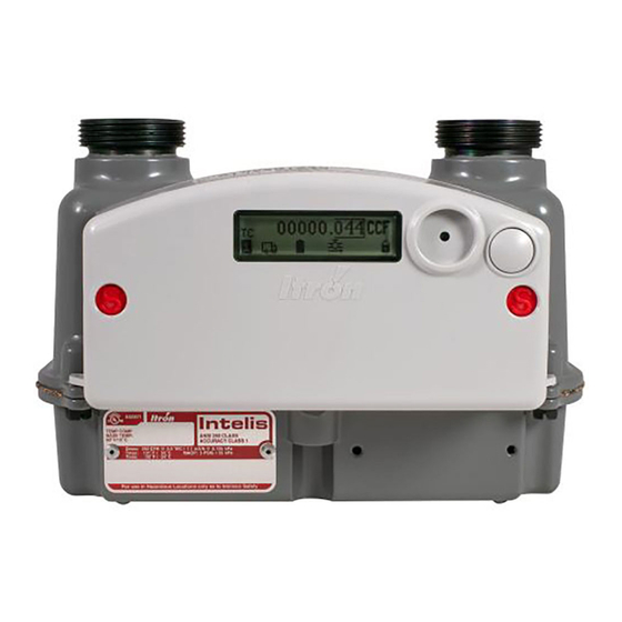
I ntelis Gas Meter The Intelis Gas Meter is a solid state ultrasonic meter featuring an internal safety shut-off valve, built-in temperature conversion, and an integrated RF communications module. The meter sup- ports the listed functionality. ■ High flow alarm with optional automatic valve shutoff. -
Page 11: Models
■ Temperature compensated ■ Non-temperature compensated Components The Intelis Gas Meter features the following components in a compact solid state meter: ■ Intelis Gas Meter index – The index contains the integrated RF communications module, battery pack, and the liquid crystal display (LCD). The LCD provides a visual display of consumption, alarm messages, and status information. -
Page 12: Internal Safety Shutoff Valve
The integrated RF communications module is designed to operate in either Mobile or OpenWay Riva Network Mode. When the Intelis Gas Meter is operating in Mobile Mode, it may be read by ChoiceConnect handheld readers, mobile collection, or the Itron Mobile Radio connected to a user-supplied computer or Bluetooth device. - Page 13 Intelis Gas Meter Installation Guide 2 Intelis Gas Meter Table 1Intelis Gas Meter specifications (continued) Specification Specification value Accuracy Class 1 and ±0.5% at room temperature Meter type Temperature compensated (TC) or non-temperature compensated (NTC) Hub center-to-center 6 inches (152.4 mm) ■...
-
Page 14: Dimensions
Itron Mobile v1.5 Mobile Collection v3.8.2 Standards Designed in compliance with ANSI B109.1, ANSIB109.0 (draft), and Measurement Canada PS-G-06 Dimensions This section lists the Intelis Gas Meter dimensions. Dimensions are listed in Imperial and Metric units. 11 December 2019 TDC-1782-005... - Page 15 Intelis Gas Meter Installation Guide 2 Intelis Gas Meter Table 2Intelis Gas Meter dimensions 8.4 inches 6.4 inches 6.0 inches 5.4 inches 3.1 inches 9.1 inches 1.9 inches 214.4 mm 161.9 mm 152.4 mm 138.3 mm 78.6 mm 230.6 mm 48.8 mm...
-
Page 16: Installation
The Intelis Gas Meter must be installed with the inlet to the left, the outlet to the right, the meter in a horizontal position and with the LCD facing out. INLET and a flow arrow are marked on the Intelis Gas Meter casing. -
Page 17: Prior To Start-Up
3 Installation Prior to Start-Up Note: The Intelis Gas Meter is shipped from the factory with the shutoff valve in the open pos- ition. Verify the valve is open prior to installing the meter. Confirm the open valve icon is dis- played on the LCD display and that the valve closed icon is not displaying. -
Page 18: Removing Or Installing The Pipe Plug
If necessary, change out the meter. 10. Perform a shadow or lock-in test following company or utility procedures. 11. After the Intelis Gas Meter installation testing is complete, purge all air from the gas line including the piping section. - Page 19 Intelis Gas Meter Installation Guide 3 Installation 2. Apply new sealant to the leading 3 to 4 threads of the pipe plug. Note: Itron recommends RectorSeal #5 sealant. 3. Using a 3/16" hand-driven Allen wrench, begin tightening the pipe plug into the threads, using care not to cross-thread or remove the sealant during the process.
-
Page 20: Lcd Operation
This section provides information about the Intelis Gas Meter LCD. Intelis Gas Meter LCD This section describes the Intelis Gas Meter LCD menus that are displayed in a pre-defined order (1-8). Note: The Intelis Gas Meter ships in a sealed (locked) state. - Page 21 Before the display moves to the next menu page, all active alarms are dis- played. If there are no alarms, NO ALARM displays. For more information about the Intelis Gas Meter display events and alarms, see LCD Display Alarms.
-
Page 22: Lcd Display Alarms
Unit CRC LCD Display Alarms The Intelis Gas Meter reports the following alarms on the LCD regardless of the programming mode. When the meter is programmed to Network Mode, events are logged with a start time (see the following information for alarms that also have an end time). Users may cross check alarms over the network or with a device loaded with FDM Tools. - Page 23 Intelis Gas Meter Installation Guide 4 LCD Operation Warning! The automatic high flow valve closure will not operate if the meter is in an unrecoverable error state. This includes: Flow Meas. Hard fail., Flow Sens. Meas. Error, and/or Transducer Error.
- Page 24 Intelis Gas Meter Installation Guide 4 LCD Operation Table 3LCD display alarms and description (continued) LCD alarm Description Air in Pipe detect. The meter detected air in the meter. The air in pipe alarm will be set to ‘ready to detect’...
-
Page 25: Additional Lcd Screen Displays
Flow Sens. Meas. Error The meter detected that a flow sensor measurement error occurred. This is an unrecoverable error. Remove the meter and return it to Itron for evaluation. This alarm has a start log. Transducer Error. The meter detected that its ultrasonic transducers experienced an error. -
Page 26: Lcd Display Icons
Intelis Gas Meter Installation Guide 4 LCD Operation provides a visual confirmation that the LCD is functioning correctly. LCD Display Icons The Intelis Gas Meter LCD display provides the following menu icons as a visual indications of status information. Table 4Menu icons... -
Page 27: Performing An Lcd Test
Performing an LCD Test The Intelis Gas Meter LCD Test is used to confirm the LCD display is functioning properly and that there are no non-displaying pixels that could lead to misinterpretation of a value. -
Page 28: Proving
(PPE). Adhere to guidelines issued by your com- pany in addition to those contained in this document when proving meters. The Intelis Gas Meter Test Mode and a prover station are used to confirm the accuracy of the meter. -
Page 29: Test Mode
■ Maximum Test Mode time. Default is 1 hour. Important! The default Test Mode time is 1 hour. The Intelis Gas Meter will auto- matically time out after 1 hour in Test Mode whether there is activity or not. Test Mode configuration can be completed at the factory at the time the meter is manufactured. -
Page 30: Recording Test Mode Consumption
1. The Intelis Gas Meter records the Test Mode consumption in the Test Mode index register. 2. The Intelis Gas Meter continues to output an optical pulse. Note: While the Intelis Gas Meter is in Test Mode, the LCD refresh rate is more frequent than when the meter is operating in Normal Mode. -
Page 31: Proving The Intelis Gas Meter Using The Honeywell Snap Proving System
Itron BPG SONICAL SNG6 Proving the Intelis Gas Meter Using the Honeywell SNAP Proving System This section provides the information to set up an Intelis Gas Meter using a Honeywell SNAP proving system. Note: Proving the Intelis Gas Meter requires Honeywell SNAP prover software .NET X.Y. - Page 32 1. If you have not previously done so, log on to the prover. Note: If you are proving an Intelis Gas Meter for the first time on the prover or if you are changing proving parameters for the Intelis Gas Meter, you must log on as a Supervisor.
- Page 33 Intelis Gas Meter Installation Guide 5 Proving 2. Select Special Functions. 3. Select Edit Config Tables. 11 December 2019 TDC-1782-005...
- Page 34 4. Select Edit Setup Values. 5. Select the MeterMfg_Table checkbox. 6. Click in the next available (open) row in the top left table and enter ITRON-RTY for the meter manufacturer. Click off of the table and select Update Table. 11 December 2019...
- Page 35 Intelis Gas Meter Installation Guide 5 Proving Important! If Itron, Actaris, Sprague, or other is listed, it is still necessary to add a new manufacturer name specifically for the Intelis Gas Meter. Itron suggests using ITRON-RTY following the steps listed below. The MFR Type must have the RTY suffix to allow setting and saving the revs desired for any given test and flow rate.
- Page 36 Intelis Gas Meter Installation Guide 5 Proving 8. Update the parameters in the table. – MeterName: Intelis 250 – MeterMfg: ITRON-RTY – Open proof: 100 – Check proof: 100 – Other proof: 100 – Open flow: 250 (or the setting required by your utility) –...
- Page 37 Intelis Gas Meter Installation Guide 5 Proving 9. Verify or enter the TOLERANCE values for POS, NEG, Slope, Repair, and Meter Size. These settings (values) are utility-specific. 10. Click off the table and select Update Table. 11. Select Exit, select Exit, select Exit.
- Page 38 Intelis Gas Meter Installation Guide 5 Proving Proving the Intelis Gas Meter 1. Select Prove Meter. 2. Select the meter manufacturer (ITRON-RTY). 3. Select Intelis 250. 4. Select the correct mode for your meter (TC or NTC). Note: REG is equivalent to NTC 5.
- Page 39 Intelis Gas Meter Installation Guide 5 Proving 6. Select the test mode (intest, outtest). 7. Select the optic test method (optic, mag). 8. Select the correct Index (volume per pulse) setting (Imperial, ¼ CF; Metric, 10 dm3). 11 December 2019...
- Page 40 SNAP prover electronic enclosure, next to the meter temperature probe port. 11. Connect the Intelis Gas Meter end of the SNAP pulse prover cable to the Intelis Gas Meter optical port by firmly pressing the aluminum round threads of the cable into the port. Begin by positioning the cable at the 4:30 o'clock position.
-
Page 41: Proving The Intelis Gas Meter Using The Measurement Systems Proving System
Proving the Intelis Gas Meter Using the Measurement Systems Proving System This section provides the information to set up an Intelis Gas Meter using a Measurement Sys- tems proving system. Note: Proving the Intelis Gas Meter requires Measurement Systems prover software. See the Measurement Systems prover documentation for version requirements. - Page 42 Intelis Gas Meter Installation Guide 5 Proving Itron recommends these Intelis Gas Meter Test Mode parameter settings for the Measurement Systems proving system: ■ Test Mode pulse weight: 0.25 CF ■ Test Mode pulse width: 150 ms Temper the Meter by Exercising the Meter 1.
- Page 43 4. From the Operate Valves and Observe Sensor Readings screen, press the 1 key or Chuck Valve to clamp the meter in place. 5. After the Intelis Gas Meter is clamped to the prover, turn on the appropriate nozzle in the cen- ter of the screen to exercise the meter.
- Page 44 Intelis Gas Meter Installation Guide 5 Proving Exercise the meter for 10 to 15 minutes before proving the meter. 6. Close the nozzle. 7. Unclamp the meter by pressing the Chuck Valve button. 8. Exit Operate Valves and Observe Sensor Readings.
- Page 45 Intelis Gas Meter Installation Guide 5 Proving 3. Select the Meter Model-1 tab. 4. Select the meter model. If the Intelis 250 or Intelis 250 TC are set up in the MMS prover, go to step 10. If the Intelis 250 or Intelis 250 TC is not listed, continue to step 5.
- Page 46 6. Select Enter New Meter Model. 7. Select an existing meter model similar to the new meter as a template. Itron recommends using the S-250 for an Intelis 250 gas meter and an S-250 TC for the Intelis 250 TC gas meter.
- Page 47 9. Press Enter or click the blue bar at the bottom of the screen to go back to the meter setup menu. 10. Select the Exercise Cycle Duration. The Intelis Gas Meter Exercise Cycle Duration is typ- ically 15 seconds.
- Page 48 Intelis Gas Meter Installation Guide 5 Proving 11. Set Leak Test to Yes. 12. Verify or enter Test Revs: Index Open, Check, Other settings. Itron recommended settings are listed. – Open: 6 – Check: 2 11 December 2019 TDC-1782-005...
- Page 49 13. Select the Volume: Index setting. The Volume: Index setting is the recommended volume per pulse. Itron recommended settings are listed. – Imperial setting: 0.25 cu ft/rev – Metric setting: 0.01 m3/rev Note: Intelis Gas Meter volume per pulse is in dm3; 10dm3 = 0.01 m3. 11 December 2019 TDC-1782-005...
- Page 50 Intelis Gas Meter Installation Guide 5 Proving 14. Verify or enter Flow rates (Air Rate): Open, Check, Other settings. Itron recommended typ- ical settings are listed. For metric flow rates: choose from the flow rate dropdown list options. These convert the Imperial (CFH) flow rates to Metric (CMH). The Other flow rate is not required if the Test Revs: Index-Other is set to 0.
- Page 51 Intelis Gas Meter Installation Guide 5 Proving Important! Required Open and Check flow rates may be different than those shown here. 15. Select the Proving Method: Index. The options are Index or Magnetic. 16. Select the mode for your meter. Available options are TC or NON-TC.
- Page 52 Intelis Gas Meter Installation Guide 5 Proving 17. Select the Meter Model-2 tab. 18. Verify or enter the InTest and OutTest limit values for Open Limits, Check Limits, Other Lim- its, and Delta Limit. The Open, Check, Other, and Delta Limit settings (values) are utility-spe- cific.
- Page 53 Note: The Tangent Adjustment: Tangent Type setting can be any non-blank value. The Tangent Adjustment: Tangent Type value is not used to prove the Intelis Gas Meter. 21. Select the Global tab and Display Method for your meter results. Display Method options are listed.
- Page 54 Intelis Gas Meter Installation Guide 5 Proving – Error – Accuracy – Proof 22. Select InTest/OutTest. The options are InTest or OutTest. 11 December 2019 TDC-1782-005...
- Page 55 23. Press or click the green bar at the bottom of the screen to exit the Meter Setup Menu. Proving the Intelis Gas Meter 1. Connect the Measurement Systems pulse prover cable (Itron part number CFG-7100-500) to the port on the left side of the Measurement Systems prover.
- Page 56 Intelis Gas Meter Installation Guide 5 Proving 2. Connect the Intelis Gas Meter end of the Measurement Systems pulse prover cable to the Intelis Gas Meter by firmly pressing the aluminum round threads of the cable into the port. Begin by positioning the cable at the 4:30 o'clock position. Tighten the cable to the 6:30 o'clock position.
- Page 57 Intelis Gas Meter Installation Guide 5 Proving 3. Enter the Intelis Gas Meter serial number. 4. Press or click the green bar on the bottom of the screen to begin the Measurement Systems proving test. 5. Verify the LED blinks (pulses) when the air begins to flow through the meter.
-
Page 58: Proving The Intelis Gas Meter Using The Energy Economics (Eei) Proving System
Proving the Intelis Gas Meter Using the Energy Economics (EEI) Proving System This section provides the information to set up an Intelis Gas Meter using an EEI proving system. Note: Proving the Intelis Gas Meter requires Energy Economics prover software. - Page 59 5 Proving 2. Select Maintain > Sensor Maintenance. 3. Clamp the Intelis Gas Meter to the prover and turn on appropriate nozzles in the center column of the Sensor Maintenance window to exercise the meter. Note: Nozzle 192 CFH is typically used to exercise the Intelis Gas Meter.
- Page 60 Important! If ITRON is not in the Manuf. drop-down list, contact EEI Prover Sys- tems for help in adding ITRON to your EEI Systems Prover. 4. Select Intelis 250, Intelis 250 TC, or the name for the Intelis Gas Meter designated by your company from the Type drop-down list.
- Page 61 Intelis Gas Meter Installation Guide 5 Proving The Meter Information > Test Options window opens. 6. Select Eye for the Test Options Sensor. 11 December 2019 TDC-1782-005...
- Page 62 Intelis Gas Meter Installation Guide 5 Proving 7. Select Open & Check for the Run Type Test Options. 11 December 2019 TDC-1782-005...
- Page 63 Intelis Gas Meter Installation Guide 5 Proving 8. Enter 100 for Flow > Open %. Important! Required Open flow rates may be different than those shown here. 11 December 2019 TDC-1782-005...
- Page 64 Intelis Gas Meter Installation Guide 5 Proving 9. Enter 20 for Flow > Check %. Important! Required Check flow rates may be different than those shown here. 11 December 2019 TDC-1782-005...
- Page 65 Intelis Gas Meter Installation Guide 5 Proving 10. Select 1/10 cuft for Hand Size. 11. Click Done to complete the Meter Information > Test Options and close the window. 11 December 2019 TDC-1782-005...
- Page 66 1. Connect the EEI pulse prover cable (Itron part number CFG-7100-400) to the EEI prover index eye connector. 2. Connect the Intelis Gas Meter end of the EEI pulse prover cable to the Intelis Gas Meter by firmly pressing the aluminum round threads of the cable into the port. Begin by positioning the cable at the 4:30 o'clock position.
-
Page 67: Adjusting The Calibration
Intelis Gas Meters are calibrated at the factory prior to shipment. FDM is used if it is necessary to recalibrate the meter. For more information about calibrating the Intelis Gas Meter using FDM, see the FDM Field Service Representatives Guide. For documentation information, see Related Documents. - Page 68 Intelis Gas Meter Installation Guide 6 Adjusting the Calibration 4. Select Yes. 5. (Mobile ChoiceConnect mode only) If you are prompted to enter the Unlock ID, enter the Unlock ID. 11 December 2019 TDC-1782-005...
- Page 69 Intelis Gas Meter Installation Guide 6 Adjusting the Calibration 6. Select Next. The Parameter screen appears. 11 December 2019 TDC-1782-005...
- Page 70 Intelis Gas Meter Installation Guide 6 Adjusting the Calibration To demonstrate an example of adjusting the calibration, a sample prover station test result is displayed below for reference. Note: Depending on the meter's firmware version, FDM may accept flow rate entries only in a whole number format or it may accept flow rate entries of up to two decimal places.
- Page 71 Intelis Gas Meter Installation Guide 6 Adjusting the Calibration – (Example selection) % Error – % Accuracy – % Proof Prover flow rate unit. From the drop-down menu, select the flow rate unit: – (Example selection) Imperial (cubic feet per hour) –...
- Page 72 Intelis Gas Meter Installation Guide 6 Adjusting the Calibration 8. Select Next. A progress bar indicates that the meter's calibration is being adjusted. 11 December 2019 TDC-1782-005...
- Page 73 Intelis Gas Meter Installation Guide 6 Adjusting the Calibration The meter uses the entered values to calculate the required calibration parameters to a tar- get of one of the following, depending on your selected prover station mode: – % Error. 0% open, 0% check –...
-
Page 74: To Seal An Intelis Gas Meter
If the accuracy results are not as expected, repeat the calibration steps. Note: Prover station accuracy is estimated to be +/- 0.15-0.25%. To Seal an Intelis Gas Meter 1. From the Tools menu, select Intelis Gas Meter. 2. Select Test Mode Operations. 11 December 2019... - Page 75 Intelis Gas Meter Installation Guide 6 Adjusting the Calibration 3. Select Seal Meter. A progress bar indicates that the meter is sealing. The Seal Meter Operation Successful screen indicates that the meter is sealed. 11 December 2019 TDC-1782-005...
-
Page 76: To Unseal An Intelis Gas Meter's Umu
Intelis Gas Meter Installation Guide 6 Adjusting the Calibration 4. Select Finish to return to the Tools screen. To Unseal an Intelis gas Meter's UMU 1. From the Tools menu, select OWR Intelis Gas Riva. 2. Enter the Endpoint ID. - Page 77 Intelis Gas Meter Installation Guide 6 Adjusting the Calibration 10. (Moblie endpoint mode only) Enter the Unlock ID. 11. Select Next. The Adjust Calibration screen appears. 12. Click Quit or Finish to return to the Tools screen. 11 December 2019...
-
Page 78: Maintenance
M aintenance The Intelis Gas Meter is designed to be maintenance free, however; the LCD index as well as the meter batteries are replaceable. If the LCD is damaged or requires replacement, see the Intrinsic Safety Control Drawing for Index Module Replacement of Itron Model Intelis Gas Meter (TDC-0978-009) instructions.
Need help?
Do you have a question about the Intelis Gas Meter and is the answer not in the manual?
Questions and answers