Sign In
Upload
Download
Table of Contents
Contents
Add to my manuals
Delete from my manuals
Share
URL of this page:
HTML Link:
Bookmark this page
Add
Manual will be automatically added to "My Manuals"
Print this page
×
Bookmark added
×
Added to my manuals
Manuals
Brands
ITRON Manuals
Measuring Instruments
SL7000
User manual
ITRON SL7000 User Manual
Hide thumbs
1
2
Table Of Contents
3
4
5
6
7
8
9
10
11
12
13
14
15
16
17
18
19
20
21
22
23
24
25
26
27
28
29
30
31
32
33
34
35
36
37
38
39
40
41
42
43
44
45
46
47
48
49
50
51
52
53
54
55
56
57
58
59
60
61
62
63
64
65
66
67
68
69
70
71
72
73
74
75
76
77
78
79
80
81
82
83
84
85
86
87
88
89
90
91
92
93
94
95
96
97
98
99
100
101
102
103
104
105
106
107
108
109
110
111
112
113
114
115
116
117
118
119
120
121
122
123
124
125
page
of
125
Go
/
125
Contents
Table of Contents
Bookmarks
Table of Contents
Table of Contents
1 About this Guide
Audience
Scope
Abbreviations
2 Certification
Applicable Standards
CE Certificates of Conformity
Sl761W
SL761X and SL761Y
End-Of-Life Disposal
3 Safety Information
4 General Information
Meter Overview
General Specifications
Meter Support Tools
Configuration Options
Meter Identification
Meter Product Coding
Meter Markings
Terminal Numbering
5 Technical Specification
6 Technical Description
Metrology
External Connections (I/Os)
Control Input
Control Output
Pulse Input
Pulse Output
Metrology LED Indicators
Power Supplies
Power-Fail Operation
Real-Time Clock
Calendar
Energy Rate Switching
Daylight Saving
Seasons
Week Profiles
Day Profiles
Indexes
Index Activation
Special Days
Backup Power Supply
Metered Quantities
Four Quadrant Metering
Measured Energy Quantities
Summation Energy
Instantaneous Energy Quantities
Primary and Secondary Data for CT and CT/VT Meters
Total Energy Registers (TER)
Energy Registering
Energy Channels
Energy Rate Registers
Summation Registers
Demand Registering
Demand Channels
Demand Registers
Integration Period
Demand Calculation
End of Integration (EOI)
Excess Demand Modes
Load Profiles
Excess Energy
Meter Billing
Billing Periods
End of Billing (EOB) Event
Historical Buffer Registers
Network Quality Monitoring
Monitoring
Fraud Protection Measures
Magnetic Field Detection
Alarm and Event Management
Logbook
Event Histories
Alarm Type and Classification
Alarm Notification
Remote Firmware Upgrade
UFER/DMCR and ABNT Protocol
Ufer/Dmcr
ABNT Protocol
7 Communications
Optical Interface
Serial Data Ports
Real-Time Data
Modem Connection
Communication Management
DL\T645-2007 Protocol
8 Meter Displays
Displays and Annunciators
Meter Pushbuttons
Meter Display Modes
9 Installation
Warnings
Environmental
Dimensions
Fixings
Auxiliary and Communication Wiring
Using Aluminium Cables
Cabling
Three-Phase LV CT Connections
Wire Asymmetrical (VDE) Current Transformer Configuration
Wire Asymmetrical (VDE) Current Transformer Configuration
Wire Symmetrical (USE) Current Transformer Configuration
Wire Symmetrical (USE) Current Transformer Configuration
Three-Phase HV CT Connections
4-Wire 3 X VT and 3 X CT
3-Wire 2 X VT and 2 X CT
3-Wire 3 X VT and 2 X CT
3-Wire 2 X VT and 3 X CT
3-Wire ARON Connection
Direct Connected: 4-Wire Asymmetrical (VDE) Direct Connection Configuration
Battery
Installation Checks
Start-Up and Functional Checks
Sealing the Meter
10 Technical Appendix
Logbook Contents
Alarms
Alarms Description
LCD Code Correspondence with Alarm
MID Display List
Advertisement
Quick Links
1
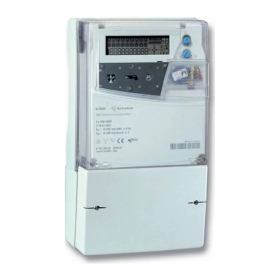
Meter Overview
Download this manual
SL7000 IEC7
User Guide
Table of
Contents
Previous
Page
Next
Page
1
2
3
4
5
Advertisement
Table of Contents
Need help?
Do you have a question about the SL7000 and is the answer not in the manual?
Ask a question
Questions and answers
Related Manuals for ITRON SL7000
Measuring Instruments ITRON SL7000 IEC7 User Manual
(99 pages)
Measuring Instruments ITRON SHARPFLOW SWB7 Quick Start Manual
Battery powered electromagnetic water meter (32 pages)
Measuring Instruments ITRON SL761X User Manual
(125 pages)
Measuring Instruments ITRON 100W Installation Manual
Pit datalogging water endpoint (20 pages)
Measuring Instruments ITRON CENTRON C1SR Technical Reference Manual
(107 pages)
Measuring Instruments Itron Centron Technical Reference Manual
(100 pages)
Measuring Instruments ITRON OpenWay Intelis Installation Manual
Gas meter (19 pages)
Measuring Instruments ITRON ACE6000 User Manual
(85 pages)
Measuring Instruments ITRON CCU 100 Installation Manual
Choiceconnect (72 pages)
Measuring Instruments Itron Delta Instruction Manual
Rotary-meters (72 pages)
Measuring Instruments ITRON MC3Lite Hardware Installation Manual
Mobile meter readers (45 pages)
Measuring Instruments ITRON Axonic User Manual
(76 pages)
Measuring Instruments ITRON RF1 Instruction Manual
Diaphragm gas meter (3 pages)
Measuring Instruments ITRON EM512 TYPE 700 JV1 Technical And User Manual
(25 pages)
Measuring Instruments itron MZT Instruction Manual
Turbines gas meter (44 pages)
Measuring Instruments ITRON Delta Series Instruction Manual
Rotary-meter (68 pages)
This manual is also suitable for:
Sl761w
Sl761x
Sl761y
Table of Contents
Save PDF
Print
Rename the bookmark
Delete bookmark?
Delete from my manuals?
Login
Sign In
OR
Sign in with Facebook
Sign in with Google
Upload manual
Upload from disk
Upload from URL


Need help?
Do you have a question about the SL7000 and is the answer not in the manual?
Questions and answers