Table of Contents
Advertisement
Advertisement
Table of Contents

Subscribe to Our Youtube Channel
Related Manuals for ITRON CCU 100


Summary of Contents for ITRON CCU 100
- Page 1 ChoiceConnect CCU 100 and Repeater 100 Installation Guide...
- Page 2 All other product names and logos in this documentation are used for identification purposes only and may be trademarks or registered trademarks of their respective companies. Suggestions If you have comments or suggestions on how we may improve this documentation, send them to TechnicalCommunicationsManager@itron.com If you have questions or comments about the software or hardware product, contact Itron Technical Support: Contact Internet: www.itron.com...
-
Page 3: Table Of Contents
Lightning Arrestor ..........................12 AC Mains Power ..........................13 DC Mains Power ..........................13 Materials Not Provided by Itron ......................13 Coaxial Cable .......................... 13 Antenna Connectors ....................... 15 Mounting Hardware ......................... 15 CCU 100 and Repeater 100 Installation Guide Proprietary and Confidential... - Page 4 CCU/Repeater Power Operating Range ................... 60 Battery Pack ............................61 Appendix B Status and Diagnostics ................. 63 Status Indicator ..........................63 Performing an Antenna Sweep Test ....................64 Index ..........................65 CCU 100 and Repeater 100 Installation Guide Proprietary and Confidential...
-
Page 5: Before You Begin
Before You Begin Important Proper installation of the CCU/Repeater ensures trouble-free operation of the Itron Fixed Network system. The installation of both the collector and repeater must be done by professional installers. Documentation Conventions This document uses the following conventions. - Page 6 Before You Begin CCU 100 and Repeater 100 Installation Guide Proprietary and Confidential...
-
Page 7: Chapter 1 Ccu/Repeater Basics
H A P T E R CCU/Repeater Basics The CCU 100 (also known as a cell control unit or collector) and the Repeater 100 are configurable for different installation locations, including: • On a water or communications tower. • On a pole (such as an electricity or light pole). -
Page 8: Ccu/Repeater Components
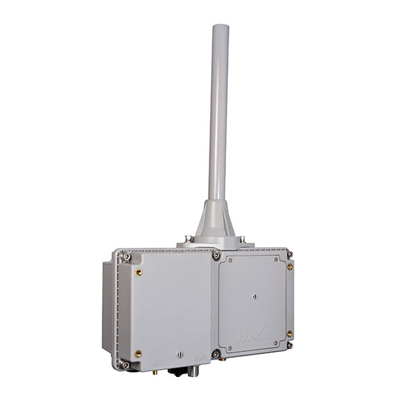
Chapter 1 CCU/Repeater Basics CCU/Repeater Components The CCU 100 and Repeater 100 come in two basic configurations; they may have either internal GPS/WAN antennas or external GPS/WAN antennas. The external CCU/Repeater configuration replaces the internal GPS/WAN antennas with external antenna connectors that allow both GPS and WAN antennas to be mounted externally. In the case of the Repeater 100, only an external GPS connection is provided;... - Page 9 This female SMA connector is only on the external antenna CCU/Repeater. Use this connector when mounting the GPS antenna externally. External WAN antenna connector This female N connector is only on the external antenna CCU. Use this connector when mounting the WAN antenna externally. CCU 100 and Repeater 100 Installation Guide Proprietary and Confidential...
-
Page 10: External Gps/Wan Antenna System
Ethernet Connects the CCU/Repeater to the Ethernet backhaul. Also used to connect the CCU/Repeater to a router for initial collector setup. Mating weatherproof cables are available from Itron. These cables are sealed industrial ethernet circular IP67 connectors (CONEC) Note A waterproof cap seals the Ethernet port from the elements in the field. Be sure to securely attach the cap once the collector is installed. -
Page 11: 900 Mhz Antenna
A high-gain vertically polarized remote antenna (8.15 dBi) that is mounted remotely in place of the direct attached solution. Remote antennas must be properly grounded during installation. When a remote antenna is used, a lightning arrestor is supplied for this purpose. CCU 100 and Repeater 100 Installation Guide Proprietary and Confidential... - Page 12 13 for coaxial cable specifications. For more information, see: • Antenna Specifications on page 58 • Remote 900 MHz Antenna Placement on page 10 • Grounding the Remote/External Antenna Systems on page 11 CCU 100 and Repeater 100 Installation Guide Proprietary and Confidential...
-
Page 13: Chapter 2 Planning A Ccu/Repeater Installation
The CCU/Repeater is secured to a pipe or fence railing (from 2 to 3.5 inches in diameter). This type of installation typically occurs on the tops of water towers. For more information on these various profiles, as well as the Itron-recommended profile, Chapter 3, Installing the CCU/Repeater on page 17. -
Page 14: Siting Ccus/Repeaters
Caution Always ensure that you have permission to install a CCU/Repeater at your chosen site prior to beginning installation. Propagation Study and CCU/Repeater Site Selection Prior to installing a CCU/Repeater in the field, consult with Itron to perform a propagation study. This study: •... -
Page 15: Ac Service Requirements
Caution When using Ethernet as the communications backhaul, the CCU must be identified as Ethernet-based when performing Initial Collector Setup (ICS). Failure to do so prohibits the CCU from communicating with the Network Collection Engine. CCU 100 and Repeater 100 Installation Guide Proprietary and Confidential... -
Page 16: Remote 900 Mhz Antenna Placement
Height is preferred for optimal performance. Mount the antenna as high as possible, but Itron recommends that you install the antenna no higher than 100 feet. If the antenna is going to be more than 100 feet above the CCU, Itron recommends using a Tower CCU 100. -
Page 17: Grounding The Antenna System
All ground wires should be connected straight to ground, with no right angle turns or sharp bends in the wires. • Install ground leads on coaxial grounding kits without loops or bends and install grounding kits in the proper orientation per the manufacturer's specifications. CCU 100 and Repeater 100 Installation Guide Proprietary and Confidential... -
Page 18: Lightning Arrestor
Conduit clamps and tie wraps are not satisfactory methods for securing coaxial cables. For a remote 900 MHz installation with a high gain antenna, a lightning arrestor is supplied by Itron in the CCU 100/Repeater 100 kit materials. CCU 100 and Repeater 100 Installation Guide Proprietary and Confidential... -
Page 19: Ac Mains Power
The DC wiring to the CCU/Repeater utilizes a two conductor cable. The CCU should be connected to a 10A DC circuit breaker or fuse. Wiring of the Itron supplied two conductor cable is accomplished by attaching the red wire to a +12V source and attaching the black wire to ground. - Page 20 For more information on lightning protection and grounding, see Lightning Arrestor on page 12, Grounding the Remote/External Antenna Systems on page 11 and the Motorola R-56 guidelines. CCU 100 and Repeater 100 Installation Guide Proprietary and Confidential...
-
Page 21: Antenna Connectors
Caution Since each installation is unique, you must ensure that the mounting hardware you supply can securely support the CCU/Repeater. The CCU/Repeater (minus attachment hardware) weighs 7 pounds. Itron recommends consulting with a qualified engineer to verify load requirements and safety issues. Also, be sure to check and comply with local codes when installing the CCU/Repeater. - Page 22 Chapter 2 Planning a CCU/Repeater Installation CCU 100 and Repeater 100 Installation Guide Proprietary and Confidential...
-
Page 23: Chapter 3 Installing The Ccu/Repeater
H A P T E R Installing the CCU/Repeater This chapter shows you how to install a CCU/Repeater in the field, using the Itron- recommended installation method. The CCU/Repeater can be installed in a variety of ways. Several different CCU/Repeater installation profiles are shown in this chapter, for both mains powered and solar powered CCU/Repeaters. -
Page 24: Attaching The External Gps/Wan Antennas
1. Assemble the antenna unit as described in the GPS/WAN Remote Antenna Mounting Kit Assembly Guide included with the GPS/WAN External Antenna Mounting Kit. 2. Attach the GPS/WAN antenna unit coaxial cable as described in "To connect cables" on page 29. CCU 100 and Repeater 100 Installation Guide Proprietary and Confidential... -
Page 25: Attaching The Direct Mount 900 Mhz Antenna
1. Slide the black rubber boot onto the base of the antenna as shown in the following illustration. 2. Screw the antenna onto the top of the CCU/Repeater. Be careful not to cross-thread the connectors. Do not over-tighten. CCU 100 and Repeater 100 Installation Guide Proprietary and Confidential... - Page 26 CCU/Repeater. 5. Using the included screws and lock washers, screw the antenna sleeve to the top of the CCU/Repeater. Tighten the screws to 5 to 6 in/lbs. CCU 100 and Repeater 100 Installation Guide Proprietary and Confidential...
-
Page 27: Attaching The Ccu/Repeater
For a wall mount, use two metal brackets (not shown below), four mounting bolts, nuts, and lock washers to prepare the CCU for mounting. Itron does not supply the hardware necessary to mount the CCU wall mounting brackets to the wall. -
Page 28: Pipe Mount
CCU/Repeater enclosure is secured to the mounting plate. To mount the CCU/Repeater on a pipe 1. Using the two mounting brackets and four bolts, attach the mounting plate to the pipe. CCU 100 and Repeater 100 Installation Guide Proprietary and Confidential... - Page 29 2. Insert the mounting disc into the mounting plate keyhole. 3. Using the provided set screws, secure the CCU to the mounting plate with the antenna in the upright position. CCU 100 and Repeater 100 Installation Guide Proprietary and Confidential...
-
Page 30: Pole Mount
(1.5 in. long) on the mounting plate are provided for the metal bands. It may be necessary to use the remote 900 MHz antenna kit to achieve optimum RF performance and GPS coverage if the pole obstructs the desired RF path. CCU 100 and Repeater 100 Installation Guide Proprietary and Confidential... - Page 31 2. Using the provided set screws, secure the CCU to the mounting plate with the antenna in the upright position. 3. Using two steel straps, attach the mounting plate to the pole. CCU 100 and Repeater 100 Installation Guide Proprietary and Confidential...
-
Page 32: Wall Mount
1. Using four bolts, secure the CCU to the two wall mounting brackets with the antenna in the upright position. 2. Using four appropriate screws or bolts (not provided by Itron), attach the mounting brackets to the wall. CCU 100 and Repeater 100 Installation Guide... -
Page 33: Davit Arm Mount
To mount the CCU/Repeater on a davit arm 1. Using the two mounting brackets and four bolts, attach the mounting plate to the davit arm. CCU 100 and Repeater 100 Installation Guide Proprietary and Confidential... - Page 34 2. Insert the mounting disc into the mounting plate keyhole. The following photos are shown off the davit arm for clarity. 3. Using the provided set screws, secure the CCU to the mounting plate with the antenna in the upright position. CCU 100 and Repeater 100 Installation Guide Proprietary and Confidential...
-
Page 35: Connecting Cables
Connect the remote/external antenna cables (if needed), Ethernet cable (if needed), and grounding wire. Because of the variable requirements for cable length, cables are not provided by Itron. Important All coaxial cable connections must be properly weather-proofed per industry standards unless otherwise specified. If the CCU/Repeater is installed indoors, only the connections located outside need to be weather-proofed. - Page 36 Wrap vinyl electrical tape around the connection starting at the CCU and wrapping up the cable as shown in the following illustration. The vinyl electric tape provides a foundation for the butyl rubber sealant making it easier to disconnect the cable. CCU 100 and Repeater 100 Installation Guide Proprietary and Confidential...
- Page 37 Ensure that the butyl rubber extends past the vinyl tape and onto the cable jacket. e. Overlap the butyl rubber so there is no gap. The butyl rubber will self-vulcanize over time and the seam will disappear. CCU 100 and Repeater 100 Installation Guide Proprietary and Confidential...
- Page 38 Continue wrapping the vinyl tape in a spiral back down to the CCU. You now have two layers of vinyl tape covering the butyl rubber. CCU 100 and Repeater 100 Installation Guide Proprietary and Confidential...
- Page 39 If the Ethernet connection is not used, secure the weatherproof cap. 5. The grounding lug should be attached to earth ground according to local codes. CCU 100 and Repeater 100 Installation Guide Proprietary and Confidential...
-
Page 40: Installing The Battery
These are captive screws and do not need to be fully removed from the battery cover. 2. Plug in the four pin battery wiring harness. The harness should snap into place, providing a secure connection. CCU 100 and Repeater 100 Installation Guide Proprietary and Confidential... - Page 41 4. Replace the battery compartment cover, and torque the screws to 6 inch-pounds. To install a battery (ferrite bead) 1. Insert the battery connector into the connector on the CCU 100. 2. Align the edges of the ferrite bead with the edges of the recess in the battery well.
- Page 42 Chapter 3 Installing the CCU/Repeater 3. Press the ferrite bead into the recess in the battery well. 4. Place the battery in the battery well as shown in the following illustration. CCU 100 and Repeater 100 Installation Guide Proprietary and Confidential...
-
Page 43: Providing Power
Note The connector is keyed so that the cable can connect in only one orientation. 2. Securely fasten the power cable to the CCU/Repeater by tightening the retaining nut on the cable. CCU 100 and Repeater 100 Installation Guide Proprietary and Confidential... -
Page 44: Ac Installation Diagram
Tower CCU and mounting hardware. A thorough structural analysis should be performed by a qualified engineer at your desired location prior to installation. Itron is not responsible for improper installations or for installations at a site that cannot adequately support the Tower CCU. -
Page 45: Tower Installation Overview
The Tower CCU 100 (TCU) installation differs significantly from other CCU 100 installation profiles in that the CCU 100 is installed within a cabinet enclosure at the base of a radio tower and all of the antennas are mounted externally and remotely. The standard cabinet protects the hardware from adverse environmental conditions and provides easy access for servicing the CCU and its related components. -
Page 46: Tcu Components
Surge protection devices (SPDs), receptacle, terminal blocks CCU mounting plate Roxtec™ block Wiring diagram Document holder Air filters There are two air filters, one shown at (8) and another behind the fan (9). CCU 100 and Repeater 100 Installation Guide Proprietary and Confidential... - Page 47 Feed the external Ethernet cable through the Roxtec block and connect it to the bottom of the 10/100 BT SPD. Instructions for using a Roxtec Block are supplied in the TCU cabinet. CCU 100 and Repeater 100 Installation Guide Proprietary and Confidential...
- Page 48 Attaching the External GPS/WAN Antennas on page 18 for instructions on installing the antennas. 9. Connect power to the cabinet. See the wiring diagram on the inside of the cabinet door. CCU 100 and Repeater 100 Installation Guide Proprietary and Confidential...
-
Page 49: Ac Tower Installation Diagram
Tower Installation AC Tower Installation Diagram CCU 100 and Repeater 100 Installation Guide Proprietary and Confidential... -
Page 50: Solar Powered Installation
Itron is not responsible for improper installations or for installations at a site that cannot adequately support the CCU/Repeater. Because of the size and weight of the solar system, Itron recommends that more than one person be present for the installation. Solar Installation Overview... -
Page 51: Solar Wiring Diagram
The diagram below illustrates how a solar panel system must be wired to connect to the CCU/Repeater. This enclosure is pre-wired. You are required to connect only the power and the ground. CCU 100 and Repeater 100 Installation Guide Proprietary and Confidential... - Page 52 6. Connect the battery to the CCU. 7. Connect the power cable to the CCU. 8. See Attaching the Remote Antennas on page 18 for instructions on installing the antennas. CCU 100 and Repeater 100 Installation Guide Proprietary and Confidential...
-
Page 53: Solar Installation Diagram
Solar Powered Installation Solar Installation Diagram The diagram below shows a typical solar powered installation. CCU 100 and Repeater 100 Installation Guide Proprietary and Confidential... - Page 54 Chapter 3 Installing the CCU/Repeater CCU 100 and Repeater 100 Installation Guide Proprietary and Confidential...
-
Page 55: Chapter 4 Battery Care And Replacement
Batteries must have short circuit protection during shipping. Exposed terminals, connectors, or lead wires must be insulated with a durable inert material to prevent exposure during shipping. Failure to comply with these requirements can cause a fire during shipping and handling. CCU 100 and Repeater 100 Installation Guide Proprietary and Confidential... -
Page 56: Battery Storage And Charging
Chapter 4 Battery Care and Replacement Battery Storage and Charging To ensure maximum lifespan and efficiency from your CCU/Repeater batteries, Itron recommends the following storage and maintenance procedures. Long-Term Storage Batteries may be stored for up to two years at room temperature (25°C or 77°F), and then may be recharged with no loss in cell reliability or performance capabilities. -
Page 57: State Of Charge
6.4 volts. Note Batteries in storage need to be charged routinely for maximum shelf life. For more information, see Long Term Storage on page 50. CCU 100 and Repeater 100 Installation Guide Proprietary and Confidential... -
Page 58: Battery Service Life
A ten year battery lasts for five years at 33°C (91.4°F) and only 2½ years at 41°C (105.8°F). Preventative Maintenance Itron recommends a preventative maintenance cycle of a two-year replacement in extreme environments (average temperatures greater than 110°F/44°C), or five years in non- extreme environments (average temperatures less then 90°F/31°C). -
Page 59: Replacing The Integrated Battery
4. Connect the new battery's four pin connector. 5. Slide the new battery into the battery compartment. 6. Replace the battery compartment cover, and torque the screws to 6 inch-pounds. CCU 100 and Repeater 100 Installation Guide Proprietary and Confidential... - Page 60 Chapter 4 Battery Care and Replacement CCU 100 and Repeater 100 Installation Guide Proprietary and Confidential...
-
Page 61: Appendix A Detailed Ccu/Repeater Specifications
External GPS/WAN antenna system 6 lbs Remote 900 MHz antenna system 3.5 lbs 900 MHz antenna (standard, unity gain) 1 lb Pole mounting kit 3 lbs Wall mounting kit 2 lbs CCU 100 and Repeater 100 Installation Guide Proprietary and Confidential... - Page 62 Appendix A Detailed CCU/Repeater Specifications CCU 100 and Repeater 100 Installation Guide Proprietary and Confidential...
- Page 63 CCU/Repeater Dimensions and Weight The illustration below shows the dimensions for the optional pedestal unit. This unit ships with a gasket and fasteners to attach the cabinet to the pedestal. CCU 100 and Repeater 100 Installation Guide Proprietary and Confidential...
-
Page 64: Antenna Specifications
1.310 in. OD Mounting area length ~8 in. Weight (without clamps) 1 lb. 3 lbs. Maximum wind speed 160 mph 125 mph Wind load @ rated wind 57 lbs. speed CCU 100 and Repeater 100 Installation Guide Proprietary and Confidential... - Page 65 Les types d'antenne non inclus dans cette liste, ou dont le gain est supérieur au gain maximal indiqué, sont strictement interdits pour l'exploitation de l'émetteur. CCU 100 and Repeater 100 Installation Guide Proprietary and Confidential...
-
Page 66: Environmental Specifications
90 VAC to 265 VAC Voltage (DC) +12 VDC typical +11.7 VDC minimum +17.0 VDC maximum Frequency 47 Hz to 63 Hz Average power 10 Watts (battery trickle charge) Peak power 50 Watts CCU 100 and Repeater 100 Installation Guide Proprietary and Confidential... -
Page 67: Battery Pack
Molex connector (Molex P/N #39-01-4041) with the following pinout: Pin # Wire Color Signal +V BATT Black Ground White Thermistor White Thermistor For information on battery disposal/recycling contact EnerSys at 1.800.363.7797 or recycling@enersys.com. CCU 100 and Repeater 100 Installation Guide Proprietary and Confidential... - Page 68 Appendix A Detailed CCU/Repeater Specifications CCU 100 and Repeater 100 Installation Guide Proprietary and Confidential...
-
Page 69: Status Indicator
The display of this state is a higher priority than states other than Low-visibility and will be displayed exclusively if the battery cannot be detected. CCU 100 and Repeater 100 Installation Guide Proprietary and Confidential... -
Page 70: Appendix B Status And Diagnostics
A qualified operator of the test equipment must perform the test. Note If the system does not perform to the above test specifications, the reasons for system failure and possible remedies must be identified before leaving the installation site. CCU 100 and Repeater 100 Installation Guide Proprietary and Confidential... -
Page 71: Index
Repeater power operating range • ferrite bead • Repeater specifications • replacing the battery • GPS antenna • 4, 8, 11, 12, 18, 58, GPS coverage • service life • CCU 100 and Repeater 100 Installation Guide Proprietary and Confidential... - Page 72 • status indicator • storage • TCU mounting holes • transmitter • wall mount • WAN antenna • 4, 8, 11, 12, 18, 58, WAN coverage • weatherization • CCU 100 and Repeater 100 Installation Guide Proprietary and Confidential...
Need help?
Do you have a question about the CCU 100 and is the answer not in the manual?
Questions and answers