
Related Manuals for ITRON Intelis


Summary of Contents for ITRON Intelis
- Page 1 Intelis Gas Meter Installation Guide Technical knowledge to shape your future Communications...
- Page 2 Suggestions For more information about Itron or Itron products, see www.itron.com. If you have questions or comments about the software or hardware product, contact Itron Technical Support Services. Contact •...
-
Page 3: Table Of Contents
Removing or installing the pipe plug........................13 Removing the pipe plug........................... 13 Installing the pipe plug..........................14 Chapter 4 Intelis Gas Meter LCD Operation........... 15 The Intelis Gas Meter LCD..........................15 Intelis Gas Meter LCD display alarms...................... 17 Additional LCD screen displays....................... 19 Intelis Gas Meter LCD display icons...................... - Page 4 Proving the Intelis Gas Meter using the Honeywell SNAP proving system..........23 Tempering the meter by exercising....................24 Setting up the prover........................25 Proving the Intelis Gas Meter......................29 Proving the Intelis Gas Meter using the Measurement Systems proving system........32 Temper the meter by exercising the meter..................33 Setting up the Measurement Systems prover..................
-
Page 5: Chapter 1 Important Safety And Compliance Information
To ensure system performance, this device and antenna shall not be changed or modified without the express approval of Itron. Per FCC rules, unapproved modifications or operation beyond or in conflict with these instructions for use could void the user's authority to operate the equipment. -
Page 6: Canada, Ised Spectrum Compliance
When this device is sold and shipped to Australia, it is configured and labeled accordingly to be compliant with ACMA Standards for the Radio, EMC and RF Exposure. This includes standard AS/NZS 4268 RF spectrum standard for frequency and power out. Intelis Gas Meter Installation Guide TDC-1782-002 Proprietary and Confidential... -
Page 7: Electromagnetic Compatibility
Transportation classification The Federal Aviation Administration prohibits operating transmitters and receivers on all commercial aircraft. When powered and not in Factory ship mode, the Itron device is considered an operating transmitter and receiver and cannot be shipped by air. All product returns must be shipped by ground transportation. -
Page 8: Electrostatic Ignition Hazard
Warning: Clean only with a damp cloth. Do not drop Warning: While Itron meters are designed to withstand a drop, dropping the meter may damage the device, impact the meter accuracy, and void the warranty. Intelis Gas Meter Installation Guide TDC-1782-002... -
Page 9: Product Notification
3 feet from any source of ignition or any source of heat which might damage the meter. The Intelis Gas Meter is rated for the following operating and storage temperature ranges. Use of the meter outside of the listed temperature ranges is not recommended. -
Page 10: Chapter 2 Intelis Gas Meter
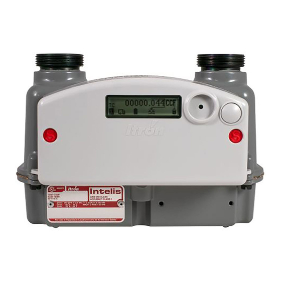
Chapter 2 Intelis Gas Meter The Intelis Gas Meter is a solid state ultrasonic meter featuring an internal safety shut-off valve, built-in temperature conversion, and an integrated 500G communications module. The meter supports the listed functionality. • High flow alarm with optional automatic valve shutoff. -
Page 11: Intelis Gas Meter Models
The Intelis Gas Meter shutoff valve is located in the outlet of the meter. The automatic shutoff valve is a safety feature automatically triggered if the meter is configured for automatic shut off for high flow or high temperature events. -
Page 12: Integrated 500G Communications Module
The integrated 500G RF communications module is designed to operate in either Mobile or OpenWay Riva Network Mode. When the Intelis Gas Meter is operating in Mobile Mode, it may be read by ChoiceConnect handheld readers, mobile collection, or the Itron Mobile Radio connected to a user-supplied computer or Bluetooth device. - Page 13 Innovation, Science, and Economic Development Canada (ISED): RSS-247 and RSS-210 (programming) IC: 864D-INTELISG Measurement Canada: Pending Operational All Intelis Gas Meters operate without the need for an FCC or ISED license Frequency: 902-928 MHz ISM band Program frequency: 908-923.8 MHz Australia...
-
Page 14: Intelis Gas Meter Dimensions
Mobile Collection v3.8.2 Standards Designed in compliance with ANSI B109.1, ANSIB109.0 (draft), and Measurement Canada PS-G-06 Intelis Gas Meter dimensions This section lists the Intelis Gas Meter dimensions. Dimensions are listed in Imperial and Metric units. 8.4 inches 6.4 inches 6.0 inches 5.4 inches... -
Page 15: Chapter 3 Installing The Intelis Gas Meter
The Intelis Gas Meter must be installed with the inlet to the left, the outlet to the right, the meter in a horizontal position and with the LCD facing out. INLET and a flow arrow are marked on the Intelis Gas Meter casing. -
Page 16: Prior To Start-Up
Installing the Intelis Gas Meter Prior to start-up Note: The Intelis Gas Meter is shipped from the factory with the shutoff valve in the open position. Verify the valve is open prior to installing the meter. Confirm the open valve icon... -
Page 17: Removing Or Installing The Pipe Plug
If necessary, change out the meter. 10. Perform a shadow or lock-in test following company or utility procedures. 11. After the Intelis Gas Meter installation testing is complete, purge all air from the gas line including the piping section. -
Page 18: Installing The Pipe Plug
4. Tighten the pipe plug. Do not exceed 50 inch-pounds torque (5.6 Newton Meters). 5. Leak test following your utility's leak test procedure. Intelis Gas Meter Installation Guide TDC-1782-002 Proprietary and Confidential... -
Page 19: Chapter 4 Intelis Gas Meter Lcd Operation
This section provides information about the Intelis Gas Meter LCD. The Intelis Gas Meter LCD This section describes the Intelis Gas Meter LCD menus that are displayed in a pre-defined order (1-8). Note: The Intelis Gas Meter ships in a sealed (locked) state. - Page 20 Before the display moves to the next menu page, all active alarms are displayed. If there are no alarms, NO ALARM displays. For more information about the Intelis Gas Meter display events and alarms, see Intelis Gas Meter LCD display alarms on page 17.
-
Page 21: Intelis Gas Meter Lcd Display Alarms
UMU: Ultrasonic Measurement Unit CRC Intelis Gas Meter LCD display alarms The Intelis Gas Meter reports the following alarms on the LCD. Active alarms are logged. Events that create alarms are logged with a start and an end time. Users may cross check alarms over the network or with a device loaded with FDM Tools. - Page 22 If the Flow measurement hard fail alarm remains active and does not clear, remove the meter and return it to Itron for evaluation. Flow meas. OOR detect. The meter detected flow that is outside the physical range of the measurement sensor.
-
Page 23: Additional Lcd Screen Displays
• Display test. This screen displays after a long button press of 4.8 seconds. The test provides a visual confirmation that the LCD is functioning correctly. Intelis Gas Meter LCD display icons The Intelis Gas Meter LCD display provides the following menu icons as a visual indications of status information. Display icon... -
Page 24: Performing An Lcd Test
Performing an LCD test The Intelis Gas Meter LCD Test is used to confirm the LCD display is functioning properly and that there are no non-displaying pixels that could lead to misinterpretation of a value. • Hold down the meter button longer than 4.8 seconds (long press). -
Page 25: Chapter 5 Proving The Intelis Gas Meter
(PPE). Adhere to guidelines issued by your company in addition to those contained in this document when proving meters. The Intelis Gas Meter Test Mode and a prover station are used to confirm the accuracy of the meter. -
Page 26: Intelis Gas Meter Test Mode
Entering Test Mode Entering Test Mode is accomplished using either the FDM mobile client or through the magnet in the prover connection end of the prover cable. After the Intelis enters Test Mode, the following steps occur. 1. The Intelis Gas Meter logs an Entering Test Mode event. -
Page 27: Exiting Test Mode
2. The Intelis Gas Meter continues to output an optical pulse. Note: While the Intelis Gas Meter is in Test Mode, the LCD refresh rate is more frequent than when the meter is operating in Normal Mode. 3. The Intelis Gas Meter continues to update the normal volume registers. -
Page 28: Tempering The Meter By Exercising
5. Press the clamp buttons on both sides of the SNAP prover. 6. After the Intelis Gas Meter is clamped to the prover, turn on the appropriate nozzles in the center of the screen to exercise the meter. -
Page 29: Setting Up The Prover
1. If you have not previously done so, log on to the prover. Note: If you are proving an Intelis Gas Meter for the first time on the prover or if you are changing proving parameters for the Intelis Gas Meter, you must log on as a Supervisor. - Page 30 Proving the Intelis Gas Meter 5. Select the MeterMfg_Table checkbox. 6. Click in the next available (open) row in the top left table and enter ITRON-RTY for the meter manufacturer. Click off of the table and select Update Table. Intelis Gas Meter Installation Guide TDC-1782-002...
- Page 31 Proving the Intelis Gas Meter Important: If Itron, Actaris, Sprague, or other is listed, it is still necessary to add a new manufacturer name specifically for the Intelis Gas Meter. Itron suggests using ITRON- RTY following the steps listed below. The MFR Type must have the RTY suffix to allow setting and saving the revs desired for any given test and flow rate.
- Page 32 9. Verify or enter the TOLERANCE values for POS, NEG, Slope, Repair, and Meter Size. These settings (values) are customer-specific. 10. Click off the table and select Update Table. 11. Select Exit, select Exit. Intelis Gas Meter Installation Guide TDC-1782-002 Proprietary and Confidential...
-
Page 33: Proving The Intelis Gas Meter
3. Select Intelis 250. 4. Select the correct mode for your meter (TC or NTC). Note: REG is equivalent to NTC. 5. Select the meter results mode (% error, % accuracy, % proof). Intelis Gas Meter Installation Guide TDC-1782-002 Proprietary and Confidential... - Page 34 Proving the Intelis Gas Meter 6. Select the test mode (intest, outtest). 7. Select the optic test method (optic, mag). 8. Select the correct Index (volume per pulse) setting (Imperial, ¼ CF; Metric, 10 dm3). Intelis Gas Meter Installation Guide TDC-1782-002 Proprietary and Confidential...
- Page 35 Note: To reduce cycle time, contact the prover manufacturer to request a 0.10 CF per pulse option added. Testing has shown acceptable results with settings as low as 4 pulses on open and 1 on check but Itron recommends more pulses to obtain better results.
-
Page 36: Proving The Intelis Gas Meter Using The Measurement Systems Proving System
Proving the Intelis Gas Meter 11. Connect the Intelis Gas Meter end of the SNAP pulse prover cable to the Intelis Gas Meter optical port by firmly pressing the aluminum round threads of the cable into the port. Begin by positioning the cable at the 4:30 o'clock position. Tighten the cable to the 6:30 o'clock position. -
Page 37: Temper The Meter By Exercising The Meter
Adjust the proving table to accommodate the height of the Intelis Gas Meter. If necessary, use the Intelis Gas Meter prover stand (Itron part number FIX-7100-001). Place the prover stand on the prover table and set the meter on the stand. -
Page 38: Setting Up The Measurement Systems Prover
4. From the Operate Valves and Observe Sensor Readings screen, press the 1 key or Chuck Valve to clamp the meter in place. 5. After the Intelis Gas Meter is clamped to the prover, turn on the appropriate nozzle in the center of the screen to exercise the meter. - Page 39 3. Select the Meter Model-1 tab. 4. Select the meter model. If the Intelis 250 or Intelis 250 TC are set up in the MMS prover, go to step 10. If the Intelis 250 or Intelis 250 TC is not listed, continue to step 5.
- Page 40 7. Select an existing meter model similar to the new meter as a template. Itron recommends using the S-250 for an Intelis 250 gas meter and an S-250 TC for the Intelis 250 TC gas meter. Select the green bar on the bottom of the screen to use the selected meter as the starting point.
- Page 41 9. Press Enter or click the blue bar at the bottom of the screen to go back to the meter setup menu. 10. Select the Exercise Cycle Duration. The Intelis Gas Meter Exercise Cycle Duration is typically 15 seconds. 11. Set Leak Test to Yes.
- Page 42 • Imperial setting: 0.10 cu ft/rev • Metric setting: 0.01 m3/rev Note: Intelis Gas Meter volume per pulse is in dm3; 10dm3 = 0.01 m3. 14. Verify or enter Flow rates (Air Rate): Open, Check, Other settings. Itron recommended typical settings are listed. For metric flow rates: choose from the flow rate dropdown list options.
- Page 43 15. Select the Proving Method: Index. The options are Index or Magnetic. 16. Select the mode for your meter. Available options are TC or NON-TC. 17. Select the Meter Model-2 tab. Intelis Gas Meter Installation Guide TDC-1782-002 Proprietary and Confidential...
- Page 44 19. Verify or enter the limit values for Check Dif Limits, Monitor Peaks?, and Max Peak. The Check Dif Limits, Monitor Peaks? and Max Peak settings (values) are customer- specific. Intelis Gas Meter Installation Guide TDC-1782-002 Proprietary and Confidential...
- Page 45 Note: The Tangent Adjustment: Tangent Type setting can be any non-blank value. The Tangent Adjustment: Tangent Type value is not used to prove the Intelis Gas Meter. 21. Select the Global tab and Display Method for your meter results. Display Method options are listed.
-
Page 46: Proving The Intelis Gas Meter
23. Press or click the green bar at the bottom of the screen to exit the Meter Setup Menu. Proving the Intelis Gas Meter 1. Connect the Measurement Systems pulse prover cable (Itron part number CFG-7100-500) to the port on the left side of the Measurement Systems prover. - Page 47 2. Connect the Intelis Gas Meter end of the Measurement Systems pulse prover cable to the Intelis Gas Meter by firmly pressing the aluminum round threads of the cable into the port. Begin by positioning the cable at the 4:30 o'clock position. Tighten the cable to the 6:30 o'clock position.
-
Page 48: Proving The Intelis Gas Meter Using The Energy Economics (Eei) Proving System
Proving the Intelis Gas Meter using the Energy Economics (EEI) proving system This section provides the information to set up an Intelis Gas Meter using an EEI proving system. Note: Proving the Intelis Gas Meter requires Energy Economics prover software. - Page 49 Note: Logging on to the EEI prover application requires maintenance level security. 2. Select Maintain > Sensor Maintenance. 3. Clamp the Intelis Gas Meter to the prover and turn on appropriate nozzles in the center column of the Sensor Maintenance window to exercise the meter.
-
Page 50: Setting Up The Eei Prover
Important: If ITRON is not in the Manuf. drop-down list, contact EEI Prover Systems for help in adding ITRON to your EEI Systems Prover. 4. Select Intelis 250, Intelis 250 TC, or the name for the Intelis Gas Meter designated by your company from the Type drop-down list. - Page 51 Proving the Intelis Gas Meter 5. Click the Options tab. The Meter Information > Test Options window opens. 6. Select Eye for the Test Options Sensor. Intelis Gas Meter Installation Guide TDC-1782-002 Proprietary and Confidential...
- Page 52 Proving the Intelis Gas Meter 7. Select Open & Check for the Run Type Test Options. 8. Enter 100 for Flow > Open %. Intelis Gas Meter Installation Guide TDC-1782-002 Proprietary and Confidential...
- Page 53 Important: Required Open flow rates may be different than those shown here. 9. Enter 20 for Flow > Check %. Important: Required Check flow rates may be different than those shown here. 10. Select 1/10 cuft for Hand Size. Intelis Gas Meter Installation Guide TDC-1782-002 Proprietary and Confidential...
-
Page 54: Proving The Intelis Gas Meter
Note: All other settings (Tangents, Ultra Intest Lock, Ultra Adjust Lock and Station) on the Test Options window are not relevant for the Intelis meter Proving the Intelis Gas Meter 1. Connect the EEI pulse prover cable (Itron part number CFG-7100-400) to the EEI prover index eye connector. Intelis Gas Meter Installation Guide TDC-1782-002... - Page 55 Proving the Intelis Gas Meter 2. Connect the Intelis Gas Meter end of the EEI pulse prover cable to the Intelis Gas Meter by firmly pressing the aluminum round threads of the cable into the port. Begin by positioning the cable at the 4:30 o'clock position. Tighten the cable to the 6:30 o'clock position.
-
Page 56: Chapter 6 Adjusting The Intelis Gas Meter Calibration
Chapter 6 Adjusting the Intelis Gas Meter Calibration Intelis Gas Meters are calibrated at the factory prior to shipment. FDM is used if it is necessary to recalibrate the meter. For more information about calibrating the Intelis Gas Meter using FDM, see the FDM Field Service Representatives Guide. For documentation... - Page 57 Adjusting the Intelis Gas Meter Calibration 4. Select Yes. 5. (Mobile endpoint mode only) If you are prompted to enter the Unlock ID, enter the Unlock Intelis Gas Meter Installation Guide TDC-1782-002 Proprietary and Confidential...
- Page 58 Adjusting the Intelis Gas Meter Calibration 6. Select Next. The Parameters screen appears. Intelis Gas Meter Installation Guide TDC-1782-002 Proprietary and Confidential...
- Page 59 Adjusting the Intelis Gas Meter Calibration To demonstrate an example of adjusting the calibration, a sample prover station test results is displayed below and is provided as a reference. Use the following settings to adjust the meter calibration as it relates to your test results: •...
- Page 60 Adjusting the Intelis Gas Meter Calibration 8. Select Next. A progress bar indicates that the meter's calibration is being adjusted. Intelis Gas Meter Installation Guide TDC-1782-002 Proprietary and Confidential...
- Page 61 Adjusting the Intelis Gas Meter Calibration The meter uses the entered values to calculate the required calibration parameters to a target of one of the following, depending on your selected prover station mode: • % Error. 0% open, 0% check •...
-
Page 62: To Seal An Intelis Gas Meter
If the accuracy results are not as expected, repeat the calibration steps. Note: Prover station accuracy is estimated to be +/- 0.15-0.25%. To seal an Intelis gas meter 1. From the Tools menu, select OWR Intelis Gas Riva. 2. Select Test Mode Operations. 3. Select Seal Meter. - Page 63 Adjusting the Intelis Gas Meter Calibration The Seal Meter Operation Successful screen indicates that the meter is sealed. Intelis Gas Meter Installation Guide TDC-1782-002 Proprietary and Confidential...
-
Page 64: To Unseal An Intelis Gas Meter's Umu
Adjusting the Intelis Gas Meter Calibration 4. Select Finish to return to the Tools screen. To unseal an Intelis gas meter's UMU 1. From the Tools menu, select OWR Intelis Gas Riva. 2. Enter the Endpoint ID. 3. Select the Endpoint Mode. - Page 65 Adjusting the Intelis Gas Meter Calibration a) Select Next. The Adjust Calibration screen appears. 11. Click Quit or Finish to return to the Tools screen. Intelis Gas Meter Installation Guide TDC-1782-002 Proprietary and Confidential...
-
Page 66: Chapter 7 Intelis Gas Meter Index Replacement
FDM Tools Reconnect command. Conversely, if the desired state is closed, send an FDM Tools Disconnect command. The Intelis Gas Meter index may only be replaced using the UL classified replacement index kit (Itron part number ERG-7100-105). - Page 67 MTR-7100-005 badge & UL Classification pictures above are correct (cULus mark with File number E323571 as above), and verify the following required text: “Intelis for use in Hazardous Locations only as to Intrinsic Safety”. On the original index (ERG-7100-005), verify the required text marked on the housing: “Model Intelis Gas Meter”.
- Page 68 “S” that is part of the plastic. Make sure this “S” is pointing out of the screw hole, so that it is visible after installation. The replacement procedure is complete. Intelis Gas Meter Installation Guide TDC-1782-002 Proprietary and Confidential...
- Page 69 Intelis Gas Meter Index Replacement Intelis Gas Meter Installation Guide TDC-1782-002 Proprietary and Confidential...
Need help?
Do you have a question about the Intelis and is the answer not in the manual?
Questions and answers