
Related Manuals for ClipperCreek HCS


Summary of Contents for ClipperCreek HCS
- Page 1 ClipperCreek, Inc. Innovative Infrastructure for Electric and Hybrid Vehicles User Manual • • • • • • • Model HCS...
- Page 2 PLEASE NOTE This user manual includes the latest information at the time of printing. ClipperCreek, Inc. reserves the right to make changes to this product without further notice. Changes or modifications to this product by other than an authorized service facility may void the product warranty.
-
Page 3: Table Of Contents
OPERATION ....................15 The HCS Front Panel INSTALLATION - SERVICE CONNECTIONS ........17 MOUNTING PROCEDURES ..............25 HCS EVSE Mounting for Hollow-Wall Construction HCS EVSE Mounting for Solid-Wall Construction MOUNTING THE SAE J1772 CONNECTOR HOLSTER ....28 CHARGE CABLE WRAP GUIDELINES ..........30 WIRING INSTRUCTIONS (Hardwired HCS) ........ - Page 4 Drape the Charge Cable Loosely Around the HCS Enclosure ......30 Wiring the HCS in a Junction Box ..............31 10. Preferred Orientation of the NEMA Receptacles Below the Plug-in HCS ...33 11. Locking the SAE J1772 Connector with Padlock Included ......35 12.
-
Page 5: Important Safety Instructions
HCS User Manual IMPORTANT SAFETY INSTRUCTIONS Carefully read these instructions and the charging instructions in your vehicle owner’s handbook before charging your electric vehicle. The following symbols may be found in this manual or on labels affixed to the Electric Vehicle Supply Equipment (EVSE): NOTE: This means pay particular attention. -
Page 6: Instructions Pertaining To A Risk Of Fire Or Electric Shock
Instructions Pertaining to a Risk of Fire or Electric Shock When using the HCS, basic electrical safety precautions should be followed: • Use this EVSE to charge electric vehicles equipped with an charge port only. - Page 7 Do not allow children to operate this device. Adult supervision is mandatory when children are in proximity to an EVSE that is in use. Additional Instructions for Plug-In HCS Configurations 240V plugs are specifically designed for occasional • relocation, such as moving from one home to another home.
- Page 8 HCS User Manual Instructions se Rapportant à un Risque d’Incendie ou de Choc Électrique Lorsque l’utilisation de la HCS, précautions fondamentale de sécurité électrique doivent être suivies: • Utilisez cette station de recharge pour charger les véhicules électriques équipés d’un SAE J1772 port de recharge ™...
- Page 9 Ne pas laisser les enfants utiliser cet appareil. Supervision d’un adulte est obligatoire lorsque des enfants sont à proximité d’une station de recharge qui est en cours d’utilisation. Instructions supplémentaires pour les configurations HCS enfichables • Les prises de 240V sont spécialement conçues pour les relocalisations occasionnelles, tel que le déménagement...
- Page 10 HCS User Manual Instrucciones relacionadas con un riesgo de incendio o descarga eléctrica Al utilizar el HCS, se deben seguir las siguientes precauciones básicas de seguridad eléctrica: • Utilice este EVSE para cargar vehículos eléctricos equipados con un puerto de carga SAE J1772 únicamente.
- Page 11 HCS User Manual Instrucciones adicionales para configuraciones de HCS enchufables • Los tomacorrientes de 240V están específicamente diseñados para reubicaciones ocasionales, como la mudanza de una casa a otra. • Por su seguridad personal, el interruptor de circuito DEBE estar apagado antes de enchufar Y/O desenchufar dispositivos de 240V (incluyendo este dispositivo EVSE).
-
Page 12: Additional Safety Instructions
HCS User Manual Additional Safety Instructions WARNING: Turn off power to the EVSE at the circuit breaker panel before moving, servicing or cleaning the unit. AVERTISSEMENT: Couper l’alimentation de l’EVSE au niveau du panneau de disjoncteurs avant de déplacer, d’effectuer la maintenance ou de nettoyer l’appareil. - Page 13 NOTE: Vehicles which conform to the SAE J1772 standard for communication can inform the charge station that they require an exhaust fan. The HCS is not equipped to control ventilation fans. Do not charge the vehicle with the HCS if ventilation is required.
-
Page 14: Fcc Information
RF-producing equipment (such as digital phones, RF communications equipment, etc.) could affect operation. If interference to the EVSE is suspected, the following steps should be taken before consulting a ClipperCreek Sales or Service ® Representative for assistance: 1. -
Page 15: Operation
Normally, the vehicle will immediately request a charge using a special communication line in the cable. Within a few seconds the Green “Charging” light on the face of the HCS will turn on and the charging cycle will begin. After an average driving day the vehicle battery pack will require several hours to recharge completely. -
Page 16: The Hcs Front Panel
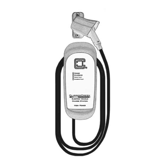
HCS User Manual Figure 1: HCS Front The HCS Front Panel Panel The front panel on the HCS has four indicator lights, as shown in Figure 1. POWER (Amber), indicates that power is available to the HCS. CHARGING (Green), indicates that... -
Page 17: Installation - Service Connections
Código Eléctrico Nacional, ANSI/NFPA 70 (EE.UU) o el Código Eléctrico Canadiense C22.2 NO. 280- 13 (Canadá). Table 2: Service Connections for Standard & Ruggedized HCS HCS Model Connection/Receptacle Type Circuit Breaker Rating... - Page 18 (generalmente utilizado como Neutro) debe estar conectado a tierra en algún punto del sistema. Una conexión Neutra no es requerida por la HCS. Sólo la Línea 1, Línea 2, y la Conexión a Tierra son necesarias, tal y como se muestra en la Figura 3.
- Page 19 HCS User Manual CAUTION: If a 240V 3-phase feed is from a Delta- connected secondary, the leg used must have a center-tap. That tap must be Grounded. Only the two phases on either side of the center-tapped leg can be used. See Figure 4.
- Page 20 Notice that L1, L2, & Ground are labeled on each diagram. Those transformer outputs correspond to the same inputs on the HCS. Also, each of the two 3-phase diagrams shows an L3 output, which is not used. Do not connect all three phases of a 3-phase secondary to the HCS.
- Page 21 HCS User Manual The following diagrams illustrate the three service transformer secondary connections most common in North America. Figure 2: 220/240V Single Phase 120V 240V NEUTRAL (NOT USED) 120V GROUND Figure 3: 208V 3-Phase, Wye-Connected L3 (NOT USED) 120V 208V...
- Page 22 NOTA: Con un secundario conectado en “Y”, cualquiera de las dos piernas puede ser utilizada para proporcionar 208V a la HCS. Por ejemplo, L1 y L2, o L1 y L3, o L2 y L3. Deje la pierna no inutilizada abierta. No la conecte a la Barra Neutro, o a Tierra.
- Page 23 HCS. No “Neutral” point is available to be connected to ground for ground-fault protection. The HCS will not allow the contactor to close if it does not sense the presence of a Ground wire connected to a...
- Page 24 être utilisé avec la HCS. Aucun point “Neutre” est disponible pour être connecté à Mise à la Terre pour protection de défaut à la terre. Le HCS ne permettra pas le contacteur de fermer si elle ne détecte pas la présence d’un fil de Masse connecté...
-
Page 25: Mounting Procedures
• On the hardwired HCS, the three service conductors are shielded by 3' (1 m) of flexible conduit at the bottom of the unit. The HCS must be positioned such that this conduit can reach a nearby junction box. •... -
Page 26: Hcs Evse Mounting For Hollow-Wall Construction
• Size ¼”- 20 lag screws are recommended for mounting the HCS to a wooden structure. Pre-drill appropriately sized pilot holes to allow the lag screw to grip the wooden structure while preventing the wood from cracking or splintering while the screw is fastened. -
Page 27: Hcs Evse Mounting For Solid-Wall Construction
• Machine screw size ¼”- 20 hardware is recommended for mounting the HCS. Screw shafts of at least 2” (5.1 cm) are recommended. The HCS plastic angle washer hole size is ⅜” (1 cm) in diameter, ensure the screw heads are of a larger diameter. -
Page 28: Mounting The Sae J1772 Connector Holster
Use a ruler or template to mark hole locations on the mounting surface. • The vertical alignment of the HCS and SAE J1772 connector holster mounting holes allows for the convenient mounting of both components onto the same post or wall structure. For example, the holster may be mounted directly above the HCS. -
Page 29: Mounting The Sae J1772 Connector Holster Using The Exterior Wood Screws And Washers
HCS User Manual Figure 7: Mounting the SAE J1772 Connector Holster Using the Exterior Wood Screws and Washers... -
Page 30: Charge Cable Wrap Guidelines
HCS User Manual CHARGE CABLE WRAP GUIDELINES The HCS enclosure body is sculpted to allow the charge cable to be wrapped around it for convenient storage as well as to keep the bulk of the cable off of the ground and out of the way. As the... -
Page 31: Wiring Instructions (Hardwired Hcs)
HCS User Manual WIRING INSTRUCTIONS (Hardwired HCS) Route the HCS conduit to a nearby junction box. Use the included ½” trade size watertight conduit fitting and sealing washer to provide a moisture-resistant seal between the conduit fitting and the junction box. If necessary, drill a ⅞” diameter hole to accommodate the conduit fitting. - Page 32 Noir: Ligne 1 (120V AC à Mise à la Terre) Rouge: Ligne 2 (120V AC à Mise à la Terre) Los tres conductores de servicio HCS-15, 20, 25, 30 o 40 sumin- istrados utilizan un cable de cobre trenzado de 10 AWG 90ºC. Los tres conductores de servicio HCS-50, HCS-60 y HCS-80 suminis- trados utilizan cable de cobre trenzado de 8 AWG, 90ºC.
-
Page 33: Receptacle Instructions (Plug-In Hcs)
HCS User Manual RECEPTACLE INSTRUCTIONS (Plug-In HCS) The plug-in HCS is fitted with either a NEMA 14-50 or 6-50 plug extending from the bottom of the HCS enclosure. Regulations limit this plug to a maximum of 12 inches (30.5 cm) in length, including the plug head. -
Page 34: Grounding Instructions
HCS Plug-in EVSE Grounding The plug-in HCS is equipped with a supply cord having an equipment grounding conductor and a grounding plug. The plug must be plugged into an appropriate receptacle that is properly installed and grounded in accordance with all local codes and ordinances. -
Page 35: Using The Padlock
HCS User Manual USING THE PADLOCK A padlock with three keys is included with ClipperCreek EVSE when the connector style includes a lock hole. This rust-proof, solid brass padlock is provided to secure the charge connector to prevent the vehicle’s charge from being interrupted via removal. -
Page 36: Moving & Storage Instructions
HCS to or disconnecting an HCS from the service lines. Likewise, always turn off input power to the EVSE at the circuit breaker panel prior to plugging an HCS into or unplugging an HCS from a NEMA socket. -
Page 37: Optional Features
HCS User Manual OPTIONAL FEATURES If the HCS unit being installed is equipped with an optional feature such as COSMOS, Share2, or ChargeGuard use the provided HCS Optional Features User Manual. A digital copy of the HCS Optional Configurations User Manual can be found at: clippercreek.com/installation-manuals... -
Page 38: Maintenance
HCS User Manual MAINTENANCE The HCS requires no periodic maintenance other than occasional cleaning. WARNING: To reduce the risk of electrical shock or equipment damage, exercise caution while cleaning the EVSE and the EV charge connector cable. 1. Turn off the EVSE at the circuit breaker. -
Page 39: Customer Support
NUMBER AND SERIAL NUMBER AVAILABLE WHEN CALLING. This information is printed on the label on the side of the HCS enclosure. If a call is made after business hours or on weekends, please leave a name, telephone number, the unit serial number, and a brief description of the problem. -
Page 40: Specifications
25, 30 or 40: L1, L2 and Ground use 3 feet of 10AWG, 90ºC copper wire. Pre-installed supplied input conductors of the HCS-50, HCS-60, and HCS-80: L1, L2 and Ground use 3 feet of 8AWG, 90ºC copper wire. Voltage Range:... - Page 41 HCS User Manual Weight: HCS-15, 20, 25, 30, 40 or HCS-40P with 40A SAE J1772 connector and 25’ length of cable: 6.1kg (13.5 lbs) HCS-20R, HCS-30R, or HCS-40R with 32A SAE J1772 connector and 25’ length of cable: 6.1kg (13.5 lbs) HCS-50 or HCS-50P with 40A SAE J1772 connector and 25’...
-
Page 42: Warranty Information (3 Year Standard)
If this product is not as warranted, your sole and exclusive remedy shall be repair or replace as provided above. In no event will ClipperCreek, any of its authorized sales and service representatives, or its parent company be liable to customer or any third party for any damages in excess of the purchase price of the product. -
Page 43: Warranty Information (5 Year Ruggedized)
ClipperCreek or an authorized ClipperCreek representative or dealer has been advised of the possibility of such damages or of any claim by any other party. - Page 44 ClipperCreek, Inc. 11850 Kemper Rd., Suite E Auburn, CA 95603 www.ClipperCreek.com (877) 694-4194...
Need help?
Do you have a question about the HCS and is the answer not in the manual?
Questions and answers