
Related Manuals for ClipperCreek HCS


Summary of Contents for ClipperCreek HCS
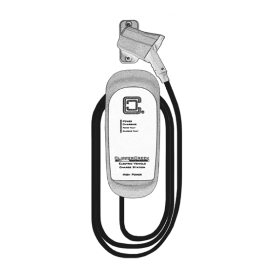
- Page 1 ClipperCreek, Inc. Innovative Infrastructure for Electric and Hybrid Vehicles User Manual • • • • • • • Model HCS...
- Page 2 PLEASE NOTE This user manual includes the latest information at the time of printing. ClipperCreek, Inc. reserves the right to make changes to this product without further notice. Changes or modifications to this product by other than an authorized service facility may void the product warranty.
-
Page 3: Table Of Contents
OPERATION ...................10 The HCS Front Panel INSTALLATION - SERVICE CONNECTIONS ......12 MOUNTING PROCEDURES .............18 HCS EVSE Mounting for Hollow-Wall Construction HCS EVSE Mounting for Solid-Wall Construction WIRING INSTRUCTIONS (Hardwired HCS) ......22 RECEPTACLE INSTRUCTIONS (Plug-In HCS) ......24 GROUNDING INSTRUCTIONS ............25... - Page 4 ChargeGuard EX ............42 24. Mounting the SAE-J1772 Connector Holster Using the Exterior Wood Screws and Washers .............46 25. Drape the Charge Cable Loosely Around the HCS Enclosure ......47 Tables Front Panel LED Information................ 11 Service Connections for Standard and Ruggedized HCS ......12 HCS Series Optional Configurations .............28...
-
Page 5: Important Safety Instructions
électriques et les pratiques courantes de prévention des accidents. Instructions Pertaining to a Risk of Fire or Electric Shock When using the HCS, basic electrical safety precautions should be followed: • Use this EVSE to charge electric vehicles equipped with an SAE-J1772 charge port only. - Page 6 EVSE that is in use. Instructions se Rapportant à un Risque d’Incendie ou de Choc Électrique Lorsque l’utilisation de la HCS, précautions fondamentale de sécurité électrique doivent être suivies: • Utilisez cette station de recharge pour charger les véhicules électriques équipés d’un SAE-J1772...
- Page 7 HCS User Manual • SAE-J1772 Assurez-vous que le câble de recharge sur la station de recharge est positionné de telle sorte qu’il ne sera pas piétiné, accroché plus de, ou autrement endommagé ou de subir le stress. • Ce produit ne contient aucune pièce réparable par l’utilisateur.
- Page 8 EVSE that they require an exhaust fan. The HCS is not equipped to control ventilation fans. Do not charge the vehicle with the HCS if ventilation is required. Véhicules qui sont conformes à la norme SAE-J1772 communication peuvent informer la station de recharge qu’ils nécessitent un ventilateur d’extraction.
-
Page 9: Fcc Information
RF communications equipment, etc.) could affect operation. If interference to the EVSE is suspected, the following steps should be taken before consulting a ClipperCreek Sales or Service Representative for assistance: 1. Reorient or relocate nearby electrical appliances or equipment during charging. -
Page 10: Operation
Normally, the vehicle will immediately request a charge using a special communication line in the cable. Within a few seconds the green “Charging” light on the face of the HCS will turn on and the charging cycle will begin. After an average driving day the vehicle battery pack will require several hours to recharge completely. -
Page 11: The Hcs Front Panel
HCS User Manual Figure 1: HCS Front The HCS Front Panel Panel The front panel on the HCS has four indicator lights, as shown in Figure 1. POWER (yellow), indicates that power is available to the HCS. CHARGING (green), indicates that... -
Page 12: Installation - Service Connections
The centerpoint of the three phases (usually used as Neutral) must be grounded somewhere in the system. A Neutral connection is not required by the HCS. Only Line 1, Line 2, and Ground are required, as shown in Figure 3. - Page 13 (généralement utilisé comme Neutre) doit être mis à la terre quelque part dans le système. Une connexion Neutre n’est pas exigée par la HCS. Seulement ligne 1, ligne 2, et Mise à la Terre sont nécessaires, comme le montre la Figure 3.
- Page 14 Notice that L1, L2, & Ground are labeled on each diagram. Those transformer outputs correspond to the same inputs on the HCS. Also, each of the two 3-phase diagrams shows an L3 output, which is not used. Do not connect all three phases of a 3-phase secondary to the HCS.
-
Page 15: V Single Phase
HCS User Manual The following diagrams illustrate the three service transformer secondary connections most common in North America. Figure 2: 220/240V Single Phase 120V 240V NEUTRAL (NOT USED) 120V GROUND Figure 3: 208V 3-Phase, Wye-Connected L3 (NOT USED) 120V 208V... -
Page 16: V 3-Phase, Delta-Connected, W/Center-Tap On One Leg
NOTE: With a wye-connected secondary, any two of the legs can be used to provide 208V to the HCS. For example, L1 & L2, or L1 & L3, or L2 & L3. Leave the unused leg open. Do not connect it to a Neutral bar, or to Ground. Be sure the center point is grounded to Earth somewhere in the system. - Page 17 HCS. No “Neutral” point is available to be connected to ground for ground-fault protection. The HCS will not allow the contactor to close if it does not sense the presence of a Ground wire connected to a “Neutral”...
-
Page 18: Mounting Procedures
• On the plug-in HCS, the NEMA plug head is connected by one foot of cable (including the plug head) to the bottom side of the HCS. The plug-in HCS must be positioned such that this plug can safely be inserted into a wall-mounted NEMA socket. -
Page 19: Hcs Evse Mounting For Hollow-Wall Construction
• Size ¼”- 20 lag screws are recommended for mounting the HCS to a wooden structure. Pre-drill appropriately sized pilot holes to allow the lag screw to grip the wooden structure while preventing the wood from cracking or splintering while the screw is fastened. -
Page 20: Hcs Evse Mounting For Solid-Wall Construction
• Machine screw size ¼”-20 hardware is recommended for mounting the HCS. Screw shafts of at least 2” are recommended. The HCS plastic angle washer hole size is 3/8” in diameter, ensure the screw heads are of a larger diameter. Place appropriately sized washers between the screw heads and the HCS enclosure mounting flanges. -
Page 21: Mounting The Hcs To A Solid-Wall
HCS User Manual Figure 6: Mounting the HCS to a Solid-Wall... -
Page 22: Wiring Instructions (Hardwired Hcs)
HCS User Manual WIRING INSTRUCTIONS (Hardwired HCS) Route the HCS conduit to a nearby junction box. Use the included ½” trade size watertight conduit fitting and sealing washer to provide a moisture-resistant seal between the conduit fitting and the junction box. If necessary, drill a 7/8” diameter hole to accommodate the conduit fitting. - Page 23 HCS User Manual Les trois conducteurs de service HCS-50, HCS-60 et HCS-80 fournis utilisent des câbles toronnés de calibre 8 AWG, 90ºC fil de cuivre. L’isolation de chaque conducteur est un code couleur pour l’installation de 240V AC norme: Vert: Mise à...
-
Page 24: Receptacle Instructions (Plug-In Hcs)
HCS User Manual RECEPTACLE INSTRUCTIONS (Plug-In HCS) The plug-in HCS is fitted with either a NEMA 14-50 or 6-50 plug extending from the bottom of the HCS enclosure. Regulations limit this plug to a maximum of 12 inches in length, including the plug head. -
Page 25: Grounding Instructions
HCS Plug-in EVSE Grounding The plug-in HCS is equipped with a supply cord having an equipment grounding conductor and a grounding plug. The plug must be plugged into an appropriate receptacle that is properly installed and grounded in accordance with all local codes and ordinances. -
Page 26: Using The Padlock
HCS User Manual USING THE PADLOCK A padlock with three keys is included with ClipperCreek EVSEs when the connector style includes a lock hole. This rust-proof, solid brass padlock is provided to secure the charge connector to prevent the vehicle’s charge from being interrupted via removal. -
Page 27: Moving & Storage Instructions
HCS to or disconnecting an HCS from the service lines. Likewise, always turn off input power to the EVSE at the circuit breaker panel prior to plugging an HCS into or unplugging an HCS from a NEMA socket. -
Page 28: Hcs Optional Configurations
HCS User Manual HCS OPTIONAL CONFIGURATIONS Overview The HCS Series EVSE can be built with additional functionality including abilities for access control, shared circuit power, and load management. These features can often be used together, but must be built to order. Reference the chart below to verify which combination of HCS expanded functionalities would best suit specific requirements. -
Page 29: Chargeguard ® Enabled Hcs
Refer ® to these instructions to operate a ChargeGuard enabled HCS EVSE. 1. Connect the HCS EVSE to the vehicle with the SAE-J1772 connector. 2. To enable charging: a) Insert the key into the switch located on the right side of the HCS EVSE. - Page 30 HCS User Manual ® Figure 12: ChargeGuard (ON or Enabled Position: Charging is enabled.) 4. To restrict access: a) Turn the key counterclockwise 90° as shown in Figure b) Remove the key. c) If a vehicle is connected and charging, that vehicle will continue to charge as long it remains connected to the EVSE.
-
Page 31: Replacement Keys
The EVSE will be enabled for as long as the vehicle remains plugged in. The EVSE will reset when the vehicle connector is unplugged.) Replacement Keys Should replacement keys be required, contact the ClipperCreek office at (877) 694-4194. Please have the EVSE serial number available for reference. ®... -
Page 32: Chargeguard Ex
EX Enabled HCS ChargeGuard EX provides a simple interface to connect the ClipperCreek HCS EVSE to an existing building access control or other third party access control system. With ChargeGuard a momentary contact closure driven by successful authentication in an access control system can activate the HCS ChargeGuard EX enabled station for a single charging session. - Page 33 Yellow Wire Orange Wire Please refer to these instructions to operate the ChargeGuard enabled HCS EVSE: 1. Connect the HCS EVSE to the vehicle with the SAE- J1772 connector. 2. Enable charging by using access control. 3. The “CHARGING” LED light will illuminate green on the...
-
Page 34: Share2 ® Enabled Hcs
(not included) to secure the Blue and Brown wires to the opposing White wire as indicated by the black dots in Figure 16. NOTE: Each HCS comes with 3 feet of conduit containing the ® communication wires. When using Share2 , HCS stations can be placed up 100 feet apart. -
Page 35: Verify Share2 ® Function Is Working Properly
10 seconds before full circuit power will be available to the other vehicle. ® Share2 Operating Instructions 1. Connect Vehicle #1 to either HCS #1 or HCS #2 with the corresponding SAE-J1772 connector. Vehicle #1 will have access to the full power available through that circuit. -
Page 36: Share2
HCS User Manual ® Figure 17: Share2 Connect Vehicle #1 HCS 1 HCS 2 Vehicle 1 Vehicle 2 Full Circuit Power Available (100%) Not charging (0%) ® Figure 18: Share2 Connect Vehicle #2 HCS 1 HCS 2 Vehicle 1 Vehicle 2... - Page 37 HCS User Manual ® Figure 19: Share2 One of the Vehicles Disconnects or Completes Charging HCS 1 HCS 2 Vehicle 1 Vehicle 2 Not Charging (0%) Full Circuit Power Available (100%)
-
Page 38: Cosmos ® Load Management Enabled Hcs
Wiring Instructions 1. Determine whether the Digital Interface will be used with or without the Serial Interface in the installation. NOTE: Contact ClipperCreek to obtain an NDA for documentation describing the Communication Protocol for the Serial Interface. 2. Confirm power to the EVSE is off and locked out. -
Page 39: Serial And Digital Interface
HCS User Manual ® Table 4: COSMOS Wiring Instructions Wire Name Input/Output Interface Wire Color Ratings Isolated Ground Input Black Ground Serial Output Yellow Interface 3.3 - 5V DC (Isolated Input Orange UART) Isolated 3.3-5V Input 3.3 - 5V DC, 20mA... -
Page 40: Cosmos
HCS User Manual ® COSMOS Digital Interface Connection The Digital Interface wiring must be completed regardless of whether or not the Serial Interface is to be utilized in the installation. The Power Level is determined by the state of the... -
Page 41: Cosmos
This output is designed to be compatible with the +12V/1kΩ Load Management High/Low or High/Off input terminal of the ClipperCreek CS series products as well as the +5V/10kΩ Load Management 0 or Load Management 1 of another ClipperCreek HCS equipped with the ®... -
Page 42: Cosmos
COSMOS Load Management Enabled HCS section remain the same. ® Activation of the COSMOS ChargeGuard EX enabled HCS unit can be enabled with items such as: 1. An RFID key card 2. An External button 3. A Remote connection ®... -
Page 43: Cosmos Chargeguard Ex Activation Instructions
HCS User Manual ® COSMOS ChargeGuard EX Activation Instructions Connect the charge cord to the vehicle Momentarily (> 0.1 second) ground the EX-Activate wire (Violet) to ground (Green and Grey) ® This COSMOS ChargeGuard EX activation will make the station available for charging until it is disconnected from the vehicle. -
Page 44: Maintenance
HCS User Manual MAINTENANCE The HCS requires no periodic maintenance other than occasional cleaning. WARNING: To reduce the risk of electrical shock or equipment damage, exercise caution while cleaning the unit and the EV charge connector cable. 1. Turn off the EVSE at the circuit breaker before cleaning. -
Page 45: Mounting The Sae-J1772
The vertical alignment of the HCS and SAE-J1772 connector holster mounting holes allows for the convenient mounting of both components onto the same post or wall structure. For example, the holster may be mounted directly above the HCS. • Place the SAE-J1772 connector holster such that both mounting holes can take advantage of solid structural framing inside of the wall or a strong wall surface such as plywood. -
Page 46: Mounting The Sae-J1772
HCS User Manual Figure 24: Mounting the SAE-J1772 Connector Holster Using the Exterior Wood Screws and Washers... -
Page 47: Charge Cable Wrap Guidelines
HCS User Manual CHARGE CABLE WRAP GUIDELINES The HCS enclosure body is sculpted to allow the charge cable to be wrapped around it for convenient storage as well as to keep the bulk of the cable off of the ground and out of the way. As the... -
Page 48: Customer Support
NUMBER AND SERIAL NUMBER AVAILABLE WHEN CALLING. This information is printed on the label on the side of the HCS enclosure. If a call is made after business hours or on weekends, please leave a name, telephone number, the unit serial number, and a brief description of the problem. -
Page 49: Specifications
25, 30 or 40: L1, L2 and Ground use 3 feet of 10AWG, 90ºC copper wire. Pre-installed supplied input conductors of the HCS-50, HCS-60, and HCS-80: L1, L2 and Ground use 3 feet of 8AWG, 90ºC copper wire. Voltage Range:... - Page 50 HCS User Manual Weight: HCS-15, 20, 25, 30, 40 or HCS-40P with 40A SAE-J1772 connector and 25’ length of cable: 6.1kg (13.5 lbs) HCS-20R, HCS-30R, or HCS-40R with 32A SAE-J1772 connector and 25’ length of cable: 6.1kg (13.5 lbs) HCS-50 or HCS-50P with 40A SAE-J1772 connector and 25’...
-
Page 51: Warranty Information (3 Year Standard)
If this product is not as warranted, your sole and exclusive remedy shall be repair or replace as provided above. In no event will ClipperCreek, any of its authorized sales and service representatives, or its parent company be liable to customer or any third party for any damages in excess of the purchase price of the product. -
Page 52: Warranty Information (5 Year Ruggedized)
ClipperCreek or an authorized ClipperCreek representative or dealer has been advised of the possibility of such damages or of any claim by any other party. - Page 53 HCS User Manual This page was left intentionally blank.
- Page 54 HCS User Manual This page was left intentionally blank.
- Page 55 HCS User Manual This page was left intentionally blank.
- Page 56 ClipperCreek, Inc. 11850 Kemper Rd., Suite E Auburn, CA 95603 www.ClipperCreek.com (877) 694-4194...
Need help?
Do you have a question about the HCS and is the answer not in the manual?
Questions and answers