Table of Contents
Advertisement
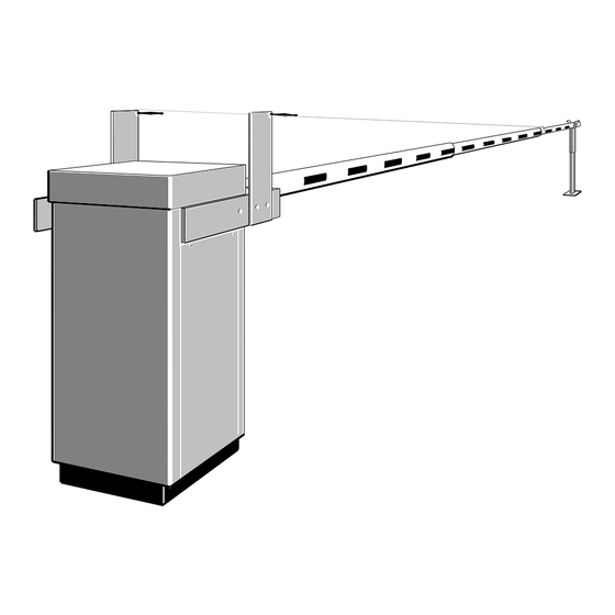
BL 52 – BL 53
Electrical rising barrier
BL52 / BL53
This handbook is also valid for the customised equipment BLG76, which will be regarded as BL52 with netting.
OPERATING MANUAL
(translated from the French original notice)
The information contained in this document is the property of Automatic Systems and is confidential. The recipient shall refrain from using it for any purpose other than the use of the products or the
execution of the project to which it refers, and from communicating it to third parties without Automatic Systems' prior written agreement. Document subject to change without notice.
BL5x-MT-EN-13
1/56
page
Advertisement
Table of Contents

Summary of Contents for Ier Automatic Systems BL52
- Page 1 BL 52 – BL 53 Electrical rising barrier BL52 / BL53 This handbook is also valid for the customised equipment BLG76, which will be regarded as BL52 with netting. OPERATING MANUAL (translated from the French original notice) The information contained in this document is the property of Automatic Systems and is confidential. The recipient shall refrain from using it for any purpose other than the use of the products or the execution of the project to which it refers, and from communicating it to third parties without Automatic Systems’...
- Page 2 Revision page Date Written by Checked by Nature of the modification Apr 05, 2007 SD + JB - Replacement of D1 control board by AS1320 (version 3.6 of the program) => ch 3 added. July 19, 2007 - Update of the balance table (ch. 5.5). 13 nov.
-
Page 3: Table Of Contents
Table of contents SAFETY WARNINGS ........................... 4 GENERAL ..............................5 2.1. General view ..............................5 2.2. Access to internal components ........................6 2.3. Switching off the equipment .......................... 7 2.4. General conditions of use ..........................8 2.5. Emergency operation ............................ 8 2.5.1. -
Page 4: Safety Warnings
SAFETY WARNINGS WARNING: BL52/BL53 OUR RISING BARRIER TYPE COMPRISES A MECHANISM AND VARIOUS ELECTRICAL COMPONENTS NY NEGLIGENCE DURING AN INTERVENTION IN THE MACHINE MAY SERIOUSLY ENDANGER YOUR SAFETY S SOON AS YOU OPEN THE HOUSING SWITCH OFF THE CIRCUIT BREAKER (4:1) (1:2). -
Page 5: General
GENERAL 2.1. General view 1:12 1:10 1:11 Legend: 1:1 Left-hand door 1:2 Right-hand door 1:3 Safety locks with keys 1:4 Arm bracket (BL52) 1:5 Arm bracket (BL53) 1:6 Hood 1:7 Housing 1:8 Fixing brackets 1:9 Stainless steel heater 1:10 Emergency crank hole 1:11 Emergency crank handle 1:12 Commercial identification plate The information contained in this document is the property of Automatic Systems and is confidential. -
Page 6: Access To Internal Components
2.2. Access to internal components Control board with cover Control board guides Driving belt Spring Limit switches Serial plate Crank switch Motor Gearbox 2:10 Driving rod 2:11 Heater 2:12 Fixing latches 2:13 Driving shaft 2:14 Abutment The information contained in this document is the property of Automatic Systems and is confidential. The recipient shall refrain from using it for any purpose other than the use of the products or the execution of the project to which it refers, and from communicating it to third parties without Automatic Systems’... -
Page 7: Switching Off The Equipment
2.3. Switching off the equipment As soon as you open the housing, switch off the power by switching off the magneto-thermal circuit breaker (4:1) located behind the side door (1:1). 4:1 Main circuit breaker 4:2 Ground terminal Fig. 4 The information contained in this document is the property of Automatic Systems and is confidential. -
Page 8: General Conditions Of Use
2.4. General conditions of use Your rising barrier type BL52/BL53 has been designed to operate in any kind of climatic environment, from -35°C to +50C (thanks to heating resistance), with up to 95% of relative humidity. 2.5. Emergency operation ... -
Page 9: In Case Of Breakdown
2.5.2. In case of breakdown The obstacle does Liquid crystal display is Check the general power supply. not move Check the voltage on the circuit breaker (4:1), and check if this late is on. Check the connection of the control wires referring to the electrical diagram, as well as their tightening. -
Page 10: As1320 Control Board
AS1320 Control board (Extract from AS1320 technician manual) 5:1. Fuses 5:2. Stabilised power supply indicator light 5:3. Menu display screen 5:4. Menu navigation keys 5:5. RJ45 communication connector 5:6. In/Out control connector blocks 5:7. 5 green LEDs (lit when the board is on) 5:8. - Page 11 The control board is the interface between the user and the barrier, which manages all the latter’s actions, including any possible options. Note: Hereinafter are presented only the functions accessible in Simplified mode and sufficient for daily use of the equipment. For a detailed description of all the functions, their parameter setting, etc, please refer to the manual dedicated to the board (available on request)..
-
Page 12: Prdstd - Bl_Xxx" Menu: Diagnosis And Monitoring
“PRDSTD – BL_xxx” Menu: Diagnosis and monitoring 3.1. This screen appears when the unit is turned on and when there has not been any navigation through the menus in Simplified mode for 100 seconds. Program name Choose a language Date (DD/MM) using the ◄... - Page 13 Parameter Values Description Display of the last 100 events (use ► the ▲ and keys to view preceding events). For the first two seconds, the event number (00 for the last event recorded (= most recent), 01 for the preceding event, and so on), as well as the date (year-month-day) and time (hours- minutes-seconds) of creation are displayed.
- Page 14 Parameter Values Description Time Adjust Modification of the date and time. Access Level Chg Change to the access level. OOS Restore Apparatus put back in service (after it has been out of service) => see the RestartMode parameter under the OPTIONS menu. Test Intensive Activation of the intensive test.
- Page 15 Parameter Values Description Download Chg Lv2 Downloading a version of the control board program that differs from the one previously installed. As the difference is of level 2 (modification of the version or the evolution), all of the parameters are returned to their default values.
- Page 16 Parameter Values Description Curve BL46 AVR Change in the type of barrier: Selection of curve BL46AVR (Barrier Type parameter under the QUICK START menu). Curve BL46 SR Change in the type of barrier: Selection of curve BL46SR (Barrier Type parameter under the QUICK START menu). Curve RSB 70&71 Change in the type of equipment: Selection of curve RSB 70&71 (Barrier Type parameter under the QUICK START menu).
- Page 17 Parameter Values Description Reader B Hold Check why the Reader B command is being maintained on the control board connector block Position Fail The type of sensor selected is Analogue Sensor (QUICK START ► menu Positioning); nevertheless, the obstacle still has to be activated (►...
-
Page 18: Quick Start" Menu: Quick Configuration
3.2. "QUICK START" menu: quick configuration This menu inspects the parameters that have to be configured before the equipment may be used. Parameter Values Description Definition of the mode of operation of Presence PS1 Function 0 (by default) to 7 Sensor 1: see table below. - Page 19 Parameter Values Description Positioning Definition of the type of sensor used to position the obstacle. Limit Switches To be selected if the open/close position of the obstacle is (by default) determined by limit switches. Analog. Sensor To be selected if the position of the obstacle is determined by an analogue sensor.
- Page 20 Parameter Values Description Value 0 Detect Activation failed because the analogue sensor returned a measurement of zero. As this value is invalid, check: the sensor’s wiring (in the sensor as well as on the control board's connector blocks); whether is sensor is too close to the cam; ...
- Page 21 Parameter Values Description BL 46 AVR Parameter to select for a BL46 with automatic opening of the arm in case of power cut. Arm Length Specification of the arm mounted on the barrier; this allows the program to automatically modify the opening and closing curves.
- Page 22 Parameter Values Description The obstacle remains mechanically locked, thanks to the (by default, except for position of the transmission elements between them. BL4x) Nevertheless, it is possible to unlock it manually using a lever or a crank. The obstacle is unlocked: a pulse is given to take the (by default for BL4x transmission elements out of alignment;...
- Page 23 Parameter Values Description Exploitation Operating modes for the opening, closing and STOP commands. The commands follow this decreasing order of priority: STOP (stop) Lock OP (lock open) Lock CL (lock close) (open) (close) The presence sensors and reader inputs are at the same hierarchical level as OP/STOP/CL =>...
- Page 24 Parameter Values Description Dead Man Open Cmd: if active, the obstacle opens. If inactive (i.e., when the command is released), the obstacle stops. Close Cmd: If active, the obstacle closes. If inactive, it stops. STOP Cmd: stop. Note: the open or close command may be realised by a Lock OP or Lock CL pulse command.
- Page 25 Table of incompatibility between the exploitation modes and the presence sensor function: compatible incompatible Exploitation mode 2 Contacts 1 Contact Step by Step Dead Man 2 Contacts CFE Desactivated ...
-
Page 26: Installation
INSTALLATION 4.1. Preliminary work on site This is basically the following: Assembly of the barrier installation basement kit, delivered as an accessory. Pass the four anchoring bolts (6:1) into the holes of the sealing frame (6:4) using a nut (6:2) and a flat washer (6:3) each time. -
Page 27: Handling And Installing The Unit
4.2. Handling and installing the unit The barrier has been packaged in a wood crate for transport. Carry the material to the installation site with the help of a trolley or a crane (according to the site configuration), place the crate upright and dismantle. ... -
Page 28: Installing The Round Arm (Bl52)
4.3. Installing the round arm (BL52) WARNING : Never raise the arm brackets by means of the crank, without the boom arm fixed for counterbalancing the spring: the arm brakets would swing violently, with serious injury risks for the operators. Note: Fixing the arm requires two people! ... -
Page 29: Installing The Oval Arm (Bl53)
4.4. Installing the oval arm (BL53) WARNING : Never raise the arm brackets by means of the crank, without the boom arm fixed for counterbalancing the spring: the arm brakets would swing violently, with serious injury risks for the operators. Attention: Fixing the oval arm requires at least two persons, depending on its length! In case of difficulty, the use of a crane is highly advisable. -
Page 30: Fixing The Shrouds (Bl52 Only)
4.5. Fixing the shrouds (BL52 only) 9:11 9:10 Attention: Fixing the shrouds requires two people! The stainless steel bracing wires (9:1) are factory-fixed with the collar (9:2) on the arm. When the three arm segments are fixed and secured to one another (see paragraph 4.3 Installing the round arm), proceed as follows: Unroll the cable (9:1) and pass it onto the upper screw of the collar (9:2), not forgetting to place the eyelet. -
Page 31: Dimensional Views And Arm Segments
4.6. Dimensional views and arm segments Min. recommended Min. recommended BL52 Fig. 10a Min. recommended Min. recommended BL53 Fig. 10b The information contained in this document is the property of Automatic Systems and is confidential. The recipient shall refrain from using it for any purpose other than the use of the products or the execution of the project to which it refers, and from communicating it to third parties without Automatic Systems’... - Page 32 Table of segments of BL52 arms and position of shrouds Arm length (from) Segment length Position 8.00m 3.00m 3.00m 2.30m 9.00m 3.00m 3.00m 3.30m 10.00m 3.00m 4.00m 3.30m 11.00m 3.00m 4.00m 4.30m 12.00m 4.00m 4.50m 3.80m 13.00m 4.00m 4.50m 4.80m 1.00m 14.00m 5.00m...
-
Page 33: Levelling The Barrier Arm
4.7. Levelling the barrier arm 4.7.1. Horizontal position "closed" The barrier is closed (arm horizontal) if the three conditions below are fulfilled: 1. the motor is stopped; 2. the closing limit switch is activated; 3. the steel plate of the crankshaft is flush (without any pressure) with the screw of the closing abutment (12:4). -
Page 34: Vertical Position "Open
4.7.2. Vertical position "open" The mechanism is in "open" position if the crankshaft is flush with the open stop screw (without pressure). If the arm is not in vertical position, proceed as follow: Unscrew the nut of screw (12:5), without dismounting it. ... -
Page 35: Installing The Tip Support
4.8. Installing the tip support 4.8.1. Standard tip support The standard arm tip support is supplied as standard equipment with the barrier type BL52, and as an option with the barrier type BL53. The tip support must be fixed onto a flat and level concrete base by means of four rawlbolts following the instructions of plan Nr CH2656. -
Page 36: Electromagnetic Tip Support
4.8.2. Electromagnetic tip support The electromagnetic arm tip support is available as an option for the barrier types BL52 and BL53. The electromagnetic tip support must be fixed onto a flat and level concrete base by means of four rawlbolts following the instructions of plan Nr CH1019. -
Page 37: Electrical Connections And Initial Power-Up
4.9. Electrical connections and initial power-up WARNING: the equipment is not to be connected to a floating network or to high impedance earthed industrial distribution network. WARNING: high leakage current (between 3.5 mA and 5% of the nominal current). Earth connection with a cable of minimum 1 mm² section mandatory before connecting power supply. Do not connect several equipments to the same differential breaker. -
Page 38: Adjustments And Technical Interventions
ADJUSTMENTS AND TECHNICAL INTERVENTIONS Before any operation, refer to the "safety warnings", p4. 5.1. Arm balance adjustment The power needed to set the mechanism in motion is minimal due to the built-in compression spring. To operate properly, the tension of the spring must be correctly adjusted, i.e. the strength needed to activate the mechanism must be equal in either direction. -
Page 39: Checking The Arm Balance Adjustment
5.1.1. Checking the arm balance adjustment There are 2 procedures for this inspection: 1 – By means of a crank, proceed to complete opening and closing of the barrier. The adjustment is correct if the force to apply is the same for both directions, all along the operation, and being as low as possible. 2 - By means of a crank, bring the arm in vertical position and ensure that it is locked. -
Page 40: Belt Tension Adjustment
5.2. Belt tension adjustment The tension of the belt must be adjusted after replacement or after a certain time of operation, or when all the motor power cannot be transmitted to the mechanism. As a consequence, the belt slips on the pulleys and there is a formation of black dust. - Page 41 17:1 17:2 10mm Reminder: In case a closing or opening movement is reversed, the belt must not absorb the inertia of the mechanism! The information contained in this document is the property of Automatic Systems and is confidential. The recipient shall refrain from using it for any purpose other than the use of the products or the execution of the project to which it refers, and from communicating it to third parties without Automatic Systems’...
-
Page 42: Safety Torque Limiter Adjustment
5.3. Safety torque limiter adjustment The torque limiter is a safety device and is factory-adjusted. However, some further adjustment may be necessary when the equipment has been installed or after a certain time of operation. Proceed with the adjustment in the following cases: Either the barrier arm does not open easily when a closing movement is reversed. -
Page 43: Limit Switch Adjustment
5.4. Limit switch adjustment At the end of a closing or opening movement, the barrier arm stops by means of the limit switches (20:1) and (20:2) actuated by the adjustable cams (20:3) and (20:4). To check if the position of these two cams is correct, proceed with the following test, after you have made sure that the arm level is correctly adjusted according to paragraph [4.7 Levelling the barrier arm]: 19:1... - Page 44 a) If the movement stops TOO EARLY, without being flush with the rubber abutment: Switch off the circuit breaker (4:1). Loosen the fixing screw of the cam to be set (20:3) or (20:4). Move the cam slightly in the direction opposite the movement in order to delay the stop of the mechanism.
-
Page 45: Changing The Arm Model
5.5. Changing the arm model Your barrier type BL52/BL53 has been factory-adjusted according to the arm boom mounted on it. Should you decide at a later stage to mount an arm of a different length, follow the instructions below. Make sure that the arm tube to be replaced is mechanically locked in its open position, and dismount it (follow the inverted order of paragraphs 4.3 or 4.4). - Page 46 BL52 (round arm) Arm length (up to) Fixing points Distance "x" 6,00m 45mm 6,50m 55mm 7,00m 60mm 7,50m 65mm 8,00m 70mm 8,50m 75mm 9,00m 80mm 9,50m 65mm 10,00m 65mm 10,50m 80mm 11,00m 90mm 11,50m 120mm 12,00m 96mm 12,50m 104mm 13,00m 125mm 13,50m 130mm...
- Page 47 If the case occurs, mount the shrouds on the new arm referring to paragraph [4.5. Fixing the shrouds]. Make the necessary adjustments referring to paragraphs [4.7. Levelling the barrier arm], [5.1. Arm balance adjustment] and [5.3. Safety torque limiter adjustment]. Notes: -- If you install an accessory on the barrier arm (road sign, traffic lights, etc.) or remove one, refer to paragraphs [4.7.], [5.1.] and [5.3.] to re-adjust the arm balance.
-
Page 48: Maintenance
MAINTENANCE The following operations are to be repeated every 6 to 12 months according to the traffic intensity. Unlock and remove the side doors (1:1) and (1:2). Unlock the two latches (2:12) from inside and remove the hood (1:6) if necessary. Remove all the dust and clean the interior of the housing, and remove any foreign body from the inside of the cabinet (scraps, etc.). -
Page 49: Electrical Drawings
ELECTRICAL DRAWINGS Note: for information only. The reference diagram is inside the equipment. The information contained in this document is the property of Automatic Systems and is confidential. The recipient shall refrain from using it for any purpose other than the use of the products or the execution of the project to which it refers, and from communicating it to third parties without Automatic Systems’... -
Page 50: Control Blocks Assignment
7.1. Control blocks assignment 1 2 3 4 5 6 ......16 In/Out connector blocks. Inductive loops connectors. Inductive loops presence detector. Connectors for inductive loops presence detectors. Connector block number The information contained in this document is the property of Automatic Systems and is confidential. The recipient shall refrain from using it for any purpose other than the use of the products or the execution of the project to which it refers, and from communicating it to third parties without Automatic Systems’... - Page 51 INPUTS Signals from outside that are received by the control board. There is a green LED under every input connection, which indicates its status (ON/OFF). DI1, DI2, DI3, DI4 (cell): signal from the optional safety cells (see “connecting the presence sensors” below). DI5 (Swing off sens./Lock): Swing off sensor: for all machines except BL4x, signal emitted by the optional arm swing off detector when it no longer detects the arm on the jaw.
- Page 52 The board accepts up to four Presence Sensors (cells and/or loops, the generic term used in the rest of the manual and on the plans, diagrams and display is “PS”). The cells are directly connected to connectors A, B and C (positions 13 to 16). ...
-
Page 53: Installation Plans
INSTALLATION PLANS The information contained in this document is the property of Automatic Systems and is confidential. The recipient shall refrain from using it for any purpose other than the use of the products or the execution of the project to which it refers, and from communicating it to third parties without Automatic Systems’ prior written agreement. Document subject to change without notice. BL5x-MT-EN-13 53/56 page... - Page 54 The information contained in this document is the property of Automatic Systems and is confidential. The recipient shall refrain from using it for any purpose other than the use of the products or the execution of the project to which it refers, and from communicating it to third parties without Automatic Systems’ prior written agreement. Document subject to change without notice. BL5x-MT-EN-13 54/56 page...
- Page 55 The information contained in this document is the property of Automatic Systems and is confidential. The recipient shall refrain from using it for any purpose other than the use of the products or the execution of the project to which it refers, and from communicating it to third parties without Automatic Systems’ prior written agreement. Document subject to change without notice. BL5x-MT-EN-13 55/56 page...
-
Page 56: Ec Conformity Certificates
EC CONFORMITY CERTIFICATE The information contained in this document is the property of Automatic Systems and is confidential. The recipient shall refrain from using it for any purpose other than the use of the products or the execution of the project to which it refers, and from communicating it to third parties without Automatic Systems’ prior written agreement. Document subject to change without notice. BL5x-MT-EN-13 56/56 page...
Need help?
Do you have a question about the Automatic Systems BL52 and is the answer not in the manual?
Questions and answers