
Related Manuals for NEX ROBOTICS FIREBIRD V ATMEGA 2560

Summary of Contents for NEX ROBOTICS FIREBIRD V ATMEGA 2560
- Page 1 Fire Bird V ATMEGA2560 Hardware Manual © NEX Robotics Pvt. Ltd. and ERTS Lab, CSE, IIT Bombay, INDIA...
- Page 2 Fire Bird V ATMEGA2560 Hardware Manual FIRE BIRD V HARDWARE MANUAL © NEX Robotics Pvt. Ltd. and ERTS Lab, CSE, IIT Bombay, INDIA...
- Page 3 Rohit Chauhan, NEX Robotics Rajanikant Sawant, NEX Robotics Saurabh Bengali, RA, CSE, IIT Bombay Vaibhav Daghe, RA, CSE, IIT Bombay Vibhooti Verma, CSE, M.Tech, IIT Bombay Vinod Desai, NEX Robotics © NEX Robotics Pvt. Ltd. and ERTS Lab, CSE, IIT Bombay, INDIA...
- Page 4 Almost all of the robot parts are recyclable. Please send the robot parts to the recycling plant after its operational life. By recycling we can contribute to cleaner and healthier environment for future generations. © NEX Robotics Pvt. Ltd. and ERTS Lab, CSE, IIT Bombay, INDIA...
-
Page 5: Revision History
• Added pins to measure signal strength of XBee wireless module. • Larger heat sink area for the on-board voltage regulators. • Tin plated power and motor tracks for further increasing power rating of the main board. © NEX Robotics Pvt. Ltd. and ERTS Lab, CSE, IIT Bombay, INDIA... - Page 6 Fire Bird V ATMEGA2560 Using Fire Bird V Robot Pin Functionality Upgrading Robot’s Hardware PC Based Control Using Serial Communication Robot Control using ‘GUI’ for Fire Bird V ATMEGA2560 Errata © NEX Robotics Pvt. Ltd. and ERTS Lab, CSE, IIT Bombay, INDIA...
-
Page 7: Safety Precautions
All other forms of inappropriate operations. • Using robot in areas prone to static electricity. • Read carefully paragraphs marked with caution symbol. • © NEX Robotics Pvt. Ltd. and ERTS Lab, CSE, IIT Bombay, INDIA... - Page 8 Fire Bird V robots very versatile. You can also add your own custom designed microcontroller adapter board. Fire Bird V ATMEGA2560 (AVR) Fire Bird V P89V51RD2 (8051) Figure Bird V LPC2148 (ARM7 TDMI) Figure 2.1: Fire Bird V Robots © NEX Robotics Pvt. Ltd. and ERTS Lab, CSE, IIT Bombay, INDIA...
- Page 9 Fire Bird V ATMEGA2560 Hardware Manual Figure 2.2: ATMEGA2560 (AVR), P89V51RD2 (8051) and LPC2148 ARM7 microcontroller adapter boards for Fire Bird V Figure 2.3 Fire Bird V ATMEGA2560 robot © NEX Robotics Pvt. Ltd. and ERTS Lab, CSE, IIT Bombay, INDIA...
- Page 10 Fire Bird V Tank Fire Bird V Omnidirectional Robot Fire Bird V Insect Fire Bird V Hexapod Fire Bird V 4WD with Gripper Figure 2.4: Avatars of Fire Bird V Robot © NEX Robotics Pvt. Ltd. and ERTS Lab, CSE, IIT Bombay, INDIA...
- Page 11 Fire Bird V ATMEGA2560 Hardware Manual 2.2 Fire Bird V Block Diagram: Figure 2.5: Fire Bird V ATMEGA2560 robot block diagram © NEX Robotics Pvt. Ltd. and ERTS Lab, CSE, IIT Bombay, INDIA...
- Page 12 Two DC geared motors in differential drive configuration and caster wheel at front as support Top Speed: 24 cm / second Wheel Diameter: 51mm Position encoder: 30 pulses per revolution Position encoder resolution: 5.44 mm © NEX Robotics Pvt. Ltd. and ERTS Lab, CSE, IIT Bombay, INDIA...
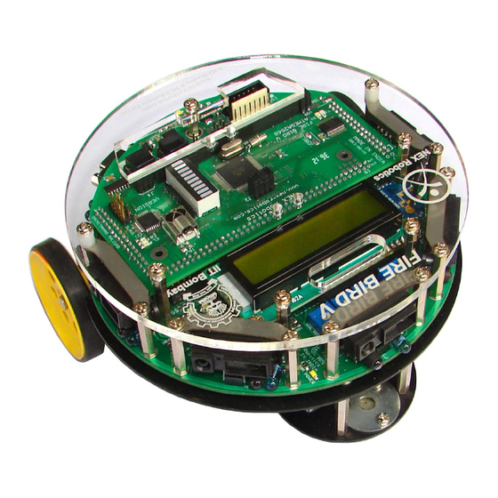
- Page 13 Fire Bird V robot has 6 important modules: 1. Power management 2. Sensing 3. Actuation (locomotion) 4. Other peripherals 5. Communication 6. Intelligence (microcontroller) Figure 3.1 Fire Bird V ATMEGA2560 robot © NEX Robotics Pvt. Ltd. and ERTS Lab, CSE, IIT Bombay, INDIA...
- Page 14 Fire Bird V ATMEGA2560 Hardware Manual 3.1 Connections Figure 3.2: Fire Bird V ATMEGA2560 robot bottom view Figure 3.3: ATMEGA2560 microcontroller adapter board © NEX Robotics Pvt. Ltd. and ERTS Lab, CSE, IIT Bombay, INDIA...
- Page 15 Fire Bird V ATMEGA2560 Hardware Manual Figure 3.4: Top view of the main board © NEX Robotics Pvt. Ltd. and ERTS Lab, CSE, IIT Bombay, INDIA...
- Page 16 Fire Bird V ATMEGA2560 Hardware Manual Figure 3.5: Bottom view of the main board Figure 3.6: Microcontroller adapter board socket connection numbers on the main board © NEX Robotics Pvt. Ltd. and ERTS Lab, CSE, IIT Bombay, INDIA...
- Page 17 In case the experiments are to be performed for an extended period, robot can also be powered by external auxiliary power supply. Figure 3.7: Power Switch Figure 3.8: Connecting the battery on the Fire Bird V main board © NEX Robotics Pvt. Ltd. and ERTS Lab, CSE, IIT Bombay, INDIA...
- Page 18 Robot is pre-loaded with a program to move robot in repeatedly in forward, backward, left and right directions. Refer to section 3.4 for battery charging. For running the robot on battery power or auxiliary power, refer to the section 3.5 and 3.6. © NEX Robotics Pvt. Ltd. and ERTS Lab, CSE, IIT Bombay, INDIA...
- Page 19 Power management block on the Fire Bird V performs following functions. 1. Battery voltage monitoring and Smart battery charging 2. Regulated supply for on-board payload 3. Battery current sensing* * Current sensing is an optional accessory. © NEX Robotics Pvt. Ltd. and ERTS Lab, CSE, IIT Bombay, INDIA...
- Page 20 Figure 3.9: Battery Connector on the main board Figure 3.10: Battery for Fire Bird V ATMEGA2560 Pin Number Function Battery Positive (VCC) Thermistor Battery Negative (GND) Table 3.1: Battery connections © NEX Robotics Pvt. Ltd. and ERTS Lab, CSE, IIT Bombay, INDIA...
- Page 21 8V to 11.3V depending on the battery's charging state and type of power source (battery / auxiliary power) used. This line can supply additional 500mA to the external load. Figure 3.11: Voltage regulators on the main board © NEX Robotics Pvt. Ltd. and ERTS Lab, CSE, IIT Bombay, INDIA...
-
Page 22: Current Sensing
8V, buzzer starts giving one long beep followed by 2 short beeps with delay of half second. At the same time red led marked in figure 3.14 starts flashing. © NEX Robotics Pvt. Ltd. and ERTS Lab, CSE, IIT Bombay, INDIA... -
Page 23: Battery Charging
Battery charge status is indicated by a buzzer, a red LED and a green LED shown in figure 3.14. Figure 3.13: Connection for battery charging Figure 3.14: Battery charging status indicator LEDs & Buzzer © NEX Robotics Pvt. Ltd. and ERTS Lab, CSE, IIT Bombay, INDIA... - Page 24 However the run time of the charged battery will be reduced significantly. © NEX Robotics Pvt. Ltd. and ERTS Lab, CSE, IIT Bombay, INDIA...
- Page 25 This is a very dangerous scenario where robot's battery charging circuit may get confused because of noise from motors and both battery and robot may get permanently damaged. © NEX Robotics Pvt. Ltd. and ERTS Lab, CSE, IIT Bombay, INDIA...
- Page 26 Do not connect auxiliary power while battery is connected to the robot. In such case, robot will either run on the battery power or on auxiliary power depending on the position of the switch. Robot can not be turned off in this scenario. © NEX Robotics Pvt. Ltd. and ERTS Lab, CSE, IIT Bombay, INDIA...
-
Page 27: Battery Maintenance
3.18. You can mount fuse of 2A to 10A rating on these pads as shown in the right side image of figure 3.16. Figure 3.16: Optional Fuse on the main board © NEX Robotics Pvt. Ltd. and ERTS Lab, CSE, IIT Bombay, INDIA... -
Page 28: Motion Control
Velocity control is done using Pulse Width Modulation (PWM). LEDs are connected at the input stage of the motor driver for quick interpretation of the motion commands. Figure 3.18: Motor Drivers © NEX Robotics Pvt. Ltd. and ERTS Lab, CSE, IIT Bombay, INDIA... - Page 29 Left motor 1 direction control Left motor 2 direction control Right motor 1 direction control Right motor 2 direction control Table 3.3: Pin functions for the motion control © NEX Robotics Pvt. Ltd. and ERTS Lab, CSE, IIT Bombay, INDIA...
- Page 30 We can observe all the commands given on the LEDs located at the top right side on the robot. Figure 3.20 shows the location and function of indicator LEDs related to motion control. Figure 3.20: Motion status LED indication on the Fire Bird V main board © NEX Robotics Pvt. Ltd. and ERTS Lab, CSE, IIT Bombay, INDIA...
- Page 31 Logic signals of pins 66 to 68 of the main board socket for interfacing external high power Interface Port2 motor drivers for C2 motor Table 3.5: Use of connectors of the motion control module © NEX Robotics Pvt. Ltd. and ERTS Lab, CSE, IIT Bombay, INDIA...
- Page 32 VCC, 5V System Position Encoder data Motor 2 Motor 1 Table 3.6: Motor connector port pin connections Figure 3.22: Schematic of the motion control module and the position encoder © NEX Robotics Pvt. Ltd. and ERTS Lab, CSE, IIT Bombay, INDIA...
- Page 33 Logic input 2 for Left motor (Left Output forward) Logic input 1 for Left motor (Left back) Output Table 3.7: Connections of the motor driver with the ATMEGA2560 microcontroller © NEX Robotics Pvt. Ltd. and ERTS Lab, CSE, IIT Bombay, INDIA...
- Page 34 IC sockets. You can interface high power motor drivers such as Hercules or Hercules lite from NEX Robotics which can drive motors up to 36V and 30Amps to the external motor interface ports. Location of L293D ICs is shown in figure 3.18 and External Motor Interface port 1 and External Motor Interface Port 2 in figure 3.21.
-
Page 35: Position Encoders
Output from the position encoder is cleaned using Schmitt trigger based inverter (not gate) IC CD40106. Figure 3.25: DC geared motors and position encoders © NEX Robotics Pvt. Ltd. and ERTS Lab, CSE, IIT Bombay, INDIA... - Page 36 External Interrupt for Interrupt switch on the CLK0/ICP3/INT7 microcontroller board, External Interrupt for the C1 Input / PE7 motor’s position encoder * Table 3.8: Pin Connection of the position encoder’s outputs © NEX Robotics Pvt. Ltd. and ERTS Lab, CSE, IIT Bombay, INDIA...
- Page 37 C1 motor's position encoder, ATMEGA2560 microcontroller will go in to boot mode. Figure 3.28 shows location of the pad P1 on the main board. Figure 3.28: Pad P1 open and with short © NEX Robotics Pvt. Ltd. and ERTS Lab, CSE, IIT Bombay, INDIA...
- Page 38 = Number of slots on the encoder disc / Number of wheel rotations of in 360 rotation of robot = 30 x 2.941 = 88.23 (approximately 88) Position Encoder Resolution in Degrees = 360 / 88 = 4.090 degrees per count © NEX Robotics Pvt. Ltd. and ERTS Lab, CSE, IIT Bombay, INDIA...
- Page 39 = Number of slots on the encoder disc / Number of wheel rotations of in 360 rotation of robot = 30 x 5.882 = 176.46 (approximately 176) Position Encoder Resolution in Degrees = 360 /176 = 2.045 degrees per count © NEX Robotics Pvt. Ltd. and ERTS Lab, CSE, IIT Bombay, INDIA...
- Page 40 In the blind spot region sensor gives incorrect readings. Table 3.9 gives information about sensing range and the blind spot distance for the particular sensor. Figure 3.29: Sharp Sensors mounted on Fire Bird V © NEX Robotics Pvt. Ltd. and ERTS Lab, CSE, IIT Bombay, INDIA...
- Page 41 10cm to 0cm GP2Y0A02 150cm to 20cm 20cm to 0cm Table 3.9: Sharp IR Range sensors coverage Figure 3.33: Distance Vs. Output voltage of GP2D120, GP2Y0A02YK and GP2Y0A02YK © NEX Robotics Pvt. Ltd. and ERTS Lab, CSE, IIT Bombay, INDIA...
- Page 42 Table 3.10: Connections of the Sharp IR range sensors and its power control MOSFETs with the ATMEGA2560 microcontroller * Sharp IR range sensor enabling and disabling is covered in section 3.10A © NEX Robotics Pvt. Ltd. and ERTS Lab, CSE, IIT Bombay, INDIA...
- Page 43 Same way White line sensors and IR proximity sensors can be switched ON and OFF, which can bee permanently turned ON by placing respective jumpers. Their switching circuits are discussed in their respective topics. © NEX Robotics Pvt. Ltd. and ERTS Lab, CSE, IIT Bombay, INDIA...
- Page 44 To avoid this small insulator foam is inserted between the sensor and the metal stripe which holds the sensor in place. © NEX Robotics Pvt. Ltd. and ERTS Lab, CSE, IIT Bombay, INDIA...
- Page 45 1 (5V) to the pin no. 34 of the main board. To enable these sensors permanently connect the IRP jumper on J1 of main board. For jumper location refer to figure 3.38. © NEX Robotics Pvt. Ltd. and ERTS Lab, CSE, IIT Bombay, INDIA...
- Page 46 IR LEDs. You can also remove effect of ambient light on the proximity detection by taking reading while IR LED is on and off and checking difference between the readings. © NEX Robotics Pvt. Ltd. and ERTS Lab, CSE, IIT Bombay, INDIA...
- Page 47 **For using Analog IR proximity (1, 2, 3 and 4) sensors short the jumper J2 on the microcontroller adapter board. For more details refer to section 3.19.6. To use JTAG via expansion slot of the microcontroller socket remove these jumpers. © NEX Robotics Pvt. Ltd. and ERTS Lab, CSE, IIT Bombay, INDIA...
- Page 48 Hence to do ISP you need to disconnect jumper J4 on the microcontroller adaptor board. To access data from the slave microcontroller ATMEGA8 over SPI bus Jumper J4 on the microcontroller socket needs to be connected. © NEX Robotics Pvt. Ltd. and ERTS Lab, CSE, IIT Bombay, INDIA...
- Page 49 Additional 4 potentiomenters can be readly soldered on the main board. Figure 3.42 shows all seven potentiomenters but robot is shipped with only 3 potentiomentrs for left, centre and right side white line sensor. © NEX Robotics Pvt. Ltd. and ERTS Lab, CSE, IIT Bombay, INDIA...
- Page 50 Figure 3.41a. White line sensor module on main board schematic Figure 3.41b. White line sensor PCB schematic Note: White line sensor number 4 t o7 uses ADC of the ATMEGA8 slave microcontroller. © NEX Robotics Pvt. Ltd. and ERTS Lab, CSE, IIT Bombay, INDIA...
- Page 51 White line sensor 3 (Right sensor) Data Out White line sensor 3 LED via potentiometer White line sensor 4 Data Out White line sensor 4 LED via potentiometer* © NEX Robotics Pvt. Ltd. and ERTS Lab, CSE, IIT Bombay, INDIA...
- Page 52 ADC input for white line sensor 6 PC3 (ADC3) ADC input for white line sensor 7/Servo pod Table 3.17 Connections of the IR Proximity sensors with the ATMEGA8 (slave microcontroller) © NEX Robotics Pvt. Ltd. and ERTS Lab, CSE, IIT Bombay, INDIA...
- Page 53 In case of red illumination which has very less infrared radiation even infrared black is still considered as black which makes red light as color of choice. © NEX Robotics Pvt. Ltd. and ERTS Lab, CSE, IIT Bombay, INDIA...
- Page 54 Figure below shows locations of the ultrasonic sensors. They are numbered as 1 to 5 from left to right in clockwise direction. Figure 3.44a: Five Ultrasonic Range Sensors on Fire Bird V © NEX Robotics Pvt. Ltd. and ERTS Lab, CSE, IIT Bombay, INDIA...
- Page 55 “TX” and “RX” of the sensors which comes before this sensor (in this case 1 and 2), so that trigger from microcontroller can reach the installed sensor. © NEX Robotics Pvt. Ltd. and ERTS Lab, CSE, IIT Bombay, INDIA...
- Page 56 FireBird V robot mainly uses EZ0 to EZ4 sensors from MaxBotix. All these sensors are available on NEX Robotics website. Other sensors from MaxBotix having compatible pin mapping can also be used instead of these sensors. For more details on compatibility, refer to the respective sensor’s datasheet.
- Page 57 It is good idea to solder them directly on main board and slight bend them upward. © NEX Robotics Pvt. Ltd. and ERTS Lab, CSE, IIT Bombay, INDIA...
- Page 58 0. Refer LCD datasheet provided in documentation CD for using Busy flag. Figure 3.45: LCD socket and other settings Figure 3.46: LCD socket pin connection © NEX Robotics Pvt. Ltd. and ERTS Lab, CSE, IIT Bombay, INDIA...
- Page 59 D4 to D7 (Data lines) Bidirectional data Bus 26 to 28 LED+, LED- Back light control ---- Table 3.18: LCD Pin mapping and functions Figure 3.48: LCD display schematics © NEX Robotics Pvt. Ltd. and ERTS Lab, CSE, IIT Bombay, INDIA...
- Page 60 LCD contrast control potentiometer. In order to save power LCD backlight can be turned off by removing LCD backlight jumper. LCD’s contrast can be adjusted by LCD contrast control potentiometer. © NEX Robotics Pvt. Ltd. and ERTS Lab, CSE, IIT Bombay, INDIA...
- Page 61 Buzzer is driven by BC548 transistor. Resistor 100K is used to keep transistor off, if the input pin is floating. Buzzer will get turned on if input voltage is greater than 0.65V. © NEX Robotics Pvt. Ltd. and ERTS Lab, CSE, IIT Bombay, INDIA...
- Page 62 Main board has SPI connector for adding accessories such as robotic arm, color sensor etc. Figure 3.52 shows its location on the main board and figure 3.52a shows its connections. Figure 3.52: SPI expansion port pins Figure 3.52a: SPI expansion port pins © NEX Robotics Pvt. Ltd. and ERTS Lab, CSE, IIT Bombay, INDIA...
-
Page 63: Serial Communication
Figure 3.54: Serial port connections with the main board socket Pin No. Description Main Board pin numbers Receiver Data (RXD) Pin 74 Transmit Data (TXD) Pin 75 Signal Ground (GND) Ground Table 3.19: Serial port pin out © NEX Robotics Pvt. Ltd. and ERTS Lab, CSE, IIT Bombay, INDIA... -
Page 64: Usb Communication
All its pins are connected to the microcontroller adapter board via main board's socket connector. Figure 3.55: USB port on the Fire Bird V main board Figure 3.55a: USB port connections with the main board socket © NEX Robotics Pvt. Ltd. and ERTS Lab, CSE, IIT Bombay, INDIA... - Page 65 For more information on this, refer to “Application Notes” folder which is located inside the “Manuals and Application notes” folder in the documentation © NEX Robotics Pvt. Ltd. and ERTS Lab, CSE, IIT Bombay, INDIA...
- Page 66 ATMEGA2560 microcontroller adapter board has two low drop voltage regulators: 1. “5V uC” supplies power to the microcontroller and its peripherals. 2. “5V servo” supplies power to the servo motor. Figure 3.59: Power Supply Circuit © NEX Robotics Pvt. Ltd. and ERTS Lab, CSE, IIT Bombay, INDIA...
- Page 67 • (10K + 3.3K) / 3.3K is a voltage divider formula • Figure 3.60: Battery Voltage Divider Bias Circuit Note: For 10 bit resolution replace 255 by 1024. © NEX Robotics Pvt. Ltd. and ERTS Lab, CSE, IIT Bombay, INDIA...
- Page 68 Important: Before using TSOP1738 insure that solder pad P1 on the main board is not shorted. For more information refer to section 3.9 and figure 3.28. © NEX Robotics Pvt. Ltd. and ERTS Lab, CSE, IIT Bombay, INDIA...
- Page 69 / tilt servo pod. It is a 8 pin 2560 relimate connector. Table 3.22 gives its pin connections. Fig 3.64: Servo Pod Sensor Socket Figure 3.65: Servo pod sensor connector pin mapping © NEX Robotics Pvt. Ltd. and ERTS Lab, CSE, IIT Bombay, INDIA...
- Page 70 In System Programming (ISP) to load firmware on the master and slave microcontroller via SPI port you need to remove all jumpers from J4 before attempting ISP. J4 is kept open as default setting. © NEX Robotics Pvt. Ltd. and ERTS Lab, CSE, IIT Bombay, INDIA...
- Page 71 ATMEGA8 microcontrollers. Note: To do In System Programming of ATMEGA2560 and ATMEGA8 microcontrollers jumper J4 must be absent. For more details refer to section 3.19.6 for the J4. © NEX Robotics Pvt. Ltd. and ERTS Lab, CSE, IIT Bombay, INDIA...
- Page 72 Refer to section 3.19.6 for correct jumper settings. Figure 3.68: FT232 Schematic Note: Using bootloader from NEX Robotics, Robot can be programmed directly via USB port without any need of external ISP programmer. How to use Bootloader GUI is covered in the software manual.
- Page 73 Figure 3.70: REF5050 Schematic Figure 3.71: Left- Jumper shorted to use 5V uC as A Ref. Right- REF5050 is installed and jumper shorted to use its 5V output as reference. © NEX Robotics Pvt. Ltd. and ERTS Lab, CSE, IIT Bombay, INDIA...
- Page 74 “5V servo supply” voltage regulator. Figure 3.73 shows correct orientation of the servo motor's connector. Figure: 3.73: Servo Connectors Schematic. Figure: 3.73a: Servo Connectors Schematic © NEX Robotics Pvt. Ltd. and ERTS Lab, CSE, IIT Bombay, INDIA...
- Page 75 Bargraph LED display is used for quick debugging purpose. It is connected to the PORTJ of the ATMEGA2560 microcontroller. To enable bargraph jumper J3 needs to be connected. For more details refer to the section 3.19.6. Figure 3.75: LED BAR GRAPH Schematic © NEX Robotics Pvt. Ltd. and ERTS Lab, CSE, IIT Bombay, INDIA...
- Page 76 SPI lines are connected with the jumper J4. For more details on the jumpers, refer to the section 3.19.6. Figure 3.76: ATMEGA8 SCHEMATIC Note: Firmware (ATMEGA8.hex ) for the ATMEGA8 microcontroller is located in the GUI and Related Firmware folder in the documentation CD. © NEX Robotics Pvt. Ltd. and ERTS Lab, CSE, IIT Bombay, INDIA...
- Page 77 Fire Bird V ATMEGA2560 Hardware Manual 3.19.15 ATMEGA2560 Microcontroller ATMEGA2560 is interfaced directly to most of the onboard peripherals. Its schematic is shown in the figure 3.78. Figure 3.78: ATMEGA2560 microcontroller schematic © NEX Robotics Pvt. Ltd. and ERTS Lab, CSE, IIT Bombay, INDIA...
-
Page 78: Pin Functionality
OC2A/PCINT4/PB4 Servo Pod GPIO OC1A/PCINT5/PB5 PWM for Servo motor 1. *** Output OC1B/PCINT6/PB6 PWM for Servo motor 2. *** Output OC0A/OC1C/PCINT7/PB7 PWM for Servo motor 3. *** Output © NEX Robotics Pvt. Ltd. and ERTS Lab, CSE, IIT Bombay, INDIA... - Page 79 Red LEDs of white line sensor enable/disable. ******* PG2/ALE Output Turns off these sensors when output is logic 1 PA7 C2-2 Logic input 2 for C2 motor drive Output © NEX Robotics Pvt. Ltd. and ERTS Lab, CSE, IIT Bombay, INDIA...
- Page 80 * Not used pins are by default initialized to input and kept floating. These pins are available on the expansion slot of the ATMEGA2560 microcontroller adapter board. Some pins are especially reserved for servo motor interfacing for the Fire Bird V Hexapod robot. © NEX Robotics Pvt. Ltd. and ERTS Lab, CSE, IIT Bombay, INDIA...
- Page 81 P1 near CD40106 Schmitt trigger inverter buffer to avoid its wire ANDing with the interrupt switch. Refer section 3.9 and 3.19.3 for details. ********* Refer the errata section for more details, where modification required for using PH4 port pin of microcontroller. © NEX Robotics Pvt. Ltd. and ERTS Lab, CSE, IIT Bombay, INDIA...
- Page 82 SPI interface to ATMEGA8. J4 needs to be disconnected before doing ISP. To communicate with ATMEGA8 jumper J4 needs to be in place. For more details refer to section 3.19.6 J4. © NEX Robotics Pvt. Ltd. and ERTS Lab, CSE, IIT Bombay, INDIA...
- Page 83 T4 / PH7 / GPIO (uC pin 27) ICP5 / PL1 / GPIO (uC pin 36) ICP4 / PL0 / GPIO (uC pin 35), Also connected to RSSI pin of XBee module © NEX Robotics Pvt. Ltd. and ERTS Lab, CSE, IIT Bombay, INDIA...
- Page 84 LED display. While using these pins as UART 3, jumper J3 must be removed to disable bargraph LED display in order to avoid loading on the TXD and RXD lines of the device which is connected with the ATMEGA2560 microcontroller. © NEX Robotics Pvt. Ltd. and ERTS Lab, CSE, IIT Bombay, INDIA...
- Page 85 To enable USB communication, set Jumper 1 as shown in the figure 6.2 USB Data- Pin 16 of FT232 USB to serial converter going to UART 2 of ATMEGA2560 © NEX Robotics Pvt. Ltd. and ERTS Lab, CSE, IIT Bombay, INDIA...
- Page 86 Analog output of white line sensor 5 White Line 6 ATMEGA8 ADC2 Analog output of white line sensor 6 White Line 7 ATMEGA8 ADC3 Analog output of white line sensor 7 © NEX Robotics Pvt. Ltd. and ERTS Lab, CSE, IIT Bombay, INDIA...
- Page 87 Table 4.4: ATMEGA2560 Microcontroller adapter board socket connections with the main board Note: * CS will give output only if ACS712 hall effect current sensor is soldered on the main board ** refer errata section of this manual © NEX Robotics Pvt. Ltd. and ERTS Lab, CSE, IIT Bombay, INDIA...
- Page 88 Fire Bird V ATMEGA2560 Hardware Manual 5. Upgrading Robot’s Hardware In this chapter mounting of various modules of the robot are covered in pictorial way. Figure 5.1: Fire Bird V main board © NEX Robotics Pvt. Ltd. and ERTS Lab, CSE, IIT Bombay, INDIA...
- Page 89 XBee USB wireless module and X-CTU software. For more details refer to Application notes. 5.2 Setting correct jumper settings on the main board Figure 5.3: Set jumpers as per the requirements (for more details refer to chapter 3) © NEX Robotics Pvt. Ltd. and ERTS Lab, CSE, IIT Bombay, INDIA...
- Page 90 5.3 LCD mounting Figure 5.4: LCD mounting • Be careful while inserting LCD connector pins into the socket on the main board. Screw in the LCD firmly on the studs. © NEX Robotics Pvt. Ltd. and ERTS Lab, CSE, IIT Bombay, INDIA...
- Page 91 Fire Bird V ATMEGA2560 Hardware Manual 5.4 Microcontroller adapter board mounting Figure 5.5: ATMEGA2560 (AVR), P89V51RD2 (8051) and LPC2148 ARM7 microcontroller adapter boards for Fire Bird V © NEX Robotics Pvt. Ltd. and ERTS Lab, CSE, IIT Bombay, INDIA...
- Page 92 Do not apply unnecessary pressure onto the PCB while inserting into the connectors on • the main board. Check for any bent pins before inserting the PCB. Mount 3 screws on the microcontroller board. © NEX Robotics Pvt. Ltd. and ERTS Lab, CSE, IIT Bombay, INDIA...
- Page 93 5.9, area highlighted with the red border shows the mounted studs from the Sharp IR range sensor mounting kit. Figure 5.9: Mount 20mm studs from the Sharp sensor mounting kit © NEX Robotics Pvt. Ltd. and ERTS Lab, CSE, IIT Bombay, INDIA...
- Page 94 Do not apply extreme pressure while pressing down the sharp sensors to fit into the • socket. Make sure that you remove yellow paper before mounting the metal plate on the Sharp IR • range sensor. © NEX Robotics Pvt. Ltd. and ERTS Lab, CSE, IIT Bombay, INDIA...
- Page 95 Fire Bird V ATMEGA2560 Hardware Manual 5.6 Mount top Acrylic plate on the robot Figure 5.12: Install top acrylic plate © NEX Robotics Pvt. Ltd. and ERTS Lab, CSE, IIT Bombay, INDIA...
- Page 96 Section 6.2 and 6.3 covers robot control using PC’s USB port and XBee wireless module. Important: While using “Numerical Pad” of the key board, make sure that “Num Lock” is on. © NEX Robotics Pvt. Ltd. and ERTS Lab, CSE, IIT Bombay, INDIA...
- Page 97 “13A_Serial_Communication.hex” on the robot which is located in the “Experiments” folder in the documentation CD. For robot control over serial port we use Terminal software from NEX Robotics. It is located in the “Software” folder in the documentation CD. Installation and the use of the terminal software from NEX Robotics is covered in the section 6.7.
- Page 98 For driver installation process refer to section 6.5. For robot control over serial port we use Terminal software from NEX Robotics. It is located in the “Software” folder in the documentation CD. Installation and the use of the terminal software from NEX Robotics is covered in the section 6.7.
- Page 99 “Software and Drivers \ CDM 2.06.00 WHQL Certified” folder. For driver installation process refer to section 6.5. For robot control over serial port we use Terminal software from NEX Robotics. It is located in the “Software” folder in the documentation CD. Installation and the use of the terminal software from NEX Robotics is covered in the section 6.7.
- Page 100 On connecting the device “Found New Hardware” message will appear in the task bar tray and the following window opens. Figure 6.4 Step 4: Check on the radio button “No, not this time” and then click on the next button. © NEX Robotics Pvt. Ltd. and ERTS Lab, CSE, IIT Bombay, INDIA...
- Page 101 Fire Bird V ATMEGA2560 Hardware Manual Figure 6.5 The following window will appear. Figure 6.6 Select the second option manually to install the drivers and click on next button. © NEX Robotics Pvt. Ltd. and ERTS Lab, CSE, IIT Bombay, INDIA...
- Page 102 Now check the second option and set the location of folder containing drivers E.g.(C:\CDM 2.06.00 WHQL Certified). Figure 6.7 Step 6: On clicking next driver installation will begin. Figure 6.8 © NEX Robotics Pvt. Ltd. and ERTS Lab, CSE, IIT Bombay, INDIA...
- Page 103 After installation of FT232 USB UART software, PC may ask for USB serial port software. To install this software follow steps 1 to 7 of USB serial converter software installation. © NEX Robotics Pvt. Ltd. and ERTS Lab, CSE, IIT Bombay, INDIA...
- Page 104 Right Click My Computer and click on properties. System properties window will appear. Figure 6.10 Step 2: Click on the Device manager in the Hardware tab. Figure 6.11 © NEX Robotics Pvt. Ltd. and ERTS Lab, CSE, IIT Bombay, INDIA...
- Page 105 You can change the port number by right clicking on “USB serial Port” and select properties. Figure 6.13 In the Port settings tab click on the Advanced button, the following window will appear. © NEX Robotics Pvt. Ltd. and ERTS Lab, CSE, IIT Bombay, INDIA...
- Page 106 6.7 Use of Terminal software from NEX Robotics for Robot control Terminal is easy to use free software for serial communication written by NEX Robotics. It is located in the “Software and Drivers” folder in the documentation CD. In the following example we will be using Serial communication protocol covered in the section 6.
- Page 107 Fire Bird V ATMEGA2560 Hardware Manual Figure 6.15 Figure 6.16 © NEX Robotics Pvt. Ltd. and ERTS Lab, CSE, IIT Bombay, INDIA...
- Page 108 Connect any device which is to be used to USB / serial port. Install its driver. Go to Start menu and click on the Serial Terminal. Figure 6.17 Terminal software will open. Figure 6.18 © NEX Robotics Pvt. Ltd. and ERTS Lab, CSE, IIT Bombay, INDIA...
- Page 109 Turn on the robot. Connect the Serial / USB wire or XBee wireless link between robot and PC Use number keys of the key pad to control the robot. For control commands refer to table 6.1. Figure 6.20 © NEX Robotics Pvt. Ltd. and ERTS Lab, CSE, IIT Bombay, INDIA...
- Page 110 Received data is displayed in the top window. In all three application examples mentioned in section 6.2, 6.3 and 6.4 robot sends back echo of the received data apart from executing the motion commands. © NEX Robotics Pvt. Ltd. and ERTS Lab, CSE, IIT Bombay, INDIA...
- Page 111 Step 3: Browse the location where set up will install or set the default location and click Next Button to start the installation. Step 4: When installation is successfully completed, Click Close to exit. © NEX Robotics Pvt. Ltd. and ERTS Lab, CSE, IIT Bombay, INDIA...
-
Page 112: Using Gui
GUI will open. Figure 7.2: Selecting correct com port Step 2: Connect Robot with the PC using serial cable / NEX Robotics USB to serial converter or with the XBee wireless module. For connections refer to section 6.2 to 6.6. - Page 113 Step 3: If serial port is used then select COM Port as 1. If USB to serial converter module from NEX Robotics or USB ZigBee wireless module is used then GUI automatically identifies the COM port number. To manually identify the COM port, refer to section 6.6. Select the correct COM port number and click on connect.
- Page 114 Fire Bird V ATMEGA2560 Hardware Manual Step 4: If you have Wireless camera pod from NEX Robotics and USB TV Tuner card then you can also see the video on the GUI. For more information on the installation and usage process, refer to documentation of the wireless camera pod.
- Page 115 7.1, 7.2 and 7.3. Only difference is that instead of USB to serial converter, NEX Robotics wireless XBee USB module needs to be connected to the PC and XBee wireless module needs to be installed on the robot. Make sure that XBee module on the robot and XBee module on the XBee USB module are configured at 115200bps.
- Page 116 Note: It is very important that you send the byte containing command 1 first and then send the byte containing command 2 for proper operation. The same rule is applicable for commands 3 and 4. © NEX Robotics Pvt. Ltd. and ERTS Lab, CSE, IIT Bombay, INDIA...
- Page 117 Load the upper nibble ‘6’ of the right motor speed into the robot and execute the command Step8: Delay of at least 3 milliseconds Step9: 0x52 move backward Step10: Delay of at least 3 milliseconds before loading next command © NEX Robotics Pvt. Ltd. and ERTS Lab, CSE, IIT Bombay, INDIA...
- Page 118 The Robot will return an 8 bit analog value of the IR Proximity sensor 5 IR Proximity sensor 6 The Robot will return an 8 bit analog value of the IR Proximity sensor 6 © NEX Robotics Pvt. Ltd. and ERTS Lab, CSE, IIT Bombay, INDIA...
- Page 119 Note: To get an actual pulse count, combine the lower byte and upper byte to get a 16 bit value. For more information on the position encoder resolution refer to the section 3.9. © NEX Robotics Pvt. Ltd. and ERTS Lab, CSE, IIT Bombay, INDIA...
- Page 120 Upper nibble = 3 hex Combining these nibbles with the commands: Step1: send 0x8D through the serial port Step2: delay by 3 milliseconds Step3: send 0x93 through the serial port © NEX Robotics Pvt. Ltd. and ERTS Lab, CSE, IIT Bombay, INDIA...
- Page 121 2 places in figure (A) and solder the wire as shown in figure(B). Figure(A) Figure(B) Important: It is also recommended to put some glue on both solder point, where you soldered the wire to give the strengthen the soldering point. © NEX Robotics Pvt. Ltd. and ERTS Lab, CSE, IIT Bombay, INDIA...
Need help?
Do you have a question about the FIREBIRD V ATMEGA 2560 and is the answer not in the manual?
Questions and answers