Table of Contents
Advertisement
Quick Links
OPERATOR'S MANUAL
MAGNETIC BOX AND PAN BRAKE
MODEL: BB-9616M
Baileigh Industrial Holdings LLC
P.O. Box 531
Manitowoc, WI 54221-0531
Phone: 920.684.4990
Fax: 920.684.3944
sales@baileigh.com
REPRODUCTION OF THIS MANUAL IN ANY FORM WITHOUT WRITTEN APPROVAL OF BAILEIGH INDUSTRIAL
HOLDINGS LLC IS PROHIBITED. Baileigh Industrial Holdings LLC, Inc. does not assume and hereby disclaims any
liability for any damage or loss caused by an omission or error in this Operator's Manual, resulting from accident,
negligence, or other occurrence.
Rev. 02/2020
© 2020 Baileigh Industrial Holdings LLC
Advertisement
Table of Contents

Related Manuals for Baileigh Industrial 1000568


Summary of Contents for Baileigh Industrial 1000568
- Page 1 REPRODUCTION OF THIS MANUAL IN ANY FORM WITHOUT WRITTEN APPROVAL OF BAILEIGH INDUSTRIAL HOLDINGS LLC IS PROHIBITED. Baileigh Industrial Holdings LLC, Inc. does not assume and hereby disclaims any liability for any damage or loss caused by an omission or error in this Operator’s Manual, resulting from accident, negligence, or other occurrence.
-
Page 2: Table Of Contents
Table of Contents THANK YOU & WARRANTY ..................1 INTRODUCTION ......................3 GENERAL NOTES ......................3 SAFETY INSTRUCTIONS ....................4 SAFETY PRECAUTIONS ....................6 Dear Valued Customer: ....................6 TECHNICAL SPECIFICATIONS ..................8 TECHNICAL SUPPORT ....................8 UNPACKING AND CHECKING CONTENTS ..............9 TRANSPORTING AND LIFTING .................. -
Page 3: Thank You & Warranty
THANK YOU & WARRANTY Thank you for your purchase of a machine from Baileigh Industrial Holdings LLC. We hope that you find it productive and useful to you for a long time to come. Inspection & Acceptance. Buyer shall inspect all Goods within ten (10) days after receipt thereof. Buyer’s payment shall constitute final acceptance of the Goods and shall act as a waiver of the Buyer’s rights to inspect or... - Page 4 We apologize for any discrepancies that may occur. Baileigh Industrial Holdings LLC reserves the right to make any and all changes deemed necessary in the course of business including but not limited to pricing, product specifications, quantities, and product availability.
-
Page 5: Introduction
INTRODUCTION The quality and reliability of the components assembled on a Baileigh Industrial Holdings LLC machine guarantee near perfect functioning, free from problems, even under the most demanding working conditions. However, if a situation arises, refer to the manual first. If a solution cannot be found, contact the distributor where you purchased our product. -
Page 6: Safety Instructions
IMPORTANT PLEASE READ THIS OPERATORS MANUAL CAREFULLY It contains important safety information, instructions, and necessary operating procedures. The continual observance of these procedures will help increase your production and extend the life of the equipment. SAFETY INSTRUCTIONS LEARN TO RECOGNIZE SAFETY INFORMATION This is the safety alert symbol. - Page 7 SAVE THESE INSTRUCTIONS. Refer to them often and use them to instruct others. PROTECT EYES Wear safety glasses or suitable eye protection when working on or around machinery. BEWARE OF CRUSH HAZARD Placing fingers or hands between the clamping leaf and the magnetic bed could cause serious personal injury.
-
Page 8: Safety Precautions
SAFETY PRECAUTIONS Metal working can be dangerous if safe and proper operating procedures are not followed. As with all machinery, there are certain hazards involved with the operation of the product. Using the machine with respect and caution will considerably lessen the possibility of personal injury. However, if normal safety precautions are overlooked or ignored, personal injury to the operator may result. - Page 9 7. Dressing material edges. Always chamfer and deburr all sharp edges. 8. Do not force tool. Your machine will do a better and safer job if used as intended. DO NOT use inappropriate attachments in an attempt to exceed the machines rated capacity. 9.
-
Page 10: Technical Specifications
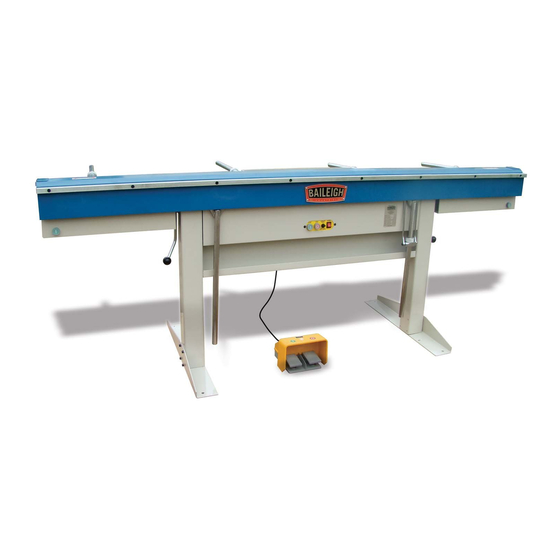
TECHNICAL SPECIFICATIONS 96” (2438mm) Bend Length Bend Material Thickness 16ga. (1.51mm) mild steel* Bending Leaf Extension Removed 20ga. (0.91mm) stainless steel** Bend Material Thickness 18ga. (1.21mm) mild steel* Bending Leaf Extension Installed 21ga. (0.83mm) stainless steel** 0 – 180 degrees Bend Angle Box Depth Unlimited... -
Page 11: Unpacking And Checking Contents
UNPACKING AND CHECKING CONTENTS Your Baileigh machine is shipped complete. Separate all parts from the packing material and check each item carefully. Make certain all items are accounted for before discarding any packing material. WARNING: SUFFOCATION HAZARD! Immediately discard any plastic bags and packing materials to eliminate choking and suffocation hazards to children and animals. - Page 13 Item Description Qty. Body and Pedestal Tool Tray Back Stop Collars Back Stop Bars Clamp Bar Left Foot Right Foot Bag of Hardware Foot Switch...
-
Page 14: Transporting And Lifting
TRANSPORTING AND LIFTING NOTICE: Lifting and carrying operations should be carried out by skilled workers, such as a truck operator, crane operator, etc. If a crane is used to lift the machine, attach the lifting chain carefully, making sure the machine is well balanced. Follow these guidelines when lifting with truck or trolley: •... -
Page 15: Installation
INSTALLATION IMPORTANT: Consider the following when looking for a suitable location to place the machine: • Overall weight of the machine. • Weight of material being processed. • Sizes of material to be processed through the machine. • Space needed for auxiliary stands, work tables, or other machinery. •... -
Page 16: Overall Dimensions
OVERALL DIMENSIONS... -
Page 17: Assembly And Set Up
ASSEMBLY AND SET UP WARNING: For your own safety, DO NOT connect the machine to the power source until the machine is completely assembled and you read and understand the entire instruction manual. Attaching the Legs 1. Use slings to remove the magnet body from the crate. Rest the body on wooden blocks. -
Page 18: Removing And Installing The Bending Extension Bar
Footswitch 1. Unstrap and straighten out the footswitch cable. 2. Grasp the connector end and plug into the receptacle at the back of the machine. 3. Tighten the connector sleeve. figure 5 Removing and Installing the Bending Extension Bar Note: The bending extension is typically on the bending leaf. -
Page 19: Electrical
220VAC ±5% (209VAC to 231VAC). Failure to comply will damage the machine and void the warranty. If needed, contact Baileigh Industrial at 920-684-4990 to purchase a Buck Boost transformer. The service personal will be able to assist in placing the order for the transformer or provide specifications so that you will be able to obtain the proper transformer for your application. - Page 20 WARNING: In all cases, make certain the receptacle in question is properly grounded. If you are not sure, have a qualified electrician check the receptacle • Improper connection of the equipment-grounding conductor can result in risk of electric shock. The conductor with insulation having an outer surface that is green with or without yellow stripes is the equipment-grounding conductor.
-
Page 21: Operation
OPERATION CAUTION: Always wear proper eye protection with side shields, safety footwear, and leather gloves to protect from burrs and sharp edges. When handling large heavy materials make sure they are properly supported. Keep hands and fingers clear of the clamping beam. Stand off to the side of the machine to avoid getting hit with the bending apron as it comes up to bend. - Page 22 5. If using a full length clamping bar, use the lift handles (A) to raise the clamping bar and then position the piece part under the clamp bar. Use the backstop if needed. IMPORTANT: NEVER activate the magnetic circuit with the clamping bar raised. The bar will snap down possible causing injury and or damaging the bar, the magnet table, or the material.
- Page 23 Important: Each time the machine switches OFF, a short pulse of reverse current is sent through the electromagnet to demagnetize it as well as the piece part. The timer is set to 2-3 seconds to help collapse the magnetic field. 13.
-
Page 24: Magnetism Notes
Magnetism Notes Heat will reduce the strength of magnetic field. This is important to know when using the magnetic brake for long periods of time. If is recommended to keep the amount of time that the magnetic coils are energized as short as possible. When the coils of the magnet are energized, the electrical current flowing through the coils creates heat. -
Page 25: Bending Allowance
BENDING ALLOWANCE In order to bend sheet metal accurately, you will need to consider the total length of each bend. This is referred to as bend allowance. Subtract the bend allowance from the sum of the outside dimensions of the piece part to obtain the actual overall length or width of the piece. Because of differences in sheet metal hardness, and whether the bend is made with the grain or against it, exact allowances must sometimes be made by trial and error. -
Page 26: Bend Configurations
BEND CONFIGURATIONS Return Bends Rolled Edge Closed Channel Stiffening Rib Angle Bend Fins BENDING EXAMPLES Folding Over a Lip The thickness, width, and length of material are factors to consider when folding a lip. DO NOT exceed 20ga. (.035”) for material thickness. 1. - Page 27 Rolling an Edge Use a piece of solid steel round or a pipe to accomplish this. 1. Position the clamping bar and the round bar as shown in (fig. 14) to ensure that the piece part is positioned correctly. Energize the electromagnet. figure 14 2.
- Page 28 Forming Pans With Slotted Clamp Bar The slotted clamping bar works great for making shallow pans and trays. The entire clamp bar lifts automatically for easy insertion and removal of the piece part. 1. Fold two opposite sides and the corner tabs with the slotted clamp bar. (The slots will NOT affect these bends.) 2.
-
Page 29: Lubrication And Maintenance
LUBRICATION AND MAINTENANCE WARNING: Make sure the electrical disconnect is OFF before working on the machine. Maintenance should be performed on a regular basis by qualified personnel. Always follow proper safety precautions when working on or around any machinery. • Check daily for any unsafe conditions and fix immediately. •... -
Page 30: Checking Machine Accuracy
Checking Machine Accuracy To achieve and maintain accurate bends on the Baileigh BB-9616M magnetic brake, the working surface of the bending beam and the bending edge of the clamp bar need to be straight. Both of these surfaces must also be parallel to each other. This can be checked periodically with a precision straight edge. -
Page 31: Parts Diagram
PARTS DIAGRAM... - Page 32 PARTS IDENTIFICATION LIST Item Description Qty. Right feet Left feet Screw M8x16 Right stand Right Shield Left Shield Electrical box Material box Left stand Right folding bar Left handle Rubber washer Back gauge Limited block Screw M8x20 Magnetic working table Bending board Bending board –...
- Page 33 Item Description Qty. Connect bar Pin shaft Shaft washer 10 Connect bar Cover Screw M6x16 Nut M6 Fixed nut Shaft washer 18 Key 6x20 Bolt M6x35 Cover 18x20x20 Stand Bolt M8x25 Connect shaft Handle ball Right handle Screw M8x16 Folding board Folding board strip Screw M8x20 Screw M8x20...
- Page 34 Item Description Qty. Graduated scale Left folding bar Screw M8x20 Connect bar Screw M8x6 Block Screw M8x20 Shaft Cover Screw M8x20 Stand Screw M8x16 Connect board Screw M8x30 Screw M8x20...
-
Page 35: Electrical Components
ELECTRICAL COMPONENTS Shown with cover panel removed Magnet Coil Resistance BB-9616M Magnet Coil Resistance Wires Reading 22 Ω 20 and 22 >200MΩ 20 and PE >200MΩ 22 and PE • Machine must be disconnected from the power supply. • Wires 20 and 22 must be removed the terminal strip. -
Page 36: Electrical Schematic
ELECTRICAL SCHEMATIC Magnet Control Board KS50 CBB61A 1.5W 450V 1.5uf CBB22 104J 10K? 400V DC450V 470uf 19-25VDC 0VDC 0VDC 210-230VDC KPBC2 KPBC1 220V Stop Pedal Start Pedal... -
Page 37: Electrical Components
Electrical Components Red Stop Push Button - NC Contact Contactor, CU-16, Primary coil activation circuit. Creates light clamping pressure. Contactor, CU-16, Primary coil activation circuit. Creates full clamping pressure. Control Board, Holds components C1, C2, C3, C4, D1, KS50, R1, and Control Board R2. -
Page 38: Troubleshooting
TROUBLESHOOTING WARNING: Make sure the electrical disconnect is OFF before working on the machine. FAULT PROBABLE CAUSE REMEDY Machine is not plugged in to a Have qualified electrician check live circuit circuit. Bending leaf lifted before start Return bending leaf to lower button is pressed position and press start button Bending leaf micro-switch out of... - Page 39 Full Clamping Not Operating If you are not achieving a full clamp, the angle micro switch may not be fully actuated. To check that the angle micro switch is being fully actuated. • The micro switch can be found on the electrical panel located at the end of the square brass section.
- Page 40 BAILEIGH INDUSTRIAL HOLDINGS LLC 1625 D , WI 54220 UFEK RIVE ANITOWOC : 920. 684. 4990 F : 920. 684. 3944 HONE www.baileigh.com BAILEIGH INDUSTRIAL HOLDINGS LTD. U WIFT OINT WIFT ALLEY NDUSTRIAL STATE UGBY , CV21 1QH U IDLANDS...