Table of Contents
Advertisement
Quick Links
ADS1282EVM and ADS1282EVM-PDK User's Guide
This user's guide describes the characteristics, operation, and use of the ADS1282EVM, both by itself and
as part of the ADS1282EVM-PDK. This evaluation model (EVM) is an evaluation board for the ADS1282,
a high-performance, 32-bit multi-channel, delta-sigma analog-to-digital converter (ADC). The EVM allows
evaluation of all aspects of the ADS1282. Complete circuit descriptions, schematic diagrams, and bills of
material are included in this document.
The following related documents are available for download through the Texas Instruments web site at
http://www.ti.com.
Device
ADS1282
REF5025
REF5050
OPA2350
OPA1632
PCA9535
ADCPro is a trademark of Texas Instruments.
SPI is a trademark of Motorola Inc.
2
I
C is a trademark of NXP Semiconductors.
NI-VISA is a trademark of National Instruments.
All other trademarks are the property of their respective owners.
SBAU144C – March 2009 – Revised May 2011
Submit Documentation Feedback
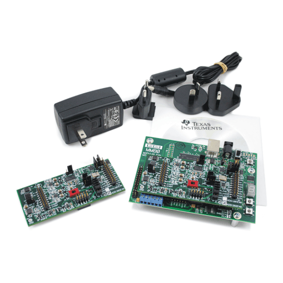
ADS1282EVM (Left) and ADS1282EVM-PDK (Right)
EVM-Compatible Device Data Sheets
Literature Number
SBAS418E
SBOS410C
SBOS410C
SBOS099C
SBOS286A
SCPS129H
Copyright © 2009–2011, Texas Instruments Incorporated
SBAU144C – March 2009 – Revised May 2011
Device
Literature Number
SN74LVC2G157
SCES207K
SN74LVC1G07
SCES296W
SN74AHCT1G04
SCLS319N
TPS79225
SLVS337B
TPS72325
SLVS346B
ADS1282EVM and ADS1282EVM-PDK User's Guide
User's Guide
1
Advertisement
Table of Contents

Related Manuals for Texas Instruments ADS1282EVM


Summary of Contents for Texas Instruments ADS1282EVM
- Page 1 ADS1282EVM and ADS1282EVM-PDK User's Guide ADS1282EVM (Left) and ADS1282EVM-PDK (Right) This user's guide describes the characteristics, operation, and use of the ADS1282EVM, both by itself and as part of the ADS1282EVM-PDK. This evaluation model (EVM) is an evaluation board for the ADS1282, a high-performance, 32-bit multi-channel, delta-sigma analog-to-digital converter (ADC).
-
Page 2: Table Of Contents
J6: Analog Interface Pinout ....................J5: Serial Interface Pins ..................J3 Configuration: Power-Supply Input ..................ADS1282EVM Bill of Materials SBAU144C – March 2009 – Revised May 2011 ADS1282EVM and ADS1282EVM-PDK User's Guide Submit Documentation Feedback Copyright © 2009–2011, Texas Instruments Incorporated... -
Page 3: Evm Overview
The MMB0 motherboard allows the ADS1282EVM to be connected to the computer via an available USB port. This manual shows how to use the MMB0 as part of the ADS1282EVM-PDK, but does not provide technical details about the MMB0 itself. -
Page 4: Digital Interface
Digital Interface www.ti.com The input pins on the ADS1282EVM are directly connected to the part, with no filtering or protection. It is important that appropriate caution is taken when handling the pins. Table 1 summarizes the pinouts for analog interface J6. -
Page 5: Power Supplies
U10 and U13 in bipolar mode. Jumpers must be properly placed across J7.1 and J7.2 as well as J7.3 and J7.4 to properly power the ADS1282 (shown in Figure Figure 1. Connectors for J7 SBAU144C – March 2009 – Revised May 2011 ADS1282EVM and ADS1282EVM-PDK User's Guide Submit Documentation Feedback Copyright © 2009–2011, Texas Instruments Incorporated... -
Page 6: Voltage Reference
TOUT pin (J5.17). Usage in PDK If using the ADS1282EVM as part of the ADS1282EVM-PDK, the J3 jumper should be set to the DVDD position. Using the onboard 4.096MHz crystal oscillator allows the the ADS1282EVM-PDK software to recognize the EVM using the software provided. -
Page 7: Evm Operation
Figure 4. ADS1282EVM Default Jumper Locations There is only one switch, S1, located on the ADS1282EVM; it is used to set the reference voltage (V The default position is to the left, indicating that the EVM is to use the onboard reference voltage. -
Page 8: Ads1282Evm-Pdk Kit Operation
CD). Double-click the file to run it; then follow the instructions shown. You can also use the ADCPro Update Check feature to check for newer versions of the ADS1282EVM-PDK plug-in, once you have installed one version of it. -
Page 9: Mmb0 Initial Setup
• Set the Boot Mode switch to USB. • Set jumper J4 low to indicate that the EVM board is an ADS1282EVM. Figure 5. MMB0 Initial Setup SBAU144C – March 2009 – Revised May 2011 ADS1282EVM and ADS1282EVM-PDK User's Guide Submit Documentation Feedback Copyright ©... -
Page 10: Connecting Ads1282Evm To Mmb0
The MMB0 is a Modular EVM System motherboard. It is designed around the TMS320VC5507, a DSP with an onboard USB interface from Texas Instruments. The MMB0 also has 16MB of SDRAM installed. The MMB0 is not sold as a DSP development board, and it is not available separately. TI cannot offer support for the MMB0 except as part of an EVM kit. -
Page 11: Using The +6V Wall Supply For +5V
Connecting the Power Supply The ADS1282EVM-PDK requires both a +5V supply and a external supply (±10V to ±15V) to operate. The +5V supply can be provided by either the +6V wall supply (included with the EVM-PDK) or an additional external supply. -
Page 12: Using A External Supply For +5V
J14. It is not necessary to connect a +5V dc supply voltage to the +5VA terminal on J14 if the +5V/+5VA position on J13 is shorted. SBAU144C – March 2009 – Revised May 2011 ADS1282EVM and ADS1282EVM-PDK User's Guide Submit Documentation Feedback Copyright © 2009–2011, Texas Instruments Incorporated... -
Page 13: Running The Software And Completing Driver Installation
Note: The software is continually under development. These instructions and screen images are current at the time of this writing, but may not exactly match future releases. The program for evaluating the ADS1282EVM-PDK is called ADCPro. This program uses plug-ins to communicate with the EVM. The ADS1282EVM-PDK plug-in is included in the ADS1282EVM-PDK package. -
Page 14: Ni-Visa Driver Installation Prompt
Running the Software and Completing Driver Installation www.ti.com Figure 10. NI-VISA Driver Installation Prompt Figure 11. NI-VISA Driver Installing SBAU144C – March 2009 – Revised May 2011 ADS1282EVM and ADS1282EVM-PDK User's Guide Submit Documentation Feedback Copyright © 2009–2011, Texas Instruments Incorporated... -
Page 15: Ni-Visa Driver Complete Installation
Device Manager and locating the hardware as shown in Figure Figure 13. NI-VISA Driver Verification Using Device Manager SBAU144C – March 2009 – Revised May 2011 ADS1282EVM and ADS1282EVM-PDK User's Guide Submit Documentation Feedback Copyright © 2009–2011, Texas Instruments Incorporated... -
Page 16: Adcpro Software Start-Up Display Window
Step 1. Start the software by selecting ADCPro from the Windows Start menu. The screen in Figure 14 appears. Figure 14. ADCPro Software Start-up Display Window SBAU144C – March 2009 – Revised May 2011 ADS1282EVM and ADS1282EVM-PDK User's Guide Submit Documentation Feedback Copyright © 2009–2011, Texas Instruments Incorporated... -
Page 17: Ads1282Evm-Pdk Plug-In Display Window
Figure 15. ADS1282EVM-PDK Plug-In Display Window Step 2. The ADS1282EVM-PDK plug-in window has a status area at the top of the screen. When the plug-in is first loaded, the plug-in searches for the board. You will see a series of messages in the status area indicating this action. -
Page 18: Install New Driver Wizard, Screen 1
Running the Software and Completing Driver Installation www.ti.com Figure 16. Install New Driver Wizard, Screen 1 Figure 17. Install New Driver Wizard, Screen 2 SBAU144C – March 2009 – Revised May 2011 ADS1282EVM and ADS1282EVM-PDK User's Guide Submit Documentation Feedback Copyright © 2009–2011, Texas Instruments Incorporated... -
Page 19: Install New Driver Wizard, Screen 3
Running the Software and Completing Driver Installation www.ti.com Figure 18. Install New Driver Wizard, Screen 3 Figure 19. Install New Driver Wizard, Screen 4 SBAU144C – March 2009 – Revised May 2011 ADS1282EVM and ADS1282EVM-PDK User's Guide Submit Documentation Feedback Copyright © 2009–2011, Texas Instruments Incorporated... -
Page 20: Install New Driver Wizard, Screen 5
The driver installation wizard sequence should not appear again, unless you connect the board to a different USB port. SBAU144C – March 2009 – Revised May 2011 ADS1282EVM and ADS1282EVM-PDK User's Guide Submit Documentation Feedback Copyright © 2009–2011, Texas Instruments Incorporated... -
Page 21: Evaluating Performance With The Adcpro Software
When you change a setting on the ADS1282EVM plug-in, the setting immediately updates on the board. Settings on the ADS1282EVM correspond to settings described in the ADS1282 product data sheet; see... -
Page 22: Mux Select
The Standby and Wakeup controls send the corresponding commands to the ADS1282 (as illustrated in Figure 25). Data cannot be collected while the device is in Standby mode. Figure 25. Controls Tab SBAU144C – March 2009 – Revised May 2011 ADS1282EVM and ADS1282EVM-PDK User's Guide Submit Documentation Feedback Copyright © 2009–2011, Texas Instruments Incorporated... -
Page 23: Digital Filter
A calibration feature is integrated into the ADS1282 to correct for offset and gain errors. The ADS1282EVM-PDK software is designed to allow the user to use either the built-in system calibration commands or manually calibrate the device by directly entering the values for the offset and gain registers of the ADS1282. - Page 24 OFC or FSC controls; the actual values placed in each of the three corresponding registers on the ADS1282 are displayed on this tab. Figure 28. Calibration SBAU144C – March 2009 – Revised May 2011 ADS1282EVM and ADS1282EVM-PDK User's Guide Submit Documentation Feedback Copyright © 2009–2011, Texas Instruments Incorporated...
-
Page 25: Progress Bar While Collecting Data
Once you have configured the ADS1282 for your test scenario, press the ADCPro Acquire button to start the collection of the number of datapoints specified in the Test plug-in Block Size control. The ADS1282EVM-PDK plug-in disables all the front panel controls while acquiring, and displays a progress bar as shown in Figure Figure 29. -
Page 26: Schematics And Layout
Schematics and Layout www.ti.com Schematics and Layout Schematics for the ADS1282EVM are appended to this user's guide. The bill of materials is provided in Table 12.1 Bill of Materials NOTE: All components should be compliant with the European Union Restriction on Use of Hazardous Substances (RoHS) Directive. - Page 27 Schematics and Layout www.ti.com Table 4. ADS1282EVM Bill of Materials (continued) Item No. Value Ref Des Description Vendor Part Number U5,Fully-Differential Amplifier Texas OPA1632DGN Instruments Precision Voltage Reference, 2.5V Texas REF5025ID Instruments Precision Voltage Reference, 5V Texas REF5050ID Instruments Inverter, Single Gate...
- Page 28 Page .......................... • Updated Table 3 NOTE: Page numbers for previous revisions may differ from page numbers in the current version. SBAU144C – March 2009 – Revised May 2011 Revision History Submit Documentation Feedback Copyright © 2009–2011, Texas Instruments Incorporated...
- Page 29 REVISION HISTORY DVDD ENGINEERING CHANGE NUMBER APPROVED RA2A 150nF 100K JPR-1X3 +10V AVDD 0.1uF FRC_BAT54 Ref+ MCLK PDWN Ref- +10V OPA227 ONS_MMBZ5231BLT1 SYNC MFLAG SW-DPDT PMODE VOUT 0.1uF 0.1uF RESET 22uF TEMP -10V TRIM 22uF FRC_BAT54 RA1A REF5050ID 100K +10V AVDD DVDD VOUT...
- Page 36 Evaluation Board/Kit Important Notice Texas Instruments (TI) provides the enclosed product(s) under the following conditions: This evaluation board/kit is intended for use for ENGINEERING DEVELOPMENT, DEMONSTRATION, OR EVALUATION PURPOSES ONLY and is not considered by TI to be a finished end-product fit for general consumer use. Persons handling the product(s) must have electronics training and observe good engineering practice standards.
- Page 37 IMPORTANT NOTICE Texas Instruments Incorporated and its subsidiaries (TI) reserve the right to make corrections, modifications, enhancements, improvements, and other changes to its products and services at any time and to discontinue any product or service without notice. Customers should obtain the latest relevant information before placing orders and should verify that such information is current and complete.
- Page 38 Mouser Electronics Authorized Distributor Click to View Pricing, Inventory, Delivery & Lifecycle Information: Texas Instruments ADS1282EVM-PDK ADS1282EVM...
Need help?
Do you have a question about the ADS1282EVM and is the answer not in the manual?
Questions and answers