Table of Contents
Advertisement
Quick Links
ADS1158EVM, ADS1258EVM, ADS1158EVM-PDK, and
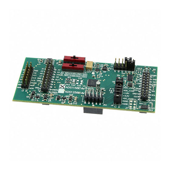
Figure 1. ADS1258EVM (Left) and ADS1258EVM-PDK (Right)
This user's guide describes the characteristics, operation, and use of the ADS1158EVM and
ADS1258EVM, both separately and as part of the ADS1158EVM-PDK or ADS1258EVM-PDK. These
evaluation modules (EVMs) are evaluation board for the
analog-to-digital converter (ADC), and the ADS1158, a 16-bit version of the ADS1258. It allows
evaluation of all aspects of the ADS1158 or ADS1258 device. Complete circuit descriptions, schematic
diagrams, and bills of materials are included in this document.
The related documents listed in
www.ti.com.
Device
ADS1158
ADS1258
REF1004
DAC8571
OPA301
SN74LVC1G126
space
blank
blank
blank
space
blank
blank
blank
blank
ADCPro is a trademark of Texas Instruments.
Microsoft, Windows are registered trademarks of Microsoft Corporation.
All other trademarks are the property of their respective owners.
SBAU126D – May 2007 – Revised May 2016
Submit Documentation Feedback
Table 1
are available through the Texas Instruments web site at
Table 1. EVM-Compatible Device Data Sheets
Literature Number
SBAS429B
SBAS297D
SBVS002
SLAS373A
SBOS271D
SCES224N
ADS1158EVM, ADS1258EVM, ADS1158EVM-PDK, and ADS1258EVM-PDK
Copyright © 2007–2016, Texas Instruments Incorporated
SBAU126D – May 2007 – Revised May 2016
ADS1258EVM-PDK
ADS1258
multi-channel, delta-sigma (ΔΣ),
Device
Literature Number
TPS79225
SLVS337B
SN74AHCT1G04
SCLS319N
SN74LVC1G07
SCES296V
TPS72325
SLVS346B
SN74AVC2T45
SCES531J
SN74AVC8T245
SCES517H
User's Guide
1
Advertisement
Table of Contents

Related Manuals for Texas Instruments ADS1158EVM


Summary of Contents for Texas Instruments ADS1158EVM
- Page 1 ADS1258EVM-PDK Figure 1. ADS1258EVM (Left) and ADS1258EVM-PDK (Right) This user's guide describes the characteristics, operation, and use of the ADS1158EVM and ADS1258EVM, both separately and as part of the ADS1158EVM-PDK or ADS1258EVM-PDK. These evaluation modules (EVMs) are evaluation board for the ADS1258 multi-channel, delta-sigma (ΔΣ),...
-
Page 2: Table Of Contents
EVM-Compatible Device Data Sheets ....................J1—Analog Interface Pinout ................J2—Supplemental Analog Interface Pinout ....................J6—Serial Interface Pins ................... J5 Configuration—Power-Supply Input ADS1158EVM, ADS1258EVM, ADS1158EVM-PDK, and ADS1258EVM-PDK SBAU126D – May 2007 – Revised May 2016 Submit Documentation Feedback Copyright © 2007–2016, Texas Instruments Incorporated... - Page 3 The MMB0 motherboard allows the ADS1158EVM/ADS1258EVM to be connected to the computer via an available USB port. This manual shows how to use the MMB0 as part of the ADS1158EVM- PDK/ADS1258EVM-PDK, but does not provide technical detail on the MMB0 itself.
-
Page 4: Evm Overview
External reference source input (+ side of differential input) J1.12–J1.16 (even) Unused J1.15 Unused J1.9–J19 (odd) AGND Analog ground connections (except J1.15) ADS1158EVM, ADS1258EVM, ADS1158EVM-PDK, and ADS1258EVM-PDK SBAU126D – May 2007 – Revised May 2016 Submit Documentation Feedback Copyright © 2007–2016, Texas Instruments Incorporated... -
Page 5: Digital Interface
C rules. The ADS1258 may run at different logic levels, as set using J4. All ADS1258 pins are therefore level-shifted. SBAU126D – May 2007 – Revised May 2016 ADS1158EVM, ADS1258EVM, ADS1158EVM-PDK, and ADS1258EVM-PDK Submit Documentation Feedback Copyright © 2007–2016, Texas Instruments Incorporated... -
Page 6: J3 Pin Configuration
START and CS. Both FSX and CNTL are pulled down, so these pins can be used to keep START and CS low if they are not to be used. Figure 2. J3 Pin Configuration ADS1158EVM, ADS1258EVM, ADS1158EVM-PDK, and ADS1258EVM-PDK SBAU126D – May 2007 – Revised May 2016 Submit Documentation Feedback... -
Page 7: Power Supplies
Must be connected for operation. 11-12 DGND Connects DGND to board ground. 13-14 AGND Connects AGND to board ground. SBAU126D – May 2007 – Revised May 2016 ADS1158EVM, ADS1258EVM, ADS1158EVM-PDK, and ADS1258EVM-PDK Submit Documentation Feedback Copyright © 2007–2016, Texas Instruments Incorporated... -
Page 8: Voltage Reference
For external operation, a clock signal must be supplied on TOUT on J6 (pin 17), and GPIO2 must be driven high. The level-shifted clock can be measured at TP1. ADS1158EVM, ADS1258EVM, ADS1158EVM-PDK, and ADS1258EVM-PDK SBAU126D – May 2007 – Revised May 2016 Submit Documentation Feedback Copyright ©... -
Page 9: Evm Operation
5-6KInterface HPA-MCUInterface boards available from Texas Instruments, or the MMB0 if purchased as part of the ADS!258EVM-PDK. For a list of compatible interface and/or accessory boards for the EVM, the ADS1258, or the ADS1158, see the relevant product folder on the TI web site (www.ti.com). -
Page 10: Ads1258Evm Default Jumper Locations
EVM and the factory default conditions for each one. Table 8. List of Switches SWITCH DEFAULT POSITION SWITCH DESCRIPTION Left REF positive Left REF negative ADS1158EVM, ADS1258EVM, ADS1158EVM-PDK, and ADS1258EVM-PDK SBAU126D – May 2007 – Revised May 2016 Submit Documentation Feedback Copyright © 2007–2016, Texas Instruments Incorporated... -
Page 11: Ads1258Evm-Pdk Kit Operation
This step will complete when the ADCPro software is executed; see Section 8.5, Running the Software and Completing Driver Installation. SBAU126D – May 2007 – Revised May 2016 ADS1158EVM, ADS1258EVM, ADS1158EVM-PDK, and ADS1258EVM-PDK Submit Documentation Feedback Copyright © 2007–2016, Texas Instruments Incorporated... -
Page 12: Mmb0 Initial Setup
BOOT MODE SWITCH CONNECT IF NEEDED. SEE TEXT . POWER SUPPL Y CONFIG Figure 4. MMB0 Initial Setup ADS1158EVM, ADS1258EVM, ADS1158EVM-PDK, and ADS1258EVM-PDK SBAU126D – May 2007 – Revised May 2016 Submit Documentation Feedback Copyright © 2007–2016, Texas Instruments Incorporated... -
Page 13: Connecting The Ads1258Evm To The Mmb0
About the MMB0 The MMB0 is a Modular EVM System motherboard. It is designed around the TMS320VC5507, a DSP from Texas Instruments that has an onboard USB interface. The MMB0 also has 16MB of SDRAM installed. The MMB0 is not sold as a DSP development board, and it is not available separately. TI cannot offer support for the MMB0 except as part of an EVM kit. -
Page 14: Connecting An Ac Adapter
Output connector: barrel plug (positive center), 2.0-mm I.D. × 5.5-mm O.D. (9-mm insertion depth) NOTE: Use an external power supply that complies with applicable regional safety standards; for example, UL, CSA, VDE, CCC, PSE, and so forth. ADS1158EVM, ADS1258EVM, ADS1158EVM-PDK, and ADS1258EVM-PDK SBAU126D – May 2007 – Revised May 2016 Submit Documentation Feedback... -
Page 15: Laboratory Power-Supply Connection
WALL SUPPL Y CONNECTION POWER SUPPL Y CONFIG POWER +5VDC INPUT (OPTIONAL) 5VDC Figure 7. Laboratory Power-Supply Connection SBAU126D – May 2007 – Revised May 2016 ADS1158EVM, ADS1258EVM, ADS1158EVM-PDK, and ADS1258EVM-PDK Submit Documentation Feedback Copyright © 2007–2016, Texas Instruments Incorporated... - Page 16 8, it is not necessary to search for the software; it has already been installed to your PC. • For the remaining steps, accept the default settings. ADS1158EVM, ADS1258EVM, ADS1158EVM-PDK, and ADS1258EVM-PDK SBAU126D – May 2007 – Revised May 2016 Submit Documentation Feedback Copyright © 2007–2016, Texas Instruments Incorporated...
-
Page 17: Ni-Visa Driver Installation
ADS1258EVM-PDK Kit Operation www.ti.com Figure 8. NI-VISA Driver Installation SBAU126D – May 2007 – Revised May 2016 ADS1158EVM, ADS1258EVM, ADS1158EVM-PDK, and ADS1258EVM-PDK Submit Documentation Feedback Copyright © 2007–2016, Texas Instruments Incorporated... -
Page 18: Ni-Visa Driver Installation Question
ADS1258EVM-PDK Kit Operation www.ti.com Figure 9. NI-VISA Driver Installation Question ADS1158EVM, ADS1258EVM, ADS1158EVM-PDK, and ADS1258EVM-PDK SBAU126D – May 2007 – Revised May 2016 Submit Documentation Feedback Copyright © 2007–2016, Texas Instruments Incorporated... -
Page 19: Ni-Visa Driver Installing
ADS1258EVM-PDK Kit Operation www.ti.com Figure 10. NI-VISA Driver Installing SBAU126D – May 2007 – Revised May 2016 ADS1158EVM, ADS1258EVM, ADS1158EVM-PDK, and ADS1258EVM-PDK Submit Documentation Feedback Copyright © 2007–2016, Texas Instruments Incorporated... -
Page 20: Ni-Visa Driver Complete Installation
Device Manager and locating the driver as shown in Figure Figure 12. NI-VISA Driver Verification Using Device Manager ADS1158EVM, ADS1258EVM, ADS1158EVM-PDK, and ADS1258EVM-PDK SBAU126D – May 2007 – Revised May 2016 Submit Documentation Feedback Copyright © 2007–2016, Texas Instruments Incorporated... -
Page 21: Adcpro Software Start-Up Display Window
1. Start the software by selecting ADCPro from the Windows Start menu. The screen in Figure 13 appears. Figure 13. ADCPro Software Start-up Display Window SBAU126D – May 2007 – Revised May 2016 ADS1158EVM, ADS1258EVM, ADS1158EVM-PDK, and ADS1258EVM-PDK Submit Documentation Feedback Copyright © 2007–2016, Texas Instruments Incorporated... -
Page 22: Ads1258Evm-Pdk Plug-In Display Window
NOTE: During the driver installation, a message may appear indicating the firmware load has TIMED OUT. Click OK and continue driver installation. The plug-in will attempt to download the firmware again once the driver installation completes. ADS1158EVM, ADS1258EVM, ADS1158EVM-PDK, and ADS1258EVM-PDK SBAU126D – May 2007 – Revised May 2016 Submit Documentation Feedback... -
Page 23: Install New Driver Wizard Screen
ADS1258EVM-PDK Kit Operation www.ti.com Figure 15. Install New Driver Wizard Screen 1 Figure 16. Install New Driver Wizard Screen 2 SBAU126D – May 2007 – Revised May 2016 ADS1158EVM, ADS1258EVM, ADS1158EVM-PDK, and ADS1258EVM-PDK Submit Documentation Feedback Copyright © 2007–2016, Texas Instruments Incorporated... - Page 24 ADS1258EVM-PDK Kit Operation www.ti.com Figure 17. Install New Driver Wizard Screen 3 Figure 18. Install New Driver Wizard Screen 4 ADS1158EVM, ADS1258EVM, ADS1158EVM-PDK, and ADS1258EVM-PDK SBAU126D – May 2007 – Revised May 2016 Submit Documentation Feedback Copyright © 2007–2016, Texas Instruments Incorporated...
-
Page 25: Usbsytx Driver Verification Using Device Manager
The driver installation wizard sequence should not appear again, unless you connect the board to a different USB port. SBAU126D – May 2007 – Revised May 2016 ADS1158EVM, ADS1258EVM, ADS1158EVM-PDK, and ADS1258EVM-PDK Submit Documentation Feedback Copyright © 2007–2016, Texas Instruments Incorporated... -
Page 26: Evaluating With The Adcpro Software
1, 4, 16, or 64. Note that this is a setting for the ADS1258 device itself; no software averaging is done in the ADS1258EVM-PDK plug-in. ADS1158EVM, ADS1258EVM, ADS1158EVM-PDK, and ADS1258EVM-PDK SBAU126D – May 2007 – Revised May 2016 Submit Documentation Feedback Copyright ©... -
Page 27: Mux Settings For Fixed Channel Mode
AINP were set to AIN1, and AINN were set to AIN0, then the signal could be applied between AIN1 and AIN0. SBAU126D – May 2007 – Revised May 2016 ADS1158EVM, ADS1258EVM, ADS1158EVM-PDK, and ADS1258EVM-PDK Submit Documentation Feedback Copyright © 2007–2016, Texas Instruments Incorporated... -
Page 28: Mux Settings For Auto Channel Mode
Also notice when changing from Fixed Channel mode to Auto Scan mode, the data rate will be changed to match the limits of the ADS1258. Figure 22. Mux Settings for Auto Channel Mode ADS1158EVM, ADS1258EVM, ADS1158EVM-PDK, and ADS1258EVM-PDK SBAU126D – May 2007 – Revised May 2016 Submit Documentation Feedback... -
Page 29: Switch Delay Settings
The ADS1258 averages the two readings, canceling the offset as shown in Figure Multiplexer (chopping) MUXOUTP ADCINP AINn Optional Signal Conditioning AINn MUXOUTN ADCINN Figure 24. External Chopping SBAU126D – May 2007 – Revised May 2016 ADS1158EVM, ADS1258EVM, ADS1158EVM-PDK, and ADS1258EVM-PDK Submit Documentation Feedback Copyright © 2007–2016, Texas Instruments Incorporated... -
Page 30: Chopping Settings
Evaluating with the ADCPro Software www.ti.com This action can be enabled on the Chopping tab shown in Figure Figure 25. Chopping Settings ADS1158EVM, ADS1258EVM, ADS1158EVM-PDK, and ADS1258EVM-PDK SBAU126D – May 2007 – Revised May 2016 Submit Documentation Feedback Copyright © 2007–2016, Texas Instruments Incorporated... -
Page 31: Clock Settings
When MMB0 is selected, a 4MHz to 20MHz clock is supplied to the ADS1258EVM. The default frequency is 16MHz, but it can be adjusted in the Clock Frequency control. SBAU126D – May 2007 – Revised May 2016 ADS1158EVM, ADS1258EVM, ADS1158EVM-PDK, and ADS1258EVM-PDK Submit Documentation Feedback Copyright © 2007–2016, Texas Instruments Incorporated... -
Page 32: Gpio Controls
(lit for HIGH and unlit for LOW). The state of the GPIO pins is sampled only when the Input button is pressed—in other words, the display will only update when this pin is pressed. ADS1158EVM, ADS1258EVM, ADS1158EVM-PDK, and ADS1258EVM-PDK SBAU126D – May 2007 – Revised May 2016 Submit Documentation Feedback Copyright ©... -
Page 33: Power And Reference Settings
The Low Supply indicator will indicate that the analog supply voltage (AVDD – AVSS) is less than about 4.3V. SBAU126D – May 2007 – Revised May 2016 ADS1158EVM, ADS1258EVM, ADS1158EVM-PDK, and ADS1258EVM-PDK Submit Documentation Feedback Copyright © 2007–2016, Texas Instruments Incorporated... -
Page 34: Progress Bar While Collecting Data
If ADCPro stops responding while the ADS1258EVM-PDK is connected, try unplugging the power supply from the PDK. Unload and reload the plug-in before reapplying power to the PDK. ADS1158EVM, ADS1258EVM, ADS1158EVM-PDK, and ADS1258EVM-PDK SBAU126D – May 2007 – Revised May 2016 Submit Documentation Feedback Copyright ©... -
Page 35: Schematics And Layout
Samtec TSM-105-01-L-DV-P 10-pin SMT Socket Samtec SSW-105-22-F-D-VS-K Header Strip, 16 pin Samtec TSW-108-07-L-D Header Strip, 14-pin Samtec TSW-107-07-L-D SBAU126D – May 2007 – Revised May 2016 ADS1158EVM, ADS1258EVM, ADS1158EVM-PDK, and ADS1258EVM-PDK Submit Documentation Feedback Copyright © 2007–2016, Texas Instruments Incorporated... - Page 36 ..........• Updated software download links in the Installing the ADCPro Software section.............. • Added External Wall-Adapter Power-Supply Requirements section. Revision History SBAU126D – May 2007 – Revised May 2016 Submit Documentation Feedback Copyright © 2007–2016, Texas Instruments Incorporated...
- Page 37 REVISION HISTORY ENGINEERING CHANGE NUMBER APPROVED DVDD +3.3V 0.1U 0.1U HEADER-6X2 ADS1258IRTC +3.3V AVDD DVDD VCCA VCCB AIN0 AIN1 GPIO0 GPIO1 100K 100K AIN2 GPIO1 DVDD +3.3V AIN3 GPIO2 SN74AVC2T45DCT GPIO3 AIN4 GPIO3 AIN5 GPIO4 0.1U GPIO5 AIN6 GPIO5 0.1U AIN7 GPIO6 VCCA...
- Page 38 STANDARD TERMS AND CONDITIONS FOR EVALUATION MODULES Delivery: TI delivers TI evaluation boards, kits, or modules, including any accompanying demonstration software, components, or documentation (collectively, an “EVM” or “EVMs”) to the User (“User”) in accordance with the terms and conditions set forth herein. Acceptance of the EVM is expressly subject to the following terms and conditions.
- Page 39 FCC Interference Statement for Class B EVM devices NOTE: This equipment has been tested and found to comply with the limits for a Class B digital device, pursuant to part 15 of the FCC Rules. These limits are designed to provide reasonable protection against harmful interference in a residential installation.
- Page 40 【無線電波を送信する製品の開発キットをお使いになる際の注意事項】 開発キットの中には技術基準適合証明を受けて いないものがあります。 技術適合証明を受けていないもののご使用に際しては、電波法遵守のため、以下のいずれかの 措置を取っていただく必要がありますのでご注意ください。 1. 電波法施行規則第6条第1項第1号に基づく平成18年3月28日総務省告示第173号で定められた電波暗室等の試験設備でご使用 いただく。 2. 実験局の免許を取得後ご使用いただく。 3. 技術基準適合証明を取得後ご使用いただく。 なお、本製品は、上記の「ご使用にあたっての注意」を譲渡先、移転先に通知しない限り、譲渡、移転できないものとします。 上記を遵守頂けない場合は、電波法の罰則が適用される可能性があることをご留意ください。 日本テキサス・イ ンスツルメンツ株式会社 東京都新宿区西新宿6丁目24番1号 西新宿三井ビル 3.3.3 Notice for EVMs for Power Line Communication: Please see http://www.tij.co.jp/lsds/ti_ja/general/eStore/notice_02.page 電力線搬送波通信についての開発キットをお使いになる際の注意事項については、次のところをご覧くださ い。http://www.tij.co.jp/lsds/ti_ja/general/eStore/notice_02.page SPACER EVM Use Restrictions and Warnings: 4.1 EVMS ARE NOT FOR USE IN FUNCTIONAL SAFETY AND/OR SAFETY CRITICAL EVALUATIONS, INCLUDING BUT NOT LIMITED TO EVALUATIONS OF LIFE SUPPORT APPLICATIONS.
- Page 41 Notwithstanding the foregoing, any judgment may be enforced in any United States or foreign court, and TI may seek injunctive relief in any United States or foreign court. Mailing Address: Texas Instruments, Post Office Box 655303, Dallas, Texas 75265 Copyright © 2015, Texas Instruments Incorporated...
- Page 42 IMPORTANT NOTICE Texas Instruments Incorporated and its subsidiaries (TI) reserve the right to make corrections, enhancements, improvements and other changes to its semiconductor products and services per JESD46, latest issue, and to discontinue any product or service per JESD48, latest issue.
- Page 43 Mouser Electronics Authorized Distributor Click to View Pricing, Inventory, Delivery & Lifecycle Information: Texas Instruments ADS1158EVM-PDK ADS1158EVM ADS1258EVM ADS1258EVM-PDK...
Need help?
Do you have a question about the ADS1158EVM and is the answer not in the manual?
Questions and answers