Table of Contents
Advertisement
Quick Links
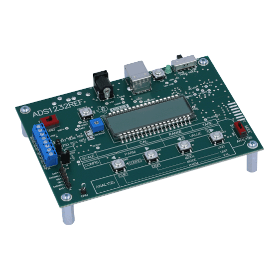
The ADS1232REF is a reference design for the
(ADC). It contains all the circuitry and user interface elements needed for a weigh-scale digitizer, and is
meant as an example of good design for a basic weigh-scale system. The ADS1232REF is also suitable
for general evaluation of the ADS1232 device. Additionally, performance results obtained with the
ADS1232REF are applicable to the ADS1234, a device with identical performance.
The ADS1232REF hardware has the following features:
•
ADS1232 ADC
•
Connections for load cells or other voltage sources
•
Low-side excitation switch on the load cell header connector
•
Ample EMI/RFI suppression between the ADC and rest of design
•
Eight-digit starburst LCD readout
•
USB connection for firmware updates and remote control
•
Designed for very low power consumption
•
Battery (9V) or wall power
Version 1.1.0 of the firmware includes the following features:
•
Weigh-scale mode with two-point calibration
•
Complete configuration of the device
•
Real-time peak-to-peak and RMS noise calculation
•
Autoranging voltage display
•
Noise displayed in volts, codes, and bits
•
Voltage displayed in volts or codes
•
Adjustable averaging mode
•
Raw hexadecimal code display
•
Simple and fast configuration
•
Parameters saved to internal flash memory
•
Computer link
Graphical PC software is also provided for histogram display, datalogging, and device control.
We welcome bug reports and suggestions for additional features; please contact the Texas Instruments
Precision Analog Applications Group.
Hyperterm is a trademark of Microsoft Corporation.
Windows is a registered trademark of Microsoft Corporation.
All other trademarks are the property of their respective owners.
SBAU120B – November 2005 – Revised July 2011
Submit Documentation Feedback
ADS1232REF User's Guide
ADS1232
Copyright © 2005–2011, Texas Instruments Incorporated
SBAU120B – November 2005 – Revised July 2011
24-bit, delta-sigma analog-to-digital converter
ADS1232REF User's Guide
User's Guide
1
Advertisement
Table of Contents

Related Manuals for Texas Instruments ADS1232REF


Summary of Contents for Texas Instruments ADS1232REF
- Page 1 (ADC). It contains all the circuitry and user interface elements needed for a weigh-scale digitizer, and is meant as an example of good design for a basic weigh-scale system. The ADS1232REF is also suitable for general evaluation of the ADS1232 device. Additionally, performance results obtained with the ADS1232REF are applicable to the ADS1234, a device with identical performance.
-
Page 2: Table Of Contents
Parameters in Analysis Mode ....................Console Mode Commands ....................Load Cell Header Pinout ..................... Terminal Block Pinout ..................ADS1232REF Bill of Materials SBAU120B – November 2005 – Revised July 2011 ADS1232REF User's Guide Submit Documentation Feedback Copyright © 2005–2011, Texas Instruments Incorporated... -
Page 3: Getting Started
The ADS1232REF operates in one of three modes: • Scale mode: When the mode select switch is in Scale position, the ADS1232REF acts as a basic weigh scale. The scale has tare, range, and calibrate functions, and can display metric (SI) units. Other parameters can be configured in configuration screens. -
Page 4: 4-Wire Load Cell To Terminal Block
Powering the Board To apply power to the ADS1232REF, connect a 9V battery or plug in a 6V to 9V ac wall adapter. AC adapters must be tip positive/sleeve negative. When an ac adapter is plugged in, the board always takes power from it, and not from the battery. -
Page 5: 6-Wire Load Cell To Terminal Block
For this configuration, the reference select switch should be in the EXT position for best performance. The +5V position also works, but the device may not perform as well. SBAU120B – November 2005 – Revised July 2011 ADS1232REF User's Guide Submit Documentation Feedback Copyright © 2005–2011, Texas Instruments Incorporated... - Page 6 Getting Started www.ti.com Connecting Other Sources In general, the ADS1232REF can accurately measure any voltage in the input range of the ADS1232 ADC, as long as the following rules are observed: • Never apply a negative voltage to the inputs of the ADS1232REF. The ADS1232 cannot accept negative voltages at its input.
-
Page 7: Weigh Scale Mode
Obtaining a calibration weight: Before the ADS1232REF can display the mass of an object, it must measure the output of the load cell for a previously known mass. The known mass can be adjusted. At power-up, the ADS1232REF expects a 5kg mass. If this mass is not available, or if the load cell range is not compatible with this mass, the calibration mass can be changed in the following manner: 1. -
Page 8: Unit Conversion Factors And Display Formats
The display format for stone differs from the format used for the other units. One stone is equal to fourteen pounds; weight in stone is commonly expressed as a number of stone followed by a number of pounds. On the ADS1232REF, two digits are shown for stone, followed by st, followed by pounds displayed to two decimal places. -
Page 9: Parameters In Configuration Mode
Offset calibration; see text — Save parameters SAVE? Save parameters; see text Version number V1.1.0 — Firmware version number display SBAU120B – November 2005 – Revised July 2011 ADS1232REF User's Guide Submit Documentation Feedback Copyright © 2005–2011, Texas Instruments Incorporated... - Page 10 Version number: This screen displays the version number of the ADS1232REF firmware. The ADS1232REF cannot detect the frequency of the ADS1232 master clock, so it cannot display the actual data rate of the ADS1232 device.
-
Page 11: Analysis Mode
Analysis Mode www.ti.com Analysis Mode In Analysis mode, the ADS1232REF analyzes code output from the ADS1232 and displays it in different ways. Table 3 summarizes the numerous display modes available, together with example displays. Table 3. Modes and Example Displays... -
Page 12: Voltage Display Ranges
When the bar graph reaches all the way to the right, the new result is generated and collection restarts. SBAU120B – November 2005 – Revised July 2011 ADS1232REF User's Guide Submit Documentation Feedback Copyright © 2005–2011, Texas Instruments Incorporated... -
Page 13: Parameters In Analysis Mode
ADS1232 to enter power-down mode. This action occurs by pulling the PDWN line low. While the PDWN line is low, the display reads POWER DN. When a button is pressed from this display, the ADS1232REF powers the converter on and returns to the analysis display, exiting configuration mode. -
Page 14: Using The Pc Software
USB connection. It also provides a means of recording received data to a file. The software is designed to be used with the ADS1232REF operating in Analysis mode. Not all commands will work with the ADS1232REF operating in Scale mode; the results will be unpredictable. -
Page 15: Ads1232Ref Software Display
To do this step, it opens every available serial port in turn, testing it to see if there is an ADS1232REF connected. The program uses the first ADS1232REF it finds. -
Page 16: Ads1232Ref Average Data
The strip chart display shows both the full precision result of the averages and the integer version, as illustrated in Figure Strip Chart Histogram Figure 7. ADS1232REF Average Data SBAU120B – November 2005 – Revised July 2011 ADS1232REF User's Guide Submit Documentation Feedback Copyright © 2005–2011, Texas Instruments Incorporated... - Page 17 This processing delay is timed so that the display updates at least every 0.75 seconds. Data Recording The ADS1232REF software can record incoming samples to a text file. This file can be loaded into other programs for analysis. Data recording is performed using the controls in the Recording box.
-
Page 18: Serial Console
4.7.1 File Format Data files begin with a header that contains the text collected from ADS1232REF, the time of recording, and the speed and gain. Following this header, values are written in either volts or raw codes, with one value per line. Line separators are in DOS format, consisting of a carriage return and a line feed. This format can be examined in a text editor and loaded or imported into most other software, including spreadsheets. -
Page 19: Console Mode Commands
Displays a message containing the firmware version and copyright notice. 5.2.5 S—Start Streaming When S is issued, the ADS1232REF begins printing raw output codes from the ADS1232 in hexadecimal format, separated by new lines. The device iterates continuously until a character is received from the serial port. -
Page 20: Hardware
CT—sets input channel to specified temperature • C—(with no arguments) provides the current channel setting 5.2.8 Q—Query Parameters Q causes the ADS1232REF to issue a coded string summarizing the current settings. The format of the string is: P[0-3]R[F,S]OIC[0,1,T] followed by a carriage-return and linefeed. Hardware... -
Page 21: Load Cell Header Pinout
User Interface The ADS1232REF user interface consists of the display and switches SW2–5 and SW8. Switches are connected to interrupt-capable GPIOs on the microcontroller, allowing them to wake the microcontroller from sleep mode. -
Page 22: Terminal Block Pinout
USB interface module, a microcontroller, and a 16550-type UART. Driver software is available that causes the device to appear as a serial port on the host PC. The USB interface is powered separately from the rest of the ADS1232REF; it takes power from the USB line, through linear regulator U3. -
Page 23: Appendix A Schematic And Layout
USB. This feature also protects the microcontroller from unknown states on these pins at power-up. Appendix A Schematic and Layout The printed circuit board (PCB) layouts for the top and bottom sides of the ADS1232REF are shown in Figure 9 Figure 10, respectively. - Page 24 Bill of Materials www.ti.com Table 9. ADS1232REF Bill of Materials (continued) REFERENCE DESIGNATOR DESCRIPTION MANUFACTURER MFG. PART NUMBER Linear Voltage Regulator, +5V Texas Instruments TPS76350DBVG4 USB to Serial Converter Texas Instruments TUSB3410VFG4 Analog Switch, SPST Texas Instruments TS5A3166DCKR U8, U9...
-
Page 25: Ads1232Ref Pcb-Top Side
PCB Layout www.ti.com PCB Layout Figure 9. ADS1232REF PCB—Top Side Figure 10. ADS1232REF PCB—Bottom Side SBAU120B – November 2005 – Revised July 2011 Schematic and Layout Submit Documentation Feedback Copyright © 2005–2011, Texas Instruments Incorporated... -
Page 26: Ads1232Ref Schematic-Adc
Schematics www.ti.com Schematics Figure 11. ADS1232REF Schematic—ADC SBAU120B – November 2005 – Revised July 2011 Schematic and Layout Submit Documentation Feedback Copyright © 2005–2011, Texas Instruments Incorporated... -
Page 27: Ads1232Ref Schematic-Mcu
Schematics www.ti.com R13 100 R12 100 Figure 12. ADS1232REF Schematic—MCU SBAU120B – November 2005 – Revised July 2011 Schematic and Layout Submit Documentation Feedback Copyright © 2005–2011, Texas Instruments Incorporated... -
Page 28: Ads1232Ref Schematic-Usb
Schematics www.ti.com Figure 13. ADS1232REF Schematic—USB SBAU120B – November 2005 – Revised July 2011 Schematic and Layout Submit Documentation Feedback Copyright © 2005–2011, Texas Instruments Incorporated... - Page 29 Changed first paragraph of Section 4 NOTE: Page numbers for previous revisions may differ from page numbers in the current version. SBAU120B – November 2005 – Revised July 2011 Revision History Submit Documentation Feedback Copyright © 2005–2011, Texas Instruments Incorporated...
- Page 30 IMPORTANT NOTICE Texas Instruments Incorporated and its subsidiaries (TI) reserve the right to make corrections, modifications, enhancements, improvements, and other changes to its products and services at any time and to discontinue any product or service without notice. Customers should obtain the latest relevant information before placing orders and should verify that such information is current and complete.
Need help?
Do you have a question about the ADS1232REF and is the answer not in the manual?
Questions and answers