Table of Contents
Advertisement
Quick Links
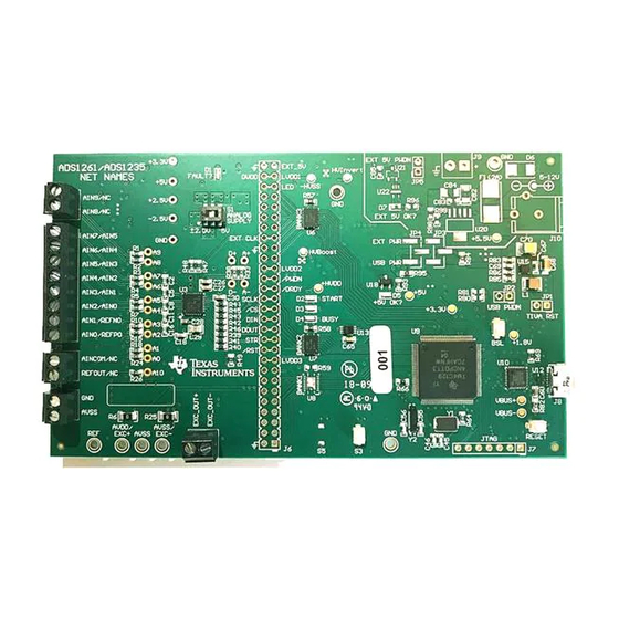
ADS1261, ADS1235 Evaluation Module (ADS1261EVM Shown)
The ADS1261EVM and ADS1235EVM are evaluation module kits providing hardware and software
support for evaluation of the ADS1261, or ADS1235, delta-sigma analog-to-digital converter (ADC). The
kit utilizes the TM4C1294NCPDT processor to communicate with the ADC via SPI and provide
communication with a PC over USB interface. The kit also includes a software application that runs on a
PC allowing for register manipulation and data collection from the ADC. The ADS1261 and ADS1235 EVM
kit include the ADS12xx device along with a USB micro cable and downloadable supporting software
(SW).
This document includes a detailed description of the hardware (HW), software, bill of materials, and
schematic for the EVM.
Throughout this document, the term EVM is synonymous with ADS1261EVM and ADS1235EVM,
demonstration kit, and evaluation module. The term EVM applies to both the ADS1261EVM and
ADS1235EVM. The term GUI is synonymous with Delta-Sigma ADC EvaluaTIon Software, core
application, and EVM software. The use of Tiva™ is synonymous with the TM4C1294NCPDT
microcontroller.
SBAU293 – March 2018
Submit Documentation Feedback
ADVANCE INFORMATION
ADS1261 and ADS1235 Evaluation Module
Table 1. Related Documentation
Device
ADS1261
ADS1235
Copyright © 2018, Texas Instruments Incorporated
Literature Number
SBAS760
SBAS824
ADS1261 and ADS1235 Evaluation Module
User's Guide
SBAU293 – March 2018
1
Advertisement
Table of Contents

Subscribe to Our Youtube Channel
Related Manuals for Texas Instruments ADS1261EVM


Summary of Contents for Texas Instruments ADS1261EVM
- Page 1 EVM. Throughout this document, the term EVM is synonymous with ADS1261EVM and ADS1235EVM, demonstration kit, and evaluation module. The term EVM applies to both the ADS1261EVM and ADS1235EVM. The term GUI is synonymous with Delta-Sigma ADC EvaluaTIon Software, core application, and EVM software.
-
Page 2: Table Of Contents
ADS1261EVM USB Power Schematic ................ADS1261EVM External Power Schematic Trademarks Tiva is a trademark of Texas Instruments, Incorporated. Microsoft, Windows are registered trademarks of Microsoft Corporation. All other trademarks are the property of their respective owners. ADS1261 and ADS1235 Evaluation Module SBAU293 –... -
Page 3: Evm Overview
• Error detection through device status information • CRC of data and SPI communication (for error prevention or detection of data transmission) SBAU293 – March 2018 ADS1261 and ADS1235 Evaluation Module Submit Documentation Feedback Copyright © 2018, Texas Instruments Incorporated... -
Page 4: Quick Start
The analog supply polarity can be selected by S1. When switching S1, TI recommends disconnecting the USB cable from the EVM, toggling the switch, and then reconnecting the USB cable. ADS1261 and ADS1235 Evaluation Module SBAU293 – March 2018 Submit Documentation Feedback Copyright © 2018, Texas Instruments Incorporated... -
Page 5: Software Installation And Hardware Connection Procedure
Use the following steps at startup: 1. Install the GUI software on the PC. 2. Install the device package software on the PC. (ADS1261 Device Package for the ADS1261EVM and ADS1235 Device Package for the ADS1235EVM.) 3. Ensure all jumpers and switches are configured in the default configuration per... -
Page 6: Hardware Reference
Total Tiva FLASH erasure (on reset Tiva enumerates as a DFU device) RESET) Open (normally) Normal operation Switch is DPDT. Pin 1 is identified with a dot on the PCB silkscreen. ADS1261 and ADS1235 Evaluation Module SBAU293 – March 2018 Submit Documentation Feedback Copyright © 2018, Texas Instruments Incorporated... -
Page 7: Header, Connector, And Test Point Reference
Pin 4 Pin 5 Pin 6 Pin 7 Pin 8 Pin 1 Pin 2 Pin 1 Pin 2 Figure 2. Input Terminal Blocks SBAU293 – March 2018 ADS1261 and ADS1235 Evaluation Module Submit Documentation Feedback Copyright © 2018, Texas Instruments Incorporated... - Page 8 ADC. Before applying an external clock, be sure to disable the GPIO output on this pin by sending the "HOLDCLOCK 0" command, described in Table ADS1261 and ADS1235 Evaluation Module SBAU293 – March 2018 Submit Documentation Feedback Copyright © 2018, Texas Instruments Incorporated...
- Page 9 Restrictions ADC side Analog input (ADS1261EVM: AIN9) Probe only Analog input (ADS1261EVM: AIN8) Probe only Analog input (ADS1261EVM: AIN7, ADS1235EVM: AIN5) Probe only Analog input (ADS1261EVM: AIN6, ADS1235EVM: AIN4) Probe only Analog input (ADS1261EVM: AIN5, ADS1235EVM: AIN3) Probe only Analog input (ADS1261EVM: AIN4, ADS1235EVM: AIN2)
- Page 10 Inverting dc/dc converter output (U25 - not populated) HVInvert Probe only Negative high-voltage linear regulator (U26 - not populated) –HVSS Probe only ADS1261 and ADS1235 Evaluation Module SBAU293 – March 2018 Submit Documentation Feedback Copyright © 2018, Texas Instruments Incorporated...
-
Page 11: Software Details
Run the installer and follow the on-screen prompts. Note that future software versions may show slightly different screens. Figure 3. Delta-Sigma Evaluation Engine Installation Instructions SBAU293 – March 2018 ADS1261 and ADS1235 Evaluation Module Submit Documentation Feedback Copyright © 2018, Texas Instruments Incorporated... -
Page 12: Device Package Installation Instructions
Note that future software versions may show slightly different screens. STEP 1 STEP 2 STEP 3 STEP 4 Figure 4. Device Package Installation Instructions ADS1261 and ADS1235 Evaluation Module SBAU293 – March 2018 Submit Documentation Feedback Copyright © 2018, Texas Instruments Incorporated... -
Page 13: Connecting To The Evm Hardware
EVM commands that are utilized by the GUI. Refer to the "Wakes Device?" column in Table 7 determine the intended behavior of the EVM firmware. SBAU293 – March 2018 ADS1261 and ADS1235 Evaluation Module Submit Documentation Feedback Copyright © 2018, Texas Instruments Incorporated... - Page 14 Resetting will wake the device from software-power down mode. Setting the /PDWN pin high exits hardware power-down mode; however, the previous software power-down mode will remain unchanged. ADS1261 and ADS1235 Evaluation Module SBAU293 – March 2018 Submit Documentation Feedback Copyright © 2018, Texas Instruments Incorporated...
-
Page 15: Evm Bill Of Materials, Pcb Layouts, And Schematics
EVM Bill of Materials, PCB Layouts, and Schematics The bill of materials and schematics are shown for the ADS1261EVM only. The main difference between the ADS1261EVM and the ADS1235EVM is with respect to which device is populated, as well as additional components which are not installed on the ADS1235EVM. Components that are... - Page 16 RES, 215 k, 1%, 0.1 W, 0603 0603 RC0603FR-07215KL Yageo America SLIDE SWITCH DPDT .1A, SMT SWITCH, 5.4x2.5x3.9mm CAS-220TA Copal Electronics Component is not populated on the ADS1235EVM. ADS1261 and ADS1235 Evaluation Module SBAU293 – March 2018 Submit Documentation Feedback Copyright © 2018, Texas Instruments Incorporated...
- Page 17 CAP, CERM, 10 uF, 35 V, ±10%, X7R, 1206 1206 GMK316AB7106KL Taiyo Yuden C96, C100, C101 For the ADS1235EVM, U3 is replaced with the ADS1235IRHBR. SBAU293 – March 2018 ADS1261 and ADS1235 Evaluation Module Submit Documentation Feedback Copyright © 2018, Texas Instruments Incorporated...
- Page 18 RES, 15.0 k, 1%, 0.1 W, AEC-Q200 Grade 0, 0603 0603 CRCW060315K0FKEA Vishay-Dale R103 51.1k RES, 51.1 k, 1%, 0.1 W, AEC-Q200 Grade 0, 0603 0603 CRCW060351K1FKEA Vishay-Dale ADS1261 and ADS1235 Evaluation Module SBAU293 – March 2018 Submit Documentation Feedback Copyright © 2018, Texas Instruments Incorporated...
- Page 19 V Output, -3 to -36 V Input, with Ultra-Low Noise, 8-pin MSOP (DGN), -40 to 125 degC, Green (RoHS & no Sb/Br) SBAU293 – March 2018 ADS1261 and ADS1235 Evaluation Module Submit Documentation Feedback Copyright © 2018, Texas Instruments Incorporated...
-
Page 20: Pcb Layouts
PCB Layouts Figure 7 through Figure 12 illustrate the PCB layout. The same PCB is used for both the ADS1261EVM and ADS1235EVM. Figure 7. Top Silkscreen Figure 8. Top Layer (Positive) Figure 9. Ground Layer (Negative) ADS1261 and ADS1235 Evaluation Module SBAU293 –... -
Page 21: Power Layer (Negative)
EVM Bill of Materials, PCB Layouts, and Schematics www.ti.com Figure 10. Power Layer (Negative) Figure 11. Bottom Layer (Positive) Figure 12. Bottom Silkscreen SBAU293 – March 2018 ADS1261 and ADS1235 Evaluation Module Submit Documentation Feedback Copyright © 2018, Texas Instruments Incorporated... -
Page 22: Schematic
High-Speed USB ULPI 2.0 tranceiver Fault LED (USB3320C) JTAG Header LEDs Buttons (Not Installed) 3.3V 1.8V Figure 13. ADS1261EVM Block Diagram Schematic ADS1261 and ADS1235 Evaluation Module SBAU293 – March 2018 Submit Documentation Feedback Copyright © 2018, Texas Instruments Incorporated... -
Page 23: Ads1261Evm Analog Inputs Schematic
2.2uF REFN0 FILT GND_F REF6225IDGKR REFN1 REF6225IDGKR may be AVSS AVSS substituted with the AVSS REF6250IDGKR Figure 14. ADS1261EVM Analog Inputs Schematic SBAU293 – March 2018 ADS1261 and ADS1235 Evaluation Module Submit Documentation Feedback Copyright © 2018, Texas Instruments Incorporated... -
Page 24: Ads1261Evm Adc Main Schematic
+3.3V CPOUT +2.5V OUT+ 4.7uF 604k 4.7uF 2.2uF 549k PGOOD 511k 2.2uF 536k -2.5V OUT- LM27762DSSR Figure 15. ADS1261EVM ADC Main Schematic ADS1261 and ADS1235 Evaluation Module SBAU293 – March 2018 Submit Documentation Feedback Copyright © 2018, Texas Instruments Incorporated... -
Page 25: Ads1261Evm Digital Header Schematic
I2C1SDA (Connection to 'TM4C_Main' page) I2C4SDA I2C4SCL BANK_ENABLE LVDD3 +3.3V VCCB VCCA TXS0108ERGY 100k 0.1uF 0.1uF Figure 16. ADS1261EVM Digital Header Schematic SBAU293 – March 2018 ADS1261 and ADS1235 Evaluation Module Submit Documentation Feedback Copyright © 2018, Texas Instruments Incorporated... -
Page 26: Ads1261Evm Usb And Peripherals Schematic
0.1uF 10.0k 10.0k EEPROM WP Pin Connection: - GND: Writing enabled - VCC: Writing disabled Figure 17. ADS1261EVM USB and Peripherals Schematic ADS1261 and ADS1235 Evaluation Module SBAU293 – March 2018 Submit Documentation Feedback Copyright © 2018, Texas Instruments Incorporated... -
Page 27: Ads1261Evm Processor Main Schematic
This jumper is used to hold TIVA in reset and disable level shifters when using TM4C1294NCPDTI3R 2.2uF 0.1uF external microprocessor/microcontroller Figure 18. ADS1261EVM Processor Main Schematic SBAU293 – March 2018 ADS1261 and ADS1235 Evaluation Module Submit Documentation Feedback Copyright © 2018, Texas Instruments Incorporated... -
Page 28: Ads1261Evm Usb Power Schematic
1000pF TPS737xxDRV Jumper Position DVDD (JP3) AVDD (JP10) USB 5V USB 5V EXT 5V EXT 5V Figure 19. ADS1261EVM USB Power Schematic ADS1261 and ADS1235 Evaluation Module SBAU293 – March 2018 Submit Documentation Feedback Copyright © 2018, Texas Instruments Incorporated... -
Page 29: Ads1261Evm External Power Schematic
EP GND R108 R109 121k C103 10.0k PS_GND 0.01uF R110 TPS63700DRCR 10uH C104 10.0 0.22uF C105 0.1uF Figure 20. ADS1261EVM External Power Schematic SBAU293 – March 2018 ADS1261 and ADS1235 Evaluation Module Submit Documentation Feedback Copyright © 2018, Texas Instruments Incorporated... - Page 30 STANDARD TERMS FOR EVALUATION MODULES Delivery: TI delivers TI evaluation boards, kits, or modules, including any accompanying demonstration software, components, and/or documentation which may be provided together or separately (collectively, an “EVM” or “EVMs”) to the User (“User”) in accordance with the terms set forth herein.
- Page 31 FCC Interference Statement for Class B EVM devices NOTE: This equipment has been tested and found to comply with the limits for a Class B digital device, pursuant to part 15 of the FCC Rules. These limits are designed to provide reasonable protection against harmful interference in a residential installation.
- Page 32 【無線電波を送信する製品の開発キットをお使いになる際の注意事項】 開発キットの中には技術基準適合証明を受けて いないものがあります。 技術適合証明を受けていないもののご使用に際しては、電波法遵守のため、以下のいずれかの 措置を取っていただく必要がありますのでご注意ください。 1. 電波法施行規則第6条第1項第1号に基づく平成18年3月28日総務省告示第173号で定められた電波暗室等の試験設備でご使用 いただく。 2. 実験局の免許を取得後ご使用いただく。 3. 技術基準適合証明を取得後ご使用いただく。 なお、本製品は、上記の「ご使用にあたっての注意」を譲渡先、移転先に通知しない限り、譲渡、移転できないものとします。 上記を遵守頂けない場合は、電波法の罰則が適用される可能性があることをご留意ください。 日本テキサス・イ ンスツルメンツ株式会社 東京都新宿区西新宿6丁目24番1号 西新宿三井ビル 3.3.3 Notice for EVMs for Power Line Communication: Please see http://www.tij.co.jp/lsds/ti_ja/general/eStore/notice_02.page 電力線搬送波通信についての開発キットをお使いになる際の注意事項については、次のところをご覧ください。http:/ /www.tij.co.jp/lsds/ti_ja/general/eStore/notice_02.page 3.4 European Union 3.4.1 For EVMs subject to EU Directive 2014/30/EU (Electromagnetic Compatibility Directive): This is a class A product intended for use in environments other than domestic environments that are connected to a low-voltage power-supply network that supplies buildings used for domestic purposes.
- Page 33 Notwithstanding the foregoing, any judgment may be enforced in any United States or foreign court, and TI may seek injunctive relief in any United States or foreign court. Mailing Address: Texas Instruments, Post Office Box 655303, Dallas, Texas 75265 Copyright © 2018, Texas Instruments Incorporated...
- Page 34 IMPORTANT NOTICE FOR TI DESIGN INFORMATION AND RESOURCES Texas Instruments Incorporated (‘TI”) technical, application or other design advice, services or information, including, but not limited to, reference designs and materials relating to evaluation modules, (collectively, “TI Resources”) are intended to assist designers who are developing applications that incorporate TI products;...
Need help?
Do you have a question about the ADS1261EVM and is the answer not in the manual?
Questions and answers