Table of Contents
Advertisement
Quick Links
www.ti.com
User's Guide
ADS1263EVM-PDK Evaluation Module
This user's guide describes the characteristics, operation, and use of the
This EVM is an evaluation platform for the Texas Instruments ADS1263, a low-noise, 32-bit, 38-kSPS,
10-channel (multiplexed), delta-sigma (ΔΣ) analog-to-digital converter (ADC). The highly-integrated ADS1263
includes a programmable gain amplifier (PGA), a 2.5-V low-drift voltage reference, an internal oscillator,
dual-sensor excitation current sources (IDAC), several system-monitoring features, and an auxiliary 24-bit
ΔΣ ADC. The integrated features and excellent performance of the ADS1263 enable precision measurement
of strain gauges, weigh scales, pressure sensors, thermocouples, thermistors, and resistance temperature
detectors (RTDs). The ADS1263EVM eases the evaluation of the device with hardware, software, and computer
connectivity through the universal serial bus (USB) interface. This user's guide includes complete circuit
descriptions, schematic diagrams, and a bill of materials. Throughout this document, the abbreviation EVM
and the term evaluation module are synonymous with the ADS1263EVM.
The ADS1263EVM and software can also support the ADS1262, which is identical to the ADS1263
except that the ADS1262 does not include the auxiliary 24-bit ΔΣ ADC. However, the user must
manually remove the ADS1263 and install the ADS1262. See
ADS1263 on the EVM. The ADS1262 is not discussed further in this document.
SBAU206B – APRIL 2015 – REVISED MAY 2023
Submit Document Feedback
ABSTRACT
Note
Copyright © 2023 Texas Instruments Incorporated
ADS1263
evaluation module (EVM).
Section 8.3
for the location of the
ADS1263EVM-PDK Evaluation Module
1
Advertisement
Table of Contents

Related Manuals for Texas Instruments ADS1263EVM-PDK


Summary of Contents for Texas Instruments ADS1263EVM-PDK
- Page 1 ADS1263 evaluation module (EVM). This EVM is an evaluation platform for the Texas Instruments ADS1263, a low-noise, 32-bit, 38-kSPS, 10-channel (multiplexed), delta-sigma (ΔΣ) analog-to-digital converter (ADC). The highly-integrated ADS1263 includes a programmable gain amplifier (PGA), a 2.5-V low-drift voltage reference, an internal oscillator, dual-sensor excitation current sources (IDAC), several system-monitoring features, and an auxiliary 24-bit ΔΣ...
-
Page 2: Table Of Contents
® ® Microsoft and Windows are registered trademarks of Microsoft Corporation. All trademarks are the property of their respective owners. ADS1263EVM-PDK Evaluation Module SBAU206B – APRIL 2015 – REVISED MAY 2023 Submit Document Feedback Copyright © 2023 Texas Instruments Incorporated... -
Page 3: Evm Overview
Test points for power, GND, reference, and all digital signals to and from the PHI controller • Optional external clocking and voltage reference footprints SBAU206B – APRIL 2015 – REVISED MAY 2023 ADS1263EVM-PDK Evaluation Module Submit Document Feedback Copyright © 2023 Texas Instruments Incorporated... -
Page 4: Getting Started With The Ads1263Evm
EVM and the corresponding GUI. Links are provided to navigate from this quick-start guide to the appropriate sections at each applicable step. 1. Remove the ADS1263EVM, PHI board, and USB cable from the ADS1263EVM-PDK box. 2. If necessary, connect the PHI to the ADS1263EVM (see Figure 7-1). -
Page 5: Analog Interface
AINCOM TP22 150pF 1.00k AINCOM REFOUT 150pF 1600pF 150pF REFOUT 1.00k REFOUT Figure 3-1. ADS1263EVM Analog Input Channels and Filtering SBAU206B – APRIL 2015 – REVISED MAY 2023 ADS1263EVM-PDK Evaluation Module Submit Document Feedback Copyright © 2023 Texas Instruments Incorporated... - Page 6 The following sections provide more detail for connecting and measuring temperature sensors, including thermocouples (see Section 3.1.2.1), thermistors (see Section ADS1263EVM-PDK Evaluation Module SBAU206B – APRIL 2015 – REVISED MAY 2023 Submit Document Feedback Copyright © 2023 Texas Instruments Incorporated...
- Page 7 Instead, perform wire-break detection using a separate diagnostic measurement or by installing pullup resistor R3. SBAU206B – APRIL 2015 – REVISED MAY 2023 ADS1263EVM-PDK Evaluation Module Submit Document Feedback Copyright © 2023 Texas Instruments Incorporated...
- Page 8 Resistor R34 was chosen to be 10-kΩ because 10 kΩ is a commonly used nominal thermistor impedance. Choosing both resistors to have the same nominal impedance balances the resistor divider at 25°C. ADS1263EVM-PDK Evaluation Module SBAU206B – APRIL 2015 – REVISED MAY 2023 Submit Document Feedback Copyright © 2023 Texas Instruments Incorporated...
- Page 9 AIN4 AIN5 AIN6 AIN7 External AIN8 Jumper AIN9 AINCOM REFOUT Figure 3-5. Using REFOUT (input J5:2) to Bias a Thermistor SBAU206B – APRIL 2015 – REVISED MAY 2023 ADS1263EVM-PDK Evaluation Module Submit Document Feedback Copyright © 2023 Texas Instruments Incorporated...
- Page 10 A Basic Guide to RTD Measurements application note. The following sections detail how to connect a 2-wire, 3-wire, or 4-wire RTD to the ADS1263EVM. ADS1263EVM-PDK Evaluation Module SBAU206B – APRIL 2015 – REVISED MAY 2023 Submit Document Feedback Copyright © 2023 Texas Instruments Incorporated...
- Page 11 AIN4 and AIN5. The IDAC current is then routed to GND through resistor R2 when populated. SBAU206B – APRIL 2015 – REVISED MAY 2023 ADS1263EVM-PDK Evaluation Module Submit Document Feedback Copyright © 2023 Texas Instruments Incorporated...
- Page 12 AIN4 and AIN5. The IDAC currents are then routed to GND through resistor R2 when populated. ADS1263EVM-PDK Evaluation Module SBAU206B – APRIL 2015 – REVISED MAY 2023 Submit Document Feedback Copyright © 2023 Texas Instruments Incorporated...
- Page 13 R1. The ratiometric reference voltage is generated between AIN4 and AIN5. The IDAC current is then routed to GND through resistor R2 when populated. SBAU206B – APRIL 2015 – REVISED MAY 2023 ADS1263EVM-PDK Evaluation Module Submit Document Feedback Copyright © 2023 Texas Instruments Incorporated...
-
Page 14: Adc Connections And Decoupling
CAPN 49.9 ADC.CS REFOUT REFOUT AVSS BYPASS DGND ADS1263IPWR Figure 3-10. ADS1263EVM ADC Power-Supply Decoupling and Analog and Digital Connections ADS1263EVM-PDK Evaluation Module SBAU206B – APRIL 2015 – REVISED MAY 2023 Submit Document Feedback Copyright © 2023 Texas Instruments Incorporated... -
Page 15: Clocking
0-Ω resistor at R37 and removing R44. However, neither of these external clock options are installed by default. SBAU206B – APRIL 2015 – REVISED MAY 2023 ADS1263EVM-PDK Evaluation Module Submit Document Feedback Copyright © 2023 Texas Instruments Incorporated... -
Page 16: Voltage Reference
The external reference circuit includes several resistors and capacitors that are not installed by default. A discrete voltage reference is also required. The recommended component is Texas Instruments' REF7025. This voltage reference offers very low noise, a very low temperature drift coefficient (2 ppm/°C), and high accuracy (±0.025%). -
Page 17: Digital Interface
The CS pin must be pulled low during the entire data transaction. More information about the specifics of the digital pins can be found in the ADS1263 data sheet. SBAU206B – APRIL 2015 – REVISED MAY 2023 ADS1263EVM-PDK Evaluation Module Submit Document Feedback Copyright © 2023 Texas Instruments Incorporated... -
Page 18: Power Supplies
AVDD and DVDD LEDs. AVDD DVDD 6.65k 6.65k Green Green Figure 5-2. ADS1263EVM AVDD and DVDD Indicator LEDs and Shunts ADS1263EVM-PDK Evaluation Module SBAU206B – APRIL 2015 – REVISED MAY 2023 Submit Document Feedback Copyright © 2023 Texas Instruments Incorporated... -
Page 19: Software Installation
6-1, accept the license agreements and follow the on-screen instructions to complete the installation. Figure 6-1. Software Installation and Prompts SBAU206B – APRIL 2015 – REVISED MAY 2023 ADS1263EVM-PDK Evaluation Module Submit Document Feedback Copyright © 2023 Texas Instruments Incorporated... - Page 20 Figure 6-3 shows the LabVIEW installation prompts. Figure 6-3. LabVIEW Run-Time Engine Installation ADS1263EVM-PDK Evaluation Module SBAU206B – APRIL 2015 – REVISED MAY 2023 Submit Document Feedback Copyright © 2023 Texas Instruments Incorporated...
-
Page 21: Evm Operation And Gui
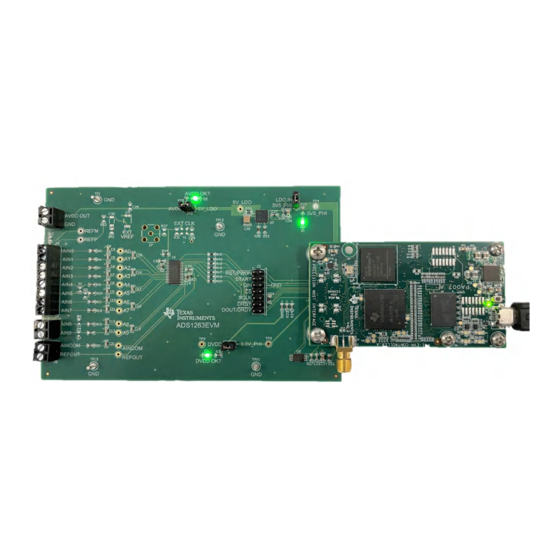
4. Connect external sensors to terminal blocks J3-J6 in accordance with the examples given in Section 3.1.2. Figure 7-1. ADS1263EVM Hardware Connections Figure 7-2. Launch the EVM GUI Software SBAU206B – APRIL 2015 – REVISED MAY 2023 ADS1263EVM-PDK Evaluation Module Submit Document Feedback Copyright © 2023 Texas Instruments Incorporated... -
Page 22: Evm Gui Global Settings For Adc Control
Value column, or by selecting from the drop-down menus in the Field View control. Figure 7-3. ADS1263EVM GUI Global Settings for the ADC Control Page ADS1263EVM-PDK Evaluation Module SBAU206B – APRIL 2015 – REVISED MAY 2023 Submit Document Feedback Copyright © 2023 Texas Instruments Incorporated... -
Page 23: Time Domain Display
Switching pages to any of the Analysis tools described in the subsequent sections causes calculations to be performed on the same set of data. Figure 7-4. ADS1263EVM GUI Time Domain Display Page SBAU206B – APRIL 2015 – REVISED MAY 2023 ADS1263EVM-PDK Evaluation Module Submit Document Feedback Copyright © 2023 Texas Instruments Incorporated... -
Page 24: Frequency Domain Display
32-bit ADC. The None option corresponds to not using a window (or using a rectangular window) and is not recommended. Figure 7-5. ADS1263EVM GUI Frequency Domain Display Page ADS1263EVM-PDK Evaluation Module SBAU206B – APRIL 2015 – REVISED MAY 2023 Submit Document Feedback Copyright © 2023 Texas Instruments Incorporated... -
Page 25: Histogram Display
ADC is reflected in the standard deviation of the ADC output code histogram that is obtained by performing multiple conversions of a dc input applied to a given channel. Figure 7-6. ADS1263EVM GUI Histogram Display Page SBAU206B – APRIL 2015 – REVISED MAY 2023 ADS1263EVM-PDK Evaluation Module Submit Document Feedback Copyright © 2023 Texas Instruments Incorporated... -
Page 26: Using The Gui To Control Adc2
See the ADC2 section of the ADS1263 data sheet for more information about how to configure and retrieve data from ADC2. ADS1263EVM-PDK Evaluation Module SBAU206B – APRIL 2015 – REVISED MAY 2023 Submit Document Feedback Copyright © 2023 Texas Instruments Incorporated... -
Page 27: Bill Of Materials, Pcb Layout, And Schematics
SH-JP1, SH-JP2, SH- SPC02SYAN Connector Shunt, 100mil, Flash Gold, Black Solutions TP1, TP11, TP12, 1573-2 Keystone Terminal, Turret, TH, Double TP13 SBAU206B – APRIL 2015 – REVISED MAY 2023 ADS1263EVM-PDK Evaluation Module Submit Document Feedback Copyright © 2023 Texas Instruments Incorporated... - Page 28 Thermistor NTC, 10.0k ohm, 1%, 0603 Texas REF7025QDGK, DGK0008A REF7025QDGKR Instruments (VSSOP-8) Abracon ASEMB-7.3728MHZ-XY-T OSC, 7.3728 MHz, 1.8 - 3.3V, SMD Corporation ADS1263EVM-PDK Evaluation Module SBAU206B – APRIL 2015 – REVISED MAY 2023 Submit Document Feedback Copyright © 2023 Texas Instruments Incorporated...
-
Page 29: Pcb Layout
8.2 PCB Layout Figure 8-1 shows the EVM printed circuit board (PCB) layout for the ADS1263EVM. Figure 8-1. ADS1263EVM PCB Layout SBAU206B – APRIL 2015 – REVISED MAY 2023 ADS1263EVM-PDK Evaluation Module Submit Document Feedback Copyright © 2023 Texas Instruments Incorporated... -
Page 30: Schematics
CAPN 49.9 ADC.CS REFOUT REFOUT AVSS BYPASS DGND ADS1263IPWR Figure 8-2. ADS1263EVM ADC, Analog Input, EEPROM, and Digital Interface Circuits ADS1263EVM-PDK Evaluation Module SBAU206B – APRIL 2015 – REVISED MAY 2023 Submit Document Feedback Copyright © 2023 Texas Instruments Incorporated... - Page 31 3.3V --> disconnect DVDD shunt to apply 6.65k 6.65k EXT Clock Green Green Figure 8-3. ADS1263EVM Power, Clock, and Voltage Reference Circuits SBAU206B – APRIL 2015 – REVISED MAY 2023 ADS1263EVM-PDK Evaluation Module Submit Document Feedback Copyright © 2023 Texas Instruments Incorporated...
-
Page 32: Revision History
Changes from Revision A (December 2015) to Revision B (May 2023) Page • Changed entire document to reflect changes made in EVM moving to a new platform........ADS1263EVM-PDK Evaluation Module SBAU206B – APRIL 2015 – REVISED MAY 2023 Submit Document Feedback Copyright © 2023 Texas Instruments Incorporated... - Page 33 STANDARD TERMS FOR EVALUATION MODULES Delivery: TI delivers TI evaluation boards, kits, or modules, including any accompanying demonstration software, components, and/or documentation which may be provided together or separately (collectively, an “EVM” or “EVMs”) to the User (“User”) in accordance with the terms set forth herein.
- Page 34 www.ti.com Regulatory Notices: 3.1 United States 3.1.1 Notice applicable to EVMs not FCC-Approved: FCC NOTICE: This kit is designed to allow product developers to evaluate electronic components, circuitry, or software associated with the kit to determine whether to incorporate such items in a finished product and software developers to write software applications for use with the end product.
- Page 35 www.ti.com Concernant les EVMs avec antennes détachables Conformément à la réglementation d'Industrie Canada, le présent émetteur radio peut fonctionner avec une antenne d'un type et d'un gain maximal (ou inférieur) approuvé pour l'émetteur par Industrie Canada. Dans le but de réduire les risques de brouillage radioélectrique à...
- Page 36 www.ti.com EVM Use Restrictions and Warnings: 4.1 EVMS ARE NOT FOR USE IN FUNCTIONAL SAFETY AND/OR SAFETY CRITICAL EVALUATIONS, INCLUDING BUT NOT LIMITED TO EVALUATIONS OF LIFE SUPPORT APPLICATIONS. 4.2 User must read and apply the user guide and other available documentation provided by TI regarding the EVM prior to handling or using the EVM, including without limitation any warning or restriction notices.
- Page 37 Notwithstanding the foregoing, any judgment may be enforced in any United States or foreign court, and TI may seek injunctive relief in any United States or foreign court. Mailing Address: Texas Instruments, Post Office Box 655303, Dallas, Texas 75265 Copyright © 2023, Texas Instruments Incorporated...
- Page 38 TI products. TI’s provision of these resources does not expand or otherwise alter TI’s applicable warranties or warranty disclaimers for TI products. TI objects to and rejects any additional or different terms you may have proposed. IMPORTANT NOTICE Mailing Address: Texas Instruments, Post Office Box 655303, Dallas, Texas 75265 Copyright © 2023, Texas Instruments Incorporated...
Need help?
Do you have a question about the ADS1263EVM-PDK and is the answer not in the manual?
Questions and answers