Table of Contents
Advertisement
Quick Links
ADS1256EVM and ADS1256EVM-PDK
This user's guide describes the characteristics, operation, and use of the ADS1256EVM, both by itself and
as part of the ADS1256EVM-PDK. This EVM is an evaluation fixture for the
(ΔΣ) analog-to-digital converter (ADC). It also serves as an evaluation platform for the ADS1255, which is
a proper subset of the ADS1256. It allows evaluation of all aspects of the ADS1256 device. A complete
circuit description, schematic diagram, and bill of materials are included.
The following related documents are available through the Texas Instruments web site at www.ti.com.
SBAU090E – November 2003 – Revised November 2018
Submit Documentation Feedback
Device
ADS1256
REF5025
OPA350
Copyright © 2003–2018, Texas Instruments Incorporated
SBAU090E – November 2003 – Revised November 2018
ADS1256
Literature Number
SBAS288
SBOS410
SBOS099
ADS1256EVM and ADS1256EVM-PDK
User's Guide
24-bit delta-sigma
1
Advertisement
Table of Contents

Related Manuals for Texas Instruments ADS1256EVM-PDK


Summary of Contents for Texas Instruments ADS1256EVM-PDK
- Page 1 SBAU090E – November 2003 – Revised November 2018 ADS1256EVM and ADS1256EVM-PDK This user's guide describes the characteristics, operation, and use of the ADS1256EVM, both by itself and as part of the ADS1256EVM-PDK. This EVM is an evaluation fixture for the ADS1256 24-bit delta-sigma (ΔΣ) analog-to-digital converter (ADC).
-
Page 2: Table Of Contents
Install New Driver Wizard Screen 4 ..................Install New Driver Wizard Screen 5 ..............USBStyx Driver Verification Using Device Manager ......ADS1256EVM-PDK Plug-In Averages, PGA Gain, and Effective Data Rate Controls ........................MUX Tab ........................Clocks Tab ........................GPIO Tab ...................... - Page 3 The MMB0 motherboard allows the ADS1256EVM to be connected to the computer via an available USB port. This manual shows how to use the MMB0 as part of the ADS1256EVM-PDK, but does not provide technical details on the MMB0 itself.
- Page 4 ADCPro is a program for collecting, recording, and analyzing data from ADC evaluation boards. It is based on a number of plug-in programs, so it can be expanded easily with new test and data collection plug-ins. The ADS1256EVM-PDK is controlled by a plug-in that runs in ADCPro. For more information about ADCPro, see the ADCPro™...
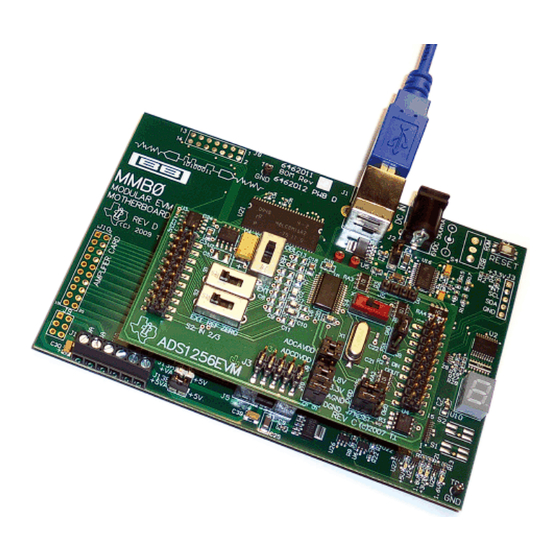
- Page 5 It can be connected to any Modular EVM System interface card. The ADS1256EVM is available as a stand-alone printed circuit board (PCB) or as part of the ADS1256EVM-PDK, which includes an MMB0 motherboard and software. As a stand-alone PCB, the ADS1256EVM is useful for prototyping designs and firmware.
-
Page 6: Evm Overview
REF– Input Inverting external reference input J1.20 SYSREFP REF+ Input Noninverting external reference input J1.9-J1.19 odd AGND Input Signal ground ADS1256EVM and ADS1256EVM-PDK SBAU090E – November 2003 – Revised November 2018 Submit Documentation Feedback Copyright © 2003–2018, Texas Instruments Incorporated... -
Page 7: Digital Interface
The GPIO pins for the ADS1256 are shown in Figure 2. These pins (from left to right) are D3 to D0. SBAU090E – November 2003 – Revised November 2018 ADS1256EVM and ADS1256EVM-PDK Submit Documentation Feedback Copyright © 2003–2018, Texas Instruments Incorporated... -
Page 8: Power Supplies
Positive digital supply J5.9 +3.3VD Positive digital supply, +3.3V Digital supply; select using J10 J5.10 +5VD Positive digital supply, +5V ADS1256EVM and ADS1256EVM-PDK SBAU090E – November 2003 – Revised November 2018 Submit Documentation Feedback Copyright © 2003–2018, Texas Instruments Incorporated... -
Page 9: Jumper Block
These pins select 3.3V for the digital supply voltage. If this selection is used, do not populate pins 5-6. 4.1.5 J10 Pins 3-4: DGND Select Shorting this jumper connects the ADS1256EVM ground net to DGND. SBAU090E – November 2003 – Revised November 2018 ADS1256EVM and ADS1256EVM-PDK Submit Documentation Feedback Copyright © 2003–2018, Texas Instruments Incorporated... -
Page 10: Switch S3
S3 appears on the board. A description of switch S3 is provided in Table Figure 4. Switch S3 ADS1256EVM and ADS1256EVM-PDK SBAU090E – November 2003 – Revised November 2018 Submit Documentation Feedback Copyright © 2003–2018, Texas Instruments Incorporated... -
Page 11: Switch S4
Table 7. System Clock Select Switch Board Marking Switch Position Clock Source XTAL Left Onboard 7.68MHz crystal Right External (J2 pin 17) SBAU090E – November 2003 – Revised November 2018 ADS1256EVM and ADS1256EVM-PDK Submit Documentation Feedback Copyright © 2003–2018, Texas Instruments Incorporated... -
Page 12: Switches S1 And S2
AIN0 Connection AIN1 Connection Left External J1.2 J1.1 Middle Reference voltage +2.5V AGND ZERO Right Zero (shorted to +2.5V +2.5V reference) ADS1256EVM and ADS1256EVM-PDK SBAU090E – November 2003 – Revised November 2018 Submit Documentation Feedback Copyright © 2003–2018, Texas Instruments Incorporated... -
Page 13: Ain2-3 Input Select Switch (S2)
HPA-MCU Interface boards available from Texas Instruments, or the MMB0 if purchased as part of the ADS1256EVM-PDK. For a list of compatible interface and/or accessory boards for the EVM or the ADS1256, see the relevant product folder on the TI web site. -
Page 14: Ads1256Evm Default Jumper And Switch Locations
SYNC/PDWN header connection RESET header connection CS header connection none +1.8VD connection 1-2, 3-4, and 4-5 +3.3VD, AGND, and DGND Cconnection ADS1256EVM and ADS1256EVM-PDK SBAU090E – November 2003 – Revised November 2018 Submit Documentation Feedback Copyright © 2003–2018, Texas Instruments Incorporated... -
Page 15: Default Switch Positions
ADS1256EVM-PDK Kit Operation This section provides information on using the ADS1256EVM-PDK, including setup, program installation, and program usage. To prepare to evaluate the ADS1256 with the ADS1256EVM-PDK, complete the following steps: Step 1. Install the ADCPro software (if not already installed). -
Page 16: Ads1256Evm-Pdk Setup Wizard
ADS1256EVM-PDK Kit Operation www.ti.com Figure 8. ADS1256EVM-PDK Setup Wizard Figure 9. ADS1256EVM-PDK License Agreement ADS1256EVM and ADS1256EVM-PDK SBAU090E – November 2003 – Revised November 2018 Submit Documentation Feedback Copyright © 2003–2018, Texas Instruments Incorporated... -
Page 17: Ads1256Evm-Pdk Installation In Progress
ADS1256EVM-PDK Kit Operation www.ti.com Figure 10. ADS1256EVM-PDK Installation in Progress Figure 11. ADS1256EVM-PDK Installation Complete SBAU090E – November 2003 – Revised November 2018 ADS1256EVM and ADS1256EVM-PDK Submit Documentation Feedback Copyright © 2003–2018, Texas Instruments Incorporated... -
Page 18: Mmb0 Initial Configuration
Software and Completing Driver Installation. Setting Up the ADS1256EVM-PDK The ADS1256EVM-PDK contains both the ADS1256EVM and the MMB0 motherboard; however, these devices are shipped unconnected. Follow these steps to set up the ADS1256EVM-PDK: Step 1. Unpack the ADS1256EVM-PDK kit. -
Page 19: Connecting The Ads1256Evm To The Mmb0
Set the reference source select switches S1 and S2 to the center position. • Set up jumper block J3 as shown; refer to Figure Figure 13. Connecting the ADS1256EVM to the MMB0 SBAU090E – November 2003 – Revised November 2018 ADS1256EVM and ADS1256EVM-PDK Submit Documentation Feedback Copyright © 2003–2018, Texas Instruments Incorporated... -
Page 20: Mmb0 Powered From Ac Adapter
The ADS1256EVM-PDK can be operated with a unipolar +5V supply or a bipolar ±5V supply. If the ADS1256EVM-PDK is to be operated in unipolar mode only, either an ac adapter or a lab power supply can be used. If the ADS1256EVM-PDK is to be operated in bipolar mode, a ±5V power supply must be connected;... -
Page 21: Mmb0 Configured For Lab Power Supply
+5V dc supply voltage to the +5VA terminal on J14 if the +5V/+5VA position on J13 is shorted. Figure 15. MMB0 Configured for Lab Power Supply SBAU090E – November 2003 – Revised November 2018 ADS1256EVM and ADS1256EVM-PDK Submit Documentation Feedback Copyright © 2003–2018, Texas Instruments Incorporated... -
Page 22: Ni-Visa Driver Installation Wizard, Screen
The program for evaluating the ADS1256EVM-PDK is called ADCPro. This program uses plug-ins to communicate with the EVM. The ADS1256EVM-PDK plug-in is included in the ADS1256EVM-PDK package. -
Page 23: Ni-Visa Driver Installation Wizard, Screen
ADS1256EVM-PDK Kit Operation www.ti.com Figure 17. NI-VISA Driver Installation Wizard, Screen 2 Figure 18. NI-VISA Driver Installation Wizard, Screen 3 SBAU090E – November 2003 – Revised November 2018 ADS1256EVM and ADS1256EVM-PDK Submit Documentation Feedback Copyright © 2003–2018, Texas Instruments Incorporated... -
Page 24: Ni-Visa Driver Installation Wizard, Screen 4
ADS1256EVM-PDK Kit Operation www.ti.com Figure 19. NI-VISA Driver Installation Wizard, Screen 4 ADS1256EVM and ADS1256EVM-PDK SBAU090E – November 2003 – Revised November 2018 Submit Documentation Feedback Copyright © 2003–2018, Texas Instruments Incorporated... -
Page 25: Ni-Visa Driver Verification Using Device Manager
1. Start the software by selecting ADCPro from the Windows Start menu. The screen shown in Figure 21 appears. Figure 21. ADCPro Software Start-up Display Window SBAU090E – November 2003 – Revised November 2018 ADS1256EVM and ADS1256EVM-PDK Submit Documentation Feedback Copyright © 2003–2018, Texas Instruments Incorporated... -
Page 26: Ads1256Evm-Pdk Plug-In Display Window
Figure 22. ADS1256EVM-PDK Plug-In Display Window 3. The ADS1256EVM-PDK plug-in window has a status area at the top of the screen. When the plug-in is first loaded, the plug-in searches for the board. You will see a series of messages in the status area indicating this action. -
Page 27: Install New Driver Wizard Screen 1
ADS1256EVM-PDK Kit Operation www.ti.com Figure 23. Install New Driver Wizard Screen 1 Figure 24. Install New Driver Wizard Screen 2 SBAU090E – November 2003 – Revised November 2018 ADS1256EVM and ADS1256EVM-PDK Submit Documentation Feedback Copyright © 2003–2018, Texas Instruments Incorporated... - Page 28 ADS1256EVM-PDK Kit Operation www.ti.com Figure 25. Install New Driver Wizard Screen 3 Figure 26. Install New Driver Wizard Screen 4 ADS1256EVM and ADS1256EVM-PDK SBAU090E – November 2003 – Revised November 2018 Submit Documentation Feedback Copyright © 2003–2018, Texas Instruments Incorporated...
-
Page 29: Usbstyx Driver Verification Using Device Manager
Figure 28. USBStyx Driver Verification Using Device Manager The driver installation wizard sequence should not appear again, unless you connect the board to a different USB port SBAU090E – November 2003 – Revised November 2018 ADS1256EVM and ADS1256EVM-PDK Submit Documentation Feedback Copyright © 2003–2018, Texas Instruments Incorporated... -
Page 30: Ads1256Evm-Pdk Plug-In Averages, Pga Gain, And Effective Data Rate Controls
Only one of each kind of plug-in can be loaded at a time. If you select a different plug-in, the previous plug-in is unloaded. Using the ADS1256EVM-PDK Plug-in The ADS1256EVM-PDK plug-in for ADCPro provides complete control over all settings of the ADS1256. It consists of a tabbed interface (see Figure 22), with different functions available on different tabs. -
Page 31: Mux Tab
S2, selects the measurement for the inputs applied to the analog interface J1. The MUX tab is shown Figure Figure 30. MUX Tab SBAU090E – November 2003 – Revised November 2018 ADS1256EVM and ADS1256EVM-PDK Submit Documentation Feedback Copyright © 2003–2018, Texas Instruments Incorporated... -
Page 32: Clocks Tab
Clock Out Rate pull-down menu. There are options to set CLKOUT to f /2, f /4, or to turn it off. CLKIN CLKIN CLKIN Figure 31. Clocks Tab ADS1256EVM and ADS1256EVM-PDK SBAU090E – November 2003 – Revised November 2018 Submit Documentation Feedback Copyright © 2003–2018, Texas Instruments Incorporated... -
Page 33: Gpio Tab
Figure 32 illustrates the GPIO tab. Figure 32. GPIO Tab SBAU090E – November 2003 – Revised November 2018 ADS1256EVM and ADS1256EVM-PDK Submit Documentation Feedback Copyright © 2003–2018, Texas Instruments Incorporated... -
Page 34: Power & Ref Tab
Standby. Pressing the Wakeup button releases the ADS1256 from this mode. The Power & Ref tab is illustrated in Figure Figure 33. Power & Ref Tab ADS1256EVM and ADS1256EVM-PDK SBAU090E – November 2003 – Revised November 2018 Submit Documentation Feedback Copyright © 2003–2018, Texas Instruments Incorporated... -
Page 35: Cal Tab
Read button reads the current calibration register value. Figure 34. Cal Tab SBAU090E – November 2003 – Revised November 2018 ADS1256EVM and ADS1256EVM-PDK Submit Documentation Feedback Copyright © 2003–2018, Texas Instruments Incorporated... -
Page 36: Evm Software About Tab
The Notes indicator may show relevant notes about the plug-in or firmware code, if there are any. Figure 35. EVM Software About Tab ADS1256EVM and ADS1256EVM-PDK SBAU090E – November 2003 – Revised November 2018 Submit Documentation Feedback Copyright © 2003–2018, Texas Instruments Incorporated... -
Page 37: Software Progress Indicator
Once you have configured the ADS1256 for your test scenario, pressing the ADCPro Acquire button starts the collection of the number of datapoints specified in the Test plug-in Block Size control. The ADS1256EVM-PDK plug-in disables all the front panel controls while acquiring, and displays a progress bar as shown in Figure Figure 36. -
Page 38: Ads1256Evm Bill Of Materials
SNT-100-BK-T C5, C6, C8, C9, C11, Installed C12,C13, C14, C15, C16, C17 1×2 Position header, 0.1” Samtec TSW-102-07-L-S Installed spacing ADS1256EVM and ADS1256EVM-PDK SBAU090E – November 2003 – Revised November 2018 Submit Documentation Feedback Copyright © 2003–2018, Texas Instruments Incorporated... -
Page 39: Ads1256Evm Pcb: Top-Side Image
Figure 37. ADS1256EVM PCB: Top-Side Image Figure 38. ADS1256EVM PCB: Layer 1 Figure 39. ADS1256EVM PCB: Layer 2 Figure 40. ADS1256EVM PCB: Bottom-Side Image SBAU090E – November 2003 – Revised November 2018 ADS1256EVM and ADS1256EVM-PDK Submit Documentation Feedback Copyright © 2003–2018, Texas Instruments Incorporated... -
Page 40: Schematic
+3.3VD +5VD POWERHDR C4: 100UF LOW ESR TANTALUM KEMET "KO-CAP" T520D107M010AS4350 C5: 22UF MLCC MURATA KEMET PANASONIC Figure 41. Schematic ADS1256EVM and ADS1256EVM-PDK SBAU090E – November 2003 – Revised November 2018 Submit Documentation Feedback Copyright © 2003–2018, Texas Instruments Incorporated... - Page 41 ..........• Updated software download links in the Installing the ADCPro Software section.............. • Added External Wall-Adapter Power-Supply Requirements section. SBAU090E – November 2003 – Revised November 2018 Revision History Submit Documentation Feedback Copyright © 2003–2018, Texas Instruments Incorporated...
- Page 42 STANDARD TERMS FOR EVALUATION MODULES Delivery: TI delivers TI evaluation boards, kits, or modules, including any accompanying demonstration software, components, and/or documentation which may be provided together or separately (collectively, an “EVM” or “EVMs”) to the User (“User”) in accordance with the terms set forth herein.
- Page 43 FCC Interference Statement for Class B EVM devices NOTE: This equipment has been tested and found to comply with the limits for a Class B digital device, pursuant to part 15 of the FCC Rules. These limits are designed to provide reasonable protection against harmful interference in a residential installation.
- Page 44 【無線電波を送信する製品の開発キットをお使いになる際の注意事項】 開発キットの中には技術基準適合証明を受けて いないものがあります。 技術適合証明を受けていないもののご使用に際しては、電波法遵守のため、以下のいずれかの 措置を取っていただく必要がありますのでご注意ください。 1. 電波法施行規則第6条第1項第1号に基づく平成18年3月28日総務省告示第173号で定められた電波暗室等の試験設備でご使用 いただく。 2. 実験局の免許を取得後ご使用いただく。 3. 技術基準適合証明を取得後ご使用いただく。 なお、本製品は、上記の「ご使用にあたっての注意」を譲渡先、移転先に通知しない限り、譲渡、移転できないものとします。 上記を遵守頂けない場合は、電波法の罰則が適用される可能性があることをご留意ください。 日本テキサス・イ ンスツルメンツ株式会社 東京都新宿区西新宿6丁目24番1号 西新宿三井ビル 3.3.3 Notice for EVMs for Power Line Communication: Please see http://www.tij.co.jp/lsds/ti_ja/general/eStore/notice_02.page 電力線搬送波通信についての開発キットをお使いになる際の注意事項については、次のところをご覧ください。http:/ /www.tij.co.jp/lsds/ti_ja/general/eStore/notice_02.page 3.4 European Union 3.4.1 For EVMs subject to EU Directive 2014/30/EU (Electromagnetic Compatibility Directive): This is a class A product intended for use in environments other than domestic environments that are connected to a low-voltage power-supply network that supplies buildings used for domestic purposes.
- Page 45 Notwithstanding the foregoing, any judgment may be enforced in any United States or foreign court, and TI may seek injunctive relief in any United States or foreign court. Mailing Address: Texas Instruments, Post Office Box 655303, Dallas, Texas 75265 Copyright © 2018, Texas Instruments Incorporated...
- Page 46 TI products. TI’s provision of these resources does not expand or otherwise alter TI’s applicable warranties or warranty disclaimers for TI products. Mailing Address: Texas Instruments, Post Office Box 655303, Dallas, Texas 75265 Copyright © 2018, Texas Instruments Incorporated...
Need help?
Do you have a question about the ADS1256EVM-PDK and is the answer not in the manual?
Questions and answers