Table of Contents
Advertisement
Quick Links
www.ti.com
User's Guide
ADS1258EVM-PDK Evaluation Module
This user's guide describes the characteristics, operation, and use of the
This EVM is an evaluation platform for the ADS1258, a 24-bit, 125-kSPS, 16-channel (multiplexed), delta-sigma
(ΔΣ) analog-to-digital converter (ADC). The ADS1258 offers excellent noise performance, fast sampling speeds,
a programmable channel sequencer, and access to the multiplexer output for efficient signal conditioning. The
ADS1258EVM eases the evaluation of the device with hardware, software, and computer connectivity through
the universal serial bus (USB) interface. This user's guide includes complete circuit descriptions, schematic
diagrams, and a bill of materials. Throughout this document, the abbreviation EVM and the term evaluation
module are synonymous with the ADS1258EVM.
The ADS1258EVM and software can also support the 16-bit
must manually remove the ADS1258 and install the ADS1158. See
ADS1258 on the EVM. The ADS1158 is not discussed further in this document.
SBAU126E – MAY 2007 – REVISED JUNE 2023
Submit Document Feedback
ABSTRACT
Note
Copyright © 2023 Texas Instruments Incorporated
ADS1258
evaluation module (EVM).
ADS1158
device. However, the user
Section 8.3
for the location of the
ADS1258EVM-PDK Evaluation Module
1
Advertisement
Table of Contents

Related Manuals for Texas Instruments ADS1258EVM-PDK


Summary of Contents for Texas Instruments ADS1258EVM-PDK
- Page 1 Section 8.3 for the location of the ADS1258 on the EVM. The ADS1158 is not discussed further in this document. SBAU126E – MAY 2007 – REVISED JUNE 2023 ADS1258EVM-PDK Evaluation Module Submit Document Feedback Copyright © 2023 Texas Instruments Incorporated...
-
Page 2: Table Of Contents
® ® Microsoft and Windows are registered trademarks of Microsoft Corporation. All trademarks are the property of their respective owners. ADS1258EVM-PDK Evaluation Module SBAU126E – MAY 2007 – REVISED JUNE 2023 Submit Document Feedback Copyright © 2023 Texas Instruments Incorporated... -
Page 3: Ads1258Evm Overview
3.3-V ADC digital voltage (DVDD) supplied by PHI controller, or use external voltage supply • Test points for power, GND, reference, and all digital signals to and from the PHI controller SBAU126E – MAY 2007 – REVISED JUNE 2023 ADS1258EVM-PDK Evaluation Module Submit Document Feedback Copyright © 2023 Texas Instruments Incorporated... -
Page 4: Getting Started With The Ads1258Evm
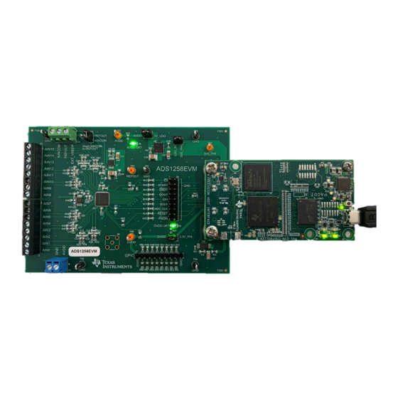
EVM and the corresponding GUI. Links are provided to navigate from this quick-start guide to the appropriate section at each applicable step. 1. Remove the ADS1258EVM, PHI board, and USB cable from the ADS1258EVM-PDK box. 2. If necessary, connect the PHI board to the ADS1258EVM (see Figure 7-1). -
Page 5: Analog Interface
Conversely, do not use AIN1 and AIN2 as a differential pair because there is no capacitor connecting these two inputs. SBAU126E – MAY 2007 – REVISED JUNE 2023 ADS1258EVM-PDK Evaluation Module Submit Document Feedback Copyright © 2023 Texas Instruments Incorporated... -
Page 6: Adc Connections And Decoupling
ADCINN PLLCAP MUXOUTP MUXOUTP MUXOUTN MUXOUTN AVSS DGND ADS1258IRTCR Figure 3-2. ADS1258EVM ADC Power-Supply Decoupling and Analog and Digital Connections ADS1258EVM-PDK Evaluation Module SBAU126E – MAY 2007 – REVISED JUNE 2023 Submit Document Feedback Copyright © 2023 Texas Instruments Incorporated... -
Page 7: Configurable Multiplexer Loop
Implement a pseudo-differential measurement on the ADS1258EVM by shorting the 2.5-V REFOUT voltage to the appropriate channel. In Auto-Scan mode, use jumper JP2 to short REFOUT to AINCOM because AINCOM SBAU126E – MAY 2007 – REVISED JUNE 2023 ADS1258EVM-PDK Evaluation Module Submit Document Feedback Copyright © 2023 Texas Instruments Incorporated... -
Page 8: Clocking
See the ADS1258 data sheet for information about the allowable clock frequency range. EXT Clock ADC.MCLK_OUT 49.9 Figure 3-5. ADS1258EVM Clock Circuit ADS1258EVM-PDK Evaluation Module SBAU126E – MAY 2007 – REVISED JUNE 2023 Submit Document Feedback Copyright © 2023 Texas Instruments Incorporated... -
Page 9: Voltage Reference
EXT_VREFP to make sure that the reference voltage can still be used to bias external circuitry. See the ADS1258 data sheet for information about the allowable voltage range on the VREFx pins. SBAU126E – MAY 2007 – REVISED JUNE 2023 ADS1258EVM-PDK Evaluation Module Submit Document Feedback Copyright © 2023 Texas Instruments Incorporated... -
Page 10: Digital Interface
DVDD 49.9 GPIO1 49.9 GPIO0 100k 100k 100k 100k 100k 100k 100k 100k Figure 4-2. ADS1258EVM GPIO Circuit and Header ADS1258EVM-PDK Evaluation Module SBAU126E – MAY 2007 – REVISED JUNE 2023 Submit Document Feedback Copyright © 2023 Texas Instruments Incorporated... -
Page 11: Power Supplies
ADS1258EVM schematic that includes the LEDs and test points. AVDD DVDD AVDD DVDD 6.65k 6.65k Green Green Figure 5-2. ADS1258EVM AVDD and DVDD Indicator LEDs SBAU126E – MAY 2007 – REVISED JUNE 2023 ADS1258EVM-PDK Evaluation Module Submit Document Feedback Copyright © 2023 Texas Instruments Incorporated... -
Page 12: Software Installation
6-1, accept the license agreements and follow the on-screen instructions to complete the installation. Figure 6-1. Software Installation and Prompts ADS1258EVM-PDK Evaluation Module SBAU126E – MAY 2007 – REVISED JUNE 2023 Submit Document Feedback Copyright © 2023 Texas Instruments Incorporated... - Page 13 Figure 6-3, if not already installed. Figure 6-3. LabVIEW Run-Time Engine Installation SBAU126E – MAY 2007 – REVISED JUNE 2023 ADS1258EVM-PDK Evaluation Module Submit Document Feedback Copyright © 2023 Texas Instruments Incorporated...
-
Page 14: Evm Operation And Gui
Figure 7-1. ADS1258EVM Hardware Connections Figure 7-2. Launch the EVM GUI Software ADS1258EVM-PDK Evaluation Module SBAU126E – MAY 2007 – REVISED JUNE 2023 Submit Document Feedback Copyright © 2023 Texas Instruments Incorporated... -
Page 15: Evm Gui Global Settings For Adc Control
Value column, or by selecting from the drop-down menus in the Field View control. Figure 7-3. ADS1258EVM GUI Global Settings for ADC Control Page SBAU126E – MAY 2007 – REVISED JUNE 2023 ADS1258EVM-PDK Evaluation Module Submit Document Feedback Copyright © 2023 Texas Instruments Incorporated... -
Page 16: Time-Domain Display
Switching pages to any of the Analysis tools described in the subsequent sections causes calculations to be performed on the same set of data. Figure 7-4. ADS1258EVM GUI Time Domain Display Page ADS1258EVM-PDK Evaluation Module SBAU126E – MAY 2007 – REVISED JUNE 2023 Submit Document Feedback Copyright © 2023 Texas Instruments Incorporated... -
Page 17: Frequency-Domain Display
24-bit ADC. The None option corresponds to not using a window (or using a rectangular window) and is not recommended. Figure 7-5. ADS1258EVM GUI Frequency Domain Display Page SBAU126E – MAY 2007 – REVISED JUNE 2023 ADS1258EVM-PDK Evaluation Module Submit Document Feedback Copyright © 2023 Texas Instruments Incorporated... -
Page 18: Histogram Display
ADC is reflected in the standard deviation of the ADC output code histogram that is obtained by performing multiple conversions of a dc input applied to a given channel. Figure 7-6. ADS1258EVM GUI Histogram Display Page ADS1258EVM-PDK Evaluation Module SBAU126E – MAY 2007 – REVISED JUNE 2023 Submit Document Feedback Copyright © 2023 Texas Instruments Incorporated... -
Page 19: Bill Of Materials, Layout, And Schematics
19.7mil, 30x2, SMT Header, 100mil, 9x2, 9x2 Header TSW-109-07-G-D Samtec Gold, TH Header, 100mil, 10x1, 10x1 Header TSW-110-07-G-S Samtec Gold, TH SBAU126E – MAY 2007 – REVISED JUNE 2023 ADS1258EVM-PDK Evaluation Module Submit Document Feedback Copyright © 2023 Texas Instruments Incorporated... - Page 20 Multipurpose, Black, 5011 Keystone Electronics Testpoint Test Point, Orange Multipurpose TP3, TP4, TP5, TP7 Multipurpose, 5013 Keystone Electronics Testpoint Orange, TH ADS1258EVM-PDK Evaluation Module SBAU126E – MAY 2007 – REVISED JUNE 2023 Submit Document Feedback Copyright © 2023 Texas Instruments Incorporated...
- Page 21 Amphenol RF Gold, 50 Ohm, TH RES, 0, 5%, 0.1 W, R2, R7, R30 AEC-Q200 Grade 0, 0603 ERJ-3GEY0R00V Panasonic 0603 SBAU126E – MAY 2007 – REVISED JUNE 2023 ADS1258EVM-PDK Evaluation Module Submit Document Feedback Copyright © 2023 Texas Instruments Incorporated...
-
Page 22: Evm Pcb Layout
8.2 EVM PCB Layout Figure 8-1 shows the EVM printed circuit board (PCB) layout for the ADS1258EVM. Figure 8-1. ADS1258EVM PCB Layout ADS1258EVM-PDK Evaluation Module SBAU126E – MAY 2007 – REVISED JUNE 2023 Submit Document Feedback Copyright © 2023 Texas Instruments Incorporated... -
Page 23: Schematics
ADS1258IRTCR 10uF START DRDY DOUT SCLK MCLK_OUT RESET PWDN Figure 8-2. ADS1258EVM ADC, Voltage Reference, EEPROM, and Digital Interface Circuits SBAU126E – MAY 2007 – REVISED JUNE 2023 ADS1258EVM-PDK Evaluation Module Submit Document Feedback Copyright © 2023 Texas Instruments Incorporated... - Page 24 100k 100k 100k 100k 100k 100k 47pF 47pF 1.00k 1.00k Figure 8-3. ADS1258EVM Analog Input, Multiplexer Loop, and GPIO Circuits ADS1258EVM-PDK Evaluation Module SBAU126E – MAY 2007 – REVISED JUNE 2023 Submit Document Feedback Copyright © 2023 Texas Instruments Incorporated...
- Page 25 AVDD AVDD DVDD AVDD_PWR AVDD_OUT 6.65k 6.65k Green Green 3.3V EVM_DVDD DVDD DVDD_PWR Figure 8-4. ADS1258EVM Power and Clock Circuits SBAU126E – MAY 2007 – REVISED JUNE 2023 ADS1258EVM-PDK Evaluation Module Submit Document Feedback Copyright © 2023 Texas Instruments Incorporated...
-
Page 26: Revision History
Changes from Revision D (May 2016) to Revision E (June 2023) Page • Changed entire document to reflect changes made in EVM moving to a new platform........ADS1258EVM-PDK Evaluation Module SBAU126E – MAY 2007 – REVISED JUNE 2023 Submit Document Feedback Copyright © 2023 Texas Instruments Incorporated... - Page 27 STANDARD TERMS FOR EVALUATION MODULES Delivery: TI delivers TI evaluation boards, kits, or modules, including any accompanying demonstration software, components, and/or documentation which may be provided together or separately (collectively, an “EVM” or “EVMs”) to the User (“User”) in accordance with the terms set forth herein.
- Page 28 www.ti.com Regulatory Notices: 3.1 United States 3.1.1 Notice applicable to EVMs not FCC-Approved: FCC NOTICE: This kit is designed to allow product developers to evaluate electronic components, circuitry, or software associated with the kit to determine whether to incorporate such items in a finished product and software developers to write software applications for use with the end product.
- Page 29 www.ti.com Concernant les EVMs avec antennes détachables Conformément à la réglementation d'Industrie Canada, le présent émetteur radio peut fonctionner avec une antenne d'un type et d'un gain maximal (ou inférieur) approuvé pour l'émetteur par Industrie Canada. Dans le but de réduire les risques de brouillage radioélectrique à...
- Page 30 www.ti.com EVM Use Restrictions and Warnings: 4.1 EVMS ARE NOT FOR USE IN FUNCTIONAL SAFETY AND/OR SAFETY CRITICAL EVALUATIONS, INCLUDING BUT NOT LIMITED TO EVALUATIONS OF LIFE SUPPORT APPLICATIONS. 4.2 User must read and apply the user guide and other available documentation provided by TI regarding the EVM prior to handling or using the EVM, including without limitation any warning or restriction notices.
- Page 31 Notwithstanding the foregoing, any judgment may be enforced in any United States or foreign court, and TI may seek injunctive relief in any United States or foreign court. Mailing Address: Texas Instruments, Post Office Box 655303, Dallas, Texas 75265 Copyright © 2023, Texas Instruments Incorporated...
- Page 32 TI products. TI’s provision of these resources does not expand or otherwise alter TI’s applicable warranties or warranty disclaimers for TI products. TI objects to and rejects any additional or different terms you may have proposed. IMPORTANT NOTICE Mailing Address: Texas Instruments, Post Office Box 655303, Dallas, Texas 75265 Copyright © 2023, Texas Instruments Incorporated...
Need help?
Do you have a question about the ADS1258EVM-PDK and is the answer not in the manual?
Questions and answers