Table of Contents
Advertisement
Quick Links
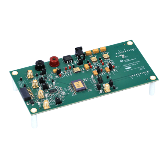
ADS1282-SP Evaluation Module (ADS1282EVM-CVAL)
This user's guide provides an overview of the evaluation module (EVM) including hardware and software
features and functions to be considered while using this module. This manual is applicable to the
ADS1282-SP EVM which is synonymous with ADS1282EVM-CVAL, the orderable part number. The EVM
provides a platform for evaluating the ADC under various signal and clock configurations.
1
2
3
4
4.1
4.2
5
5.1
5.2
5.3
5.4
5.5
5.6
6
6.1
6.2
6.3
6.4
6.5
6.6
7
8
.......................................................................................................................
Appendix A
1
2
3
4
5
6
7
8
9
10
11
12
LaunchPad is a trademark of Texas Instruments.
All other trademarks are the property of their respective owners.
SBAU274 - July 2016
Submit Documentation Feedback
Contents
...............................................................................
..................................................................................
......................................................................................
...........................................................................................
................................................................................
.....................................................................................
.....................................................................
......................................................................
..................................................................................
.......................................................................................
....................................................................................
........................................................................................
..................................................................................................
......................................................................................................
................................................................................................
................................................................................................
....................................................................................................
............................................................................................
.............................................................................
List of Figures
...........................................................................
...............................................................................
...............................................................................................
......................................................................................
..............................................................................
..............................................................................
..............................................................................
............................................................................
................................................................................
Copyright © 2016, Texas Instruments Incorporated
.................................................
......................................................................
....................................................................
..................................................................
...........................................................
..................................................................
ADS1282-SP Evaluation Module (ADS1282EVM-CVAL)
User's Guide
SBAU274 - July 2016
3
3
3
5
5
6
13
13
14
14
14
15
16
17
17
19
24
25
31
33
34
37
40
3
4
5
6
6
7
8
9
10
11
12
13
1
Advertisement
Table of Contents

Related Manuals for Texas Instruments ADS1282-SP


Summary of Contents for Texas Instruments ADS1282-SP
-
Page 1: Table Of Contents
This manual is applicable to the ADS1282-SP EVM which is synonymous with ADS1282EVM-CVAL, the orderable part number. The EVM provides a platform for evaluating the ADC under various signal and clock configurations. - Page 2 ADS1282-SP GUI Quick Start STEP-3 ................... ADS1282-SP GUI Quick Start Step-3 .................. ADS1282-SP GUI Quick Start STEP-4 ................. ADS1282-SP GUI Quick Start Show All Steps ..................ADS1282-SP GUI Settings Page ..................ADS1282-SP GUI Data Capture ................... ADS1282-SP Data Capture Zooming ...................
-
Page 3: Ads1282-Sp Evm (Ads1282Evm-Cval)
Figure 2. As stated in this file, data capture from the ADS1282-SP EVM to the MSP430 EVM is not possible until the correct firmware is flashed into the MSP430 LaunchPad. Refer to the MSP430FR5969 LaunchPad Firmware Flashing Guide for ADS1282-SP (SBAC149) for full instructions. -
Page 4: Ads1282-Sp Software Gui Readme File
Flashing MSP430FR5969 LaunchPad with ADS1282-SP Firmware www.ti.com Figure 2. ADS1282-SP Software GUI README File ADS1282-SP Evaluation Module (ADS1282EVM-CVAL) SBAU274 – July 2016 Submit Documentation Feedback Copyright © 2016, Texas Instruments Incorporated... -
Page 5: Ads1282-Sp Setup And Quick Test
(A) With care, mate connectors J21 and J22 of the ADS1282EVM-CVAL to connectors J5 and J4 of the MSP430FR5969, respectively. (B) Provide power to the ADS1282-SP EVM connecting either • A 12 V AC/DC adaptor to connector J1, or •... -
Page 6: Ads1282-Sp Gui Setup
ADS1282-SP Setup and Quick Test www.ti.com ADS1282-SP GUI Setup Launch the ADS1282-SP GUI by double clicking the icon created on the desktop during installation. Figure 4. ADS1282-SP EVM GUI Icon The home page of the GUI appears (see Figure 5). The green Connected button will appear if all of the following is true: 1. -
Page 7: Ads1282-Sp Evm Gui Quick Start Step 1
ADS1282-SP Setup and Quick Test www.ti.com Complete STEP-1 of the Quick Start page by clicking the Reset device button followed by the Next button. Figure 6. ADS1282-SP EVM GUI Quick Start Step 1 SBAU274 – July 2016 ADS1282-SP Evaluation Module (ADS1282EVM-CVAL) Submit Documentation Feedback... -
Page 8: Ads1282-Sp Evm Gui Quick Start Step 2
Complete STEP-2 of the Quick Start page by leaving the Device Clock Selection as the default setting and clicking the Next button. Figure 7. ADS1282-SP EVM GUI Quick Start Step 2 ADS1282-SP Evaluation Module (ADS1282EVM-CVAL) SBAU274 – July 2016 Submit Documentation Feedback Copyright ©... -
Page 9: Ads1282-Sp Evm Gui Quick Start Step 3
Complete STEP-3 of the Quick Start page by leaving the Filter and Data Selection configuration as the default setting and clicking the Next button. Figure 8. ADS1282-SP EVM GUI Quick Start Step 3 SBAU274 – July 2016 ADS1282-SP Evaluation Module (ADS1282EVM-CVAL) Submit Documentation Feedback Copyright ©... -
Page 10: Ads1282-Sp Evm Gui Quick Start Step 4
Complete STEP-4 of the Quick Start page by leaving the MUX and PGA Gain Selection configuration as the default setting and clicking the Go To Data Capture button. Figure 9. ADS1282-SP EVM GUI Quick Start Step 4 ADS1282-SP Evaluation Module (ADS1282EVM-CVAL) SBAU274 –... -
Page 11: Ads1282-Sp Evm Gui Data Capture Frequency Domain
(SNR) in dBFS. In the following example, the 1 Nyquist integrated SNR is 123.71 dBFs, very close to the typical datasheet value of 124 dBFs for this device configuration. Figure 10. ADS1282-SP EVM GUI Data Capture Frequency Domain SBAU274 – July 2016 ADS1282-SP Evaluation Module (ADS1282EVM-CVAL) Submit Documentation Feedback Copyright ©... -
Page 12: Ads1282-Sp Evm Gui Data Capture Time Domain
11. The zoom function is achieved by clicking and holding the mouse button on the plot and dragging the mouse to vertical or horizontal zoom extents. NOTE: Although the ADS1282-SP is designed to handle a 5-Vpp differential analog input, the analog front end of this EVM is limited by the OPA1632 amplifier. Because only unipolar power was used to bias this amplifier, the OPA1632 inputs are limited to 4-Vpp differential with a common mode voltage of 2.5 V. -
Page 13: Ads1282-Sp Evm Detailed Description
ADS1282-SP EVM Detailed Description www.ti.com For convenience of changing ADS1282-SP configurations quickly, click the Show All Steps link at the bottom of the Quick Start page to see all the controls in one view, as shown in Figure Figure 12. ADS1282-SP EVM GUI Show All Steps ADS1282-SP EVM Detailed Description The following sub-sections describe the ADS1282-SP EVM in detail. -
Page 14: Ads1282-Sp Analog Inputs
On the EVM, MFLAG can be monitored at TP11 and also with LED D3. ADS1282-SP EVM Header Configuration The ADS1282-SP EVM is flexible in its configurability through the use of 2- and 3-pin headers. The default configuration of the EVM is set to facilitate initial testing by requiring no changes. -
Page 15: Ads1282-Sp Evm Test Points
ADS1282-SP EVM Detailed Description www.ti.com Figure 14. ADS1282-SP EVM Default Header Configuration ADS1282-SP EVM Test Points Table 2 lists all test points on the ADS1282-SP EVM. Table 2. ADS1282-SP EVM Test Points Description Test Point Silk Screen Schematic Page Description... -
Page 16: Ads1282-Sp Evm Layout
ADS1282-SP EVM Detailed Description www.ti.com Table 2. ADS1282-SP EVM Test Points Description (continued) Test Point Silk Screen Schematic Page Description TP23 VCCM1 Analog Common Mode Node of Channel 1 TP24 AUX_REFP Analog ADC REFP from J10 TP25 VOCM Analog REF5025 2.5-V Output... -
Page 17: Ads1282-Sp Gui Software In Detail
The Introduction page is the starting point for the GUI when launched and appears as shown in Figure If an ADS1282-SP EVM is powered and connected to an MSP430 LaunchPad that has the correct firmware loaded, then the green Connected button will appear. The top half of the Introduction page provides key features of the device as well as a functional block diagram when pressing Learn More. -
Page 18: Ads1282-Sp Gui Top-Most Border
ADS1282-SP GUI Software in Detail www.ti.com Figure 16. ADS1282-SP GUI Top-Most Border The left-most border contains icon links to the six pages of the GUI. The selected icon is highlighted to indicate what page is presently being displayed. Figure 17. ADS1282-SP GUI Left-Most Border ADS1282-SP Evaluation Module (ADS1282EVM-CVAL) SBAU274 –... -
Page 19: Quick Start Page
The first time the GUI is used, this page defaults to a step-by-step process. This step-by-step process can be bypassed by clicking the Show All Steps link. Figure 19. ADS1282-SP GUI Quick Start STEP-1 STEP-2 of the Quick Start page is Device Clock Selection as shown in Figure 20. -
Page 20: Ads1282-Sp Gui Quick Start Step-2
4.096-MHz crystal oscillator. By hovering over the picture with the mouse, the graphic is enlarged showing the jumper locations needed for the selected clock configuration. Figure 20. ADS1282-SP GUI Quick Start STEP-2 ADS1282-SP Evaluation Module (ADS1282EVM-CVAL) SBAU274 – July 2016 Submit Documentation Feedback Copyright ©... -
Page 21: Ads1282-Sp Gui Quick Start Step-2
The desired frequency is entered and is constrained to values between 1000 kHz and 4096 kHz. Any value entered outside this range will default to this min or max value. Figure 22. ADS1282-SP GUI Quick Start Step 2 SBAU274 – July 2016... -
Page 22: Ads1282-Sp Gui Quick Start Step-3
SINC+FIR LPF at 1000 SPS with the FIR LPF phase set to Linear Phase. Figure 23. ADS1282-SP GUI Quick Start STEP-3 The Digital Filter control determines what other controls become visible and active. As an example, if the... -
Page 23: Ads1282-Sp Gui Quick Start Step-4
Once a user is familiar with the GUI and device, it is convenient to display all controls of the Quick Start page in one view. This is achieved by clicking the link Show All Steps at the bottom of the page. Figure 26. ADS1282-SP GUI Quick Start Show All Steps SBAU274 – July 2016... -
Page 24: Settings Page
In applications, it is recommended to latch a low to high transition on this signal to set a flag that saturation has occurred. Both Power Down PWDN and RESET inputs can be manually controlled from the GPIO controls section. Figure 27. ADS1282-SP GUI Settings Page ADS1282-SP Evaluation Module (ADS1282EVM-CVAL) SBAU274 – July 2016 Submit Documentation Feedback Copyright ©... -
Page 25: Data Capture Page
The two modes of graphing, (1) Time Domain and (2) Frequency Domain, are selected by clicking the link above the graph with the same name. Figure 28. ADS1282-SP GUI Data Capture The Data Capture page, shown in Figure 28, is where captured data is displayed and analyzed. -
Page 26: Ads1282-Sp Data Capture Zooming
Figure 29 Figure Press the Red Reset button in upper right corner of graph to remove zoom functions. Figure 29. ADS1282-SP Data Capture Zooming Figure 30. ADS1282-SP Data Capture Zooming ADS1282-SP Evaluation Module (ADS1282EVM-CVAL) SBAU274 – July 2016 Submit Documentation Feedback Copyright ©... -
Page 27: Ads1282-Sp Data Capture Zooming
The Export Data button allows the flexibility of saving captured data to a file for additional analysis and processing, if needed. The Data Capture Configuration allows user to change the number of samples to be processed and displayed. Figure 32. ADS1282-SP GUI Data Capture Configuration SBAU274 – July 2016 ADS1282-SP Evaluation Module (ADS1282EVM-CVAL) Submit Documentation Feedback... -
Page 28: Ads1282-Sp Gui Coherent Frequency
The calculation is invoked by pressing the Calculate IF button. Figure 33. ADS1282-SP GUI Coherent Frequency The Output Parameters section to the right of the graph contains calculations relevant to the graph type being displayed. -
Page 29: Ads1282-Sp Data Capture Time Domain Parameters
The Axis Control section allows users to change X-axis between samples and time and the Y-axis between codes and voltage. The Time Domain Output Parameters are shown in Figure Figure 34. ADS1282-SP Data Capture Time Domain Parameters SBAU274 – July 2016 ADS1282-SP Evaluation Module (ADS1282EVM-CVAL) Submit Documentation Feedback... -
Page 30: Ads1282-Sp Data Capture Time Domain Parameters
The No. of Harmonics is applied differently to the SNR computation. For this calculation, the No. of Harmonics value determines the number of bins to remove from the calculation instead of include. Figure 35. ADS1282-SP Data Capture Time Domain Parameters ADS1282-SP Evaluation Module (ADS1282EVM-CVAL) SBAU274 –... -
Page 31: Register Map Page
Clicking on a specific Register Name will populate the Field View to on the right side of the screen. The Field View describes each bit field within that register. Figure 36. ADS1282-SP Register Map Page SBAU274 – July 2016... -
Page 32: Ads1282-Sp Register Map Page
ADS1282-SP GUI Software in Detail www.ti.com Clicking the question mark within each field view will display a description of that field as shown in Figure Figure 37. ADS1282-SP Register Map Page ADS1282-SP Evaluation Module (ADS1282EVM-CVAL) SBAU274 – July 2016 Submit Documentation Feedback... -
Page 33: Collateral Page
(Figure 38) which contains links to web documents pertinent to the ADS1282-SP and its EVM. The page is divided into five sections: (1) User Guide, (2) Datasheet, (3) Application Notes, (4) Radiation Reports, and (5) MSP430 Firmware. Figure 38. ADS1282-SP Collateral Page SBAU274 –... -
Page 34: Ads1282-Sp Evm Schematic
Version control disabled Assembly Variant: Sheet: warrant that this design will meet the specifications, will be suitable for your application or fit for any particular purpose, or will operate in an implementation. Texas Instruments and/or its Drawn By: Wade VonBergen File: MHR023A_ADC.SchDoc... -
Page 35: Ads1282-Sp Evm Schematic Analog
Version control disabled Assembly Variant: Sheet: warrant that this design will meet the specifications, will be suitable for your application or fit for any particular purpose, or will operate in an implementation. Texas Instruments and/or its Drawn By: Wade VonBergen File: MHR023A_Analog.SchDoc... -
Page 36: Ads1282-Sp Evm Schematic Power
Version control disabled Assembly Variant: Sheet: warrant that this design will meet the specifications, will be suitable for your application or fit for any particular purpose, or will operate in an implementation. Texas Instruments and/or its Drawn By: Wade VonBergen File: MHR023A_Power.SchDoc... -
Page 37: Ads1282-Sp Evm Bill Of Materials (Bom)
ADS1282-SP EVM Bill of Materials (BOM) www.ti.com ADS1282-SP EVM Bill of Materials (BOM) Table 3 lists the EVM BOM. Table 3. ADS1282-SP EVM Bill of Materials Designator Value Description Package Part Number Manufacturer Reference !PCB1 Printed Circuit Board MHR023 100uF CAP, TA, 100 µF, 20 V, +/- 10%, 0.5 ohm, SMD... - Page 38 ADS1282-SP EVM Bill of Materials (BOM) www.ti.com Table 3. ADS1282-SP EVM Bill of Materials (continued) Designator Value Description Package Part Number Manufacturer Reference R8, R11, R26, RES, 0, 1%, 0.063 W, 0402 0402 RC0402JR-070RL Yageo America R31, R64, R65, R72, R75, R88, R12, R25, R51, RES, 50, 1%, 0.1 W, 0603...
- Page 39 ADS1282-SP EVM Bill of Materials (BOM) www.ti.com Table 3. ADS1282-SP EVM Bill of Materials (continued) Designator Value Description Package Part Number Manufacturer Reference High Precision Operational Amplifier, 4 to 36 V, - D0014A OPA4277UA Texas 40 to 85 degC, 14-pin SOIC (D0014A), Green Instruments (RoHS &...
- Page 40 Appendix A SBAU274 – July 2016 ADS1282-SP Software GUI Installation 1. Unzip the GUI installer file ADS1282-SP Software GUI Installer.zip 2. Invoke the installer executable file as administrator by right clicking and choosing the option Run as administrator 3. Click Next SBAU274 –...
- Page 41 ADS1282-SP Software GUI Installation www.ti.com 4. Read the License Agreement and click the I accept the agreement button and click Next 5. Click Next SBAU274 – July 2016 Submit Documentation Feedback Copyright © 2016, Texas Instruments Incorporated...
- Page 42 ADS1282-SP Software GUI Installation www.ti.com 6. Click Next 7. Click Yes to create a desktop icon SBAU274 – July 2016 Submit Documentation Feedback Copyright © 2016, Texas Instruments Incorporated...
- Page 43 ADS1282-SP Software GUI Installation www.ti.com 8. Installation commences 9. Click Next SBAU274 – July 2016 Submit Documentation Feedback Copyright © 2016, Texas Instruments Incorporated...
- Page 44 ADS1282-SP Software GUI Installation www.ti.com 10. Read the License Agreement and click the I accept the agreement button and click Next SBAU274 – July 2016 Submit Documentation Feedback Copyright © 2016, Texas Instruments Incorporated...
- Page 45 ADS1282-SP Software GUI Installation www.ti.com 11. Click Next to install Runtime in default location 12. Click Next SBAU274 – July 2016 Submit Documentation Feedback Copyright © 2016, Texas Instruments Incorporated...
- Page 46 ADS1282-SP Software GUI Installation www.ti.com SBAU274 – July 2016 Submit Documentation Feedback Copyright © 2016, Texas Instruments Incorporated...
- Page 47 ADS1282-SP Software GUI Installation www.ti.com 13. Click Finish 14. Click Finish SBAU274 – July 2016 Submit Documentation Feedback Copyright © 2016, Texas Instruments Incorporated...
- Page 48 ADS1282-SP Software GUI Installation www.ti.com SBAU274 – July 2016 Submit Documentation Feedback Copyright © 2016, Texas Instruments Incorporated...
- Page 49 15. The README file contains important information related to the MSP430 LaunchPad firmware load. Links are provided to the instructions for flashing the ADS1282-SP firmware onto the MSP430 LaunchPad. NOTE: The ADS1282-SP GUI will not capture data until this procedure is completed.
- Page 50 STANDARD TERMS AND CONDITIONS FOR EVALUATION MODULES Delivery: TI delivers TI evaluation boards, kits, or modules, including any accompanying demonstration software, components, or documentation (collectively, an “EVM” or “EVMs”) to the User (“User”) in accordance with the terms and conditions set forth herein. Acceptance of the EVM is expressly subject to the following terms and conditions.
- Page 51 FCC Interference Statement for Class B EVM devices NOTE: This equipment has been tested and found to comply with the limits for a Class B digital device, pursuant to part 15 of the FCC Rules. These limits are designed to provide reasonable protection against harmful interference in a residential installation.
- Page 52 【無線電波を送信する製品の開発キットをお使いになる際の注意事項】 開発キットの中には技術基準適合証明を受けて いないものがあります。 技術適合証明を受けていないもののご使用に際しては、電波法遵守のため、以下のいずれかの 措置を取っていただく必要がありますのでご注意ください。 1. 電波法施行規則第6条第1項第1号に基づく平成18年3月28日総務省告示第173号で定められた電波暗室等の試験設備でご使用 いただく。 2. 実験局の免許を取得後ご使用いただく。 3. 技術基準適合証明を取得後ご使用いただく。 なお、本製品は、上記の「ご使用にあたっての注意」を譲渡先、移転先に通知しない限り、譲渡、移転できないものとします。 上記を遵守頂けない場合は、電波法の罰則が適用される可能性があることをご留意ください。 日本テキサス・イ ンスツルメンツ株式会社 東京都新宿区西新宿6丁目24番1号 西新宿三井ビル 3.3.3 Notice for EVMs for Power Line Communication: Please see http://www.tij.co.jp/lsds/ti_ja/general/eStore/notice_02.page 電力線搬送波通信についての開発キットをお使いになる際の注意事項については、次のところをご覧くださ い。http://www.tij.co.jp/lsds/ti_ja/general/eStore/notice_02.page SPACER EVM Use Restrictions and Warnings: 4.1 EVMS ARE NOT FOR USE IN FUNCTIONAL SAFETY AND/OR SAFETY CRITICAL EVALUATIONS, INCLUDING BUT NOT LIMITED TO EVALUATIONS OF LIFE SUPPORT APPLICATIONS.
- Page 53 Notwithstanding the foregoing, any judgment may be enforced in any United States or foreign court, and TI may seek injunctive relief in any United States or foreign court. Mailing Address: Texas Instruments, Post Office Box 655303, Dallas, Texas 75265 Copyright © 2015, Texas Instruments Incorporated...
- Page 54 IMPORTANT NOTICE Texas Instruments Incorporated and its subsidiaries (TI) reserve the right to make corrections, enhancements, improvements and other changes to its semiconductor products and services per JESD46, latest issue, and to discontinue any product or service per JESD48, latest issue.
Need help?
Do you have a question about the ADS1282-SP and is the answer not in the manual?
Questions and answers