Table of Contents
Advertisement
ADS1298ECG-FE/ADS1198ECG-FE
This user's guide describes the characteristics, operation, and use of the ADS1298ECG-FE and
ADS1198ECG-FE. The ADS1298ECG-FE and ADS1198ECG-FE are evaluation modules for the
ADS1298, an eight-channel, 24-bit, and ADS1198, an eight-channel, 16-bit, analog-to digital converter
(ADC). Both devices provide low-power, integrated analog front-end (AFE) designs for patient monitoring
and portable and high-end electrocardiogram (ECG) and electroencephalogram (EEG) applications. This
user's guide includes a complete circuit description, schematic diagram, and bill of materials.
The following related documents are available through the Texas Instruments web site at www.ti.com.
1
1.1
1.2
1.3
1.4
1.5
1.6
....................................................................................................................
2
2.1
2.2
3
3.1
3.2
3.3
3.4
3.5
3.6
4
4.1
4.2
4.3
4.4
4.5
4.6
4.7
4.8
4.9
5
5.1
5.2
5.3
5.4
5.5
SBAU171D - May 2010 - Revised January 2016
Submit Documentation Feedback
Device
ADS1298
ADS1198
.................................................................................
..........................................................................................................
................................................................................................
......................................................................................
......................................................................................
....................................................................................
.............................................................................................
...................................................................................
..........................................................................................................
.................................................................................................
.......................................................................................................
...........................................................................................................
..........................................................................................
................................................................................................
......................................................................................
..............................................................................................
..........................................................................................
Input, RLD Measurement, RLD Positive Electrode Driver, and RLD Negative Electrode Driver
....................................................................................................
..................................................................................
....................................................................................................
...................................................................................................
...............................................................................................
......................................................................................................
................................................................................................................
..........................................................................................................
............................................................................................
Copyright © 2010-2016, Texas Instruments Incorporated
SBAU171D - May 2010 - Revised January 2016
Literature Number
SBAS459
SBAS471
Contents
.........................................................................
.....................................................................
............................................................................
..............................................................
User's Guide
3
3
4
4
4
5
...............................
5
6
6
7
8
9
9
10
11
19
27
29
29
29
30
31
31
32
32
32
33
35
36
37
38
38
39
1
Advertisement
Table of Contents

Related Manuals for Texas Instruments ADS1298ECG-FE


Summary of Contents for Texas Instruments ADS1298ECG-FE
-
Page 1: Table Of Contents
SBAU171D – May 2010 – Revised January 2016 ADS1298ECG-FE/ADS1198ECG-FE This user's guide describes the characteristics, operation, and use of the ADS1298ECG-FE and ADS1198ECG-FE. The ADS1298ECG-FE and ADS1198ECG-FE are evaluation modules for the ADS1298, an eight-channel, 24-bit, and ADS1198, an eight-channel, 16-bit, analog-to digital converter (ADC). - Page 2 Fluke Simulator Configuration ....................Top Component Placement ........................Top Layer ................... Bottom Component Placement ........................ Bottom Layer ..................Internal Ground Plane (Layer 2) ADS1298ECG-FE/ADS1198ECG-FE SBAU171D – May 2010 – Revised January 2016 Submit Documentation Feedback Copyright © 2010–2016, Texas Instruments Incorporated...
-
Page 3: Ads1298Ecg-Fe/Ads1198Ecg-Fe Overview
The ADS1298ECG-FE/ADS1198ECG-FE is to be used only under these conditions: • The ADS1298ECG-FE/ADS1198ECG-FE is intended only for electrical evaluation of the features of the ADS1298 device in a laboratory, simulation, or development environment. • The ADS1298ECG-FE/ADS1198ECG-FE is not intended for direct interface with a patient, patient diagnostics, or with a defibrillator. -
Page 4: Introduction
This document covers the operation of the ADS1x98ECG-FE evaluation system. Throughout the document, the abbreviation EVM and the term evaluation module are synonymous with the ADS1x98ECG-FE. For clarity of reading, this manual will refer only to the ADS1298ECG-FE or ADS1x98ECG-FE, but operation of the ADS1198ECG-FE is identical, unless otherwise noted. -
Page 5: Ads1X98Ecg-Fe Hardware
XP operating system with SP2 or Windows 7 operating systems (Windows Vista ® ® not tested) • Mouse or other pointing device • 1280 x 960 minimum display resolution SBAU171D – May 2010 – Revised January 2016 ADS1298ECG-FE/ADS1198ECG-FE Submit Documentation Feedback Copyright © 2010–2016, Texas Instruments Incorporated... -
Page 6: Quick Start
ADS1x98ECG-FE EVM and the respective factory default conditions for each. Figure 2. ADS1x98ECG-FE Default Jumper Locations Table 1 lists the jumpers and switches and the factory default conditions. ADS1298ECG-FE/ADS1198ECG-FE SBAU171D – May 2010 – Revised January 2016 Submit Documentation Feedback Copyright © 2010–2016, Texas Instruments Incorporated... -
Page 7: Ads1X98Ecg-Fe Operation
• • Refer to Section B.2 for details about the MMB0 power supply. 3. Install the ADS1298ECG-FE software using the latest software version. The latest software can be downloaded from the ADS1298ECG-FE product page ADS1198ECG-FE product page. Double click the installer and follow the instruction to complete the software installation. For detailed installation... -
Page 8: Using The Ads1298Ecg-Fe Software
Using the ADS1298ECG-FE Software The ADS1298ECG-FE software provides complete control over all the settings of the ADS1298. By using the user interface (UI), the ADS1298 control registers can be manipulated to evaluate the various options available on the device. -
Page 9: Application User Menu
The ACQUIRE control starts the acquisition process. When pressed, the software will collect the requested number of samples from the ADS1298. All points collected during an acquisition process will be contiguous points. SBAU171D – May 2010 – Revised January 2016 ADS1298ECG-FE/ADS1198ECG-FE Submit Documentation Feedback Copyright © 2010–2016, Texas Instruments Incorporated... -
Page 10: About Tab
Additional indicators are present to provide device information (Device ID and Rev) and software information (Firmware Version). The About tab should be the first screen displayed at startup (see Figure ADS1298ECG-FE/ADS1198ECG-FE SBAU171D – May 2010 – Revised January 2016 Submit Documentation Feedback Copyright © 2010–2016, Texas Instruments Incorporated... -
Page 11: Adc Register Tab
Reset control is pressed. Device Defaults resets the device to the device defaults; Programmed Defaults resets the device, then writes the default values for using this software application. SBAU171D – May 2010 – Revised January 2016 ADS1298ECG-FE/ADS1198ECG-FE Submit Documentation Feedback Copyright © 2010–2016, Texas Instruments Incorporated... -
Page 12: Internal Reference And Buffer Connections
DC or AC detection. Figure 10 illustrates a simplified diagram of the resistive pull-up and excitation options for the lead-off detect feature. ADS1298ECG-FE/ADS1198ECG-FE SBAU171D – May 2010 – Revised January 2016 Submit Documentation Feedback Copyright © 2010–2016, Texas Instruments Incorporated... -
Page 13: Lead-Off Excitation Options
MUX[2:0] = 011 MvddN MUX[2:0] = 100 TempN MUX[2:0] = 101 TestN INT_TEST TESTN_PACE_OUT2 INT_TEST Figure 11. Input Multiplexer for a Single Channel SBAU171D – May 2010 – Revised January 2016 ADS1298ECG-FE/ADS1198ECG-FE Submit Documentation Feedback Copyright © 2010–2016, Texas Instruments Incorporated... -
Page 14: Loff And Rld Tab
AVDD). Further details of these registers and lead-off function are located in the Applications Section of the device data sheet. ADS1298ECG-FE/ADS1198ECG-FE SBAU171D – May 2010 – Revised January 2016 Submit Documentation Feedback Copyright © 2010–2016, Texas Instruments Incorporated... -
Page 15: Loff_Statp And Loff_Statn Comparators
The Right Leg Drive Derivation Control Registers enable the user to set any combination of positive and/or negative electrodes to derive the RLD voltage that is fed to the internal right leg drive amplifier. SBAU171D – May 2010 – Revised January 2016 ADS1298ECG-FE/ADS1198ECG-FE Submit Documentation Feedback Copyright © 2010–2016, Texas Instruments Incorporated... -
Page 16: Gpio And Other Register Tab
NOTE: The Respiration Frequency control is disable since the functionality is not available on the ADS1298 and ADS1198. The Respiration Control Register is disabled for the ADS1298 and not available for the ADS1198. ADS1298ECG-FE/ADS1198ECG-FE SBAU171D – May 2010 – Revised January 2016 Submit Documentation Feedback Copyright © 2010–2016, Texas Instruments Incorporated... -
Page 17: Wilson Central And Augmented Lead Routing Diagrams
ADS1294/6/8 avF_ch6 avF_ch5 avF_ch7 IN5P IN5N IN6P To Channel IN6N PGAs IN7P IN7N Figure 15. Wilson Central and Augmented Lead Routing Diagrams SBAU171D – May 2010 – Revised January 2016 ADS1298ECG-FE/ADS1198ECG-FE Submit Documentation Feedback Copyright © 2010–2016, Texas Instruments Incorporated... -
Page 18: Device Registers Settings
ADS1298. NOTE: Figure 16 shows registers for ADS1298. The RESP register is not present for the ADS1198. Figure 16. Device Registers Settings ADS1298ECG-FE/ADS1198ECG-FE SBAU171D – May 2010 – Revised January 2016 Submit Documentation Feedback Copyright © 2010–2016, Texas Instruments Incorporated... -
Page 19: Analysis Tab
MUX is selected as Input Short, PGA gain is set to 6 (default), and the sample rate is set to 500 samples per second (SPS). Figure 18. Scope Analysis Tab (Noise Levels for Each Channel Shown) SBAU171D – May 2010 – Revised January 2016 ADS1298ECG-FE/ADS1198ECG-FE Submit Documentation Feedback Copyright © 2010–2016, Texas Instruments Incorporated... -
Page 20: Zoom Tool Options
Channel 2. In this case, the tool makes it much easier to determine that the noise seen on the ECG waveform is a result of 50Hz/60Hz line cycle noise. Figure 19. Zoom Tool Options ADS1298ECG-FE/ADS1198ECG-FE SBAU171D – May 2010 – Revised January 2016 Submit Documentation Feedback Copyright © 2010–2016, Texas Instruments Incorporated... -
Page 21: Histogram Bins For 12-Lead Ecg Signal
20) is clicked. The analysis window shows the mean, V , and V channel amplitude bins. Figure 21. Statistics for the Signal Amplitude of Eight ECG Channels SBAU171D – May 2010 – Revised January 2016 ADS1298ECG-FE/ADS1198ECG-FE Submit Documentation Feedback Copyright © 2010–2016, Texas Instruments Incorporated... -
Page 22: Fft Graph Of Normal Electrode Configuration
Note that pressing the Reference button toggles between dBFS (decibels, full-scale) and dBc (decibels to carrier). Figure 23. AC Analysis Parameters: Windowing Options ADS1298ECG-FE/ADS1198ECG-FE SBAU171D – May 2010 – Revised January 2016 Submit Documentation Feedback Copyright © 2010–2016, Texas Instruments Incorporated... -
Page 23: Fft Analysis: Input Short Condition
As with the Analysis, Histogram, and Scope tool, this zoom function allows a closer examination of the FFT at frequencies of interest, as shown in Figure SBAU171D – May 2010 – Revised January 2016 ADS1298ECG-FE/ADS1198ECG-FE Submit Documentation Feedback Copyright © 2010–2016, Texas Instruments Incorporated... -
Page 24: Fft Plot Using Zoom Tool
Using the ADS1298ECG-FE Software www.ti.com Figure 26. FFT Plot Using Zoom Tool ADS1298ECG-FE/ADS1198ECG-FE SBAU171D – May 2010 – Revised January 2016 Submit Documentation Feedback Copyright © 2010–2016, Texas Instruments Incorporated... -
Page 25: Ecg Display Tab Showing Lead I-Iii And Augmented Leads
To disable the filter, the Enable checkbox should be unchecked. Any combination of the three digital filters can be used by enabling the respective filter. SBAU171D – May 2010 – Revised January 2016 ADS1298ECG-FE/ADS1198ECG-FE Submit Documentation Feedback Copyright © 2010–2016, Texas Instruments Incorporated... -
Page 26: Ecg Signal Zoom Feature For Six Leads
Processing Filters group (right side of the box). NOTE: The digital filters are not part of the ADS1298. These are digital filters implemented in the UI to aid in the evaluation of the ADS1298ECG-FE. 4 - Zoom Feature The zoom feature is available to allow the user to navigate and view all signals at the same time, as... -
Page 27: Save Tab
The Save To File button saves all the data files that were selected using the checkboxes to the selected directory. SBAU171D – May 2010 – Revised January 2016 ADS1298ECG-FE/ADS1198ECG-FE Submit Documentation Feedback Copyright © 2010–2016, Texas Instruments Incorporated... -
Page 28: Save Tab
Using the ADS1298ECG-FE Software www.ti.com Figure 30. Save Tab ADS1298ECG-FE/ADS1198ECG-FE SBAU171D – May 2010 – Revised January 2016 Submit Documentation Feedback Copyright © 2010–2016, Texas Instruments Incorporated... -
Page 29: Ads1X98Ecg-Fe Input Signals
Detailed instructions for using the ECG Display tab are provided in Section 3.5.4. Figure 31. Example of Internal Test Signals Viewed on the ECG Display Tab SBAU171D – May 2010 – Revised January 2016 ADS1298ECG-FE/ADS1198ECG-FE Submit Documentation Feedback Copyright © 2010–2016, Texas Instruments Incorporated... -
Page 30: Temperature Sensor
Temperature = (0.1447 – 0.145300) / 0.00049 + 25 = 23.78°C A more detailed description of the Scope tab is provided in Section 3.5.1. Figure 33. Eight-Channel Read of Internal Temperature ADS1298ECG-FE/ADS1198ECG-FE SBAU171D – May 2010 – Revised January 2016 Submit Documentation Feedback Copyright © 2010–2016, Texas Instruments Incorporated... -
Page 31: Normal Electrode Input
The RLD measurement takes the voltage at the RLDIN pin and measures it on the PGA with respect to + AV )/2. This feature is beneficial if the user would like to optimize the gain of the RLD loop. SBAU171D – May 2010 – Revised January 2016 ADS1298ECG-FE/ADS1198ECG-FE Submit Documentation Feedback Copyright © 2010–2016, Texas Instruments Incorporated... -
Page 32: Lead Derivation
WCT2 registers provide controls to select any of the eight inputs (CH1P to CH4P, CH1M to CH4M) for routing to the three integrated WCT amplifiers. The ADS1298ECG-FE is configured for 12-lead ECG inputs, with the limb electrodes connected as shown Table 2. -
Page 33: Pace Detection
ADS1298 product data sheet ADS1198 data sheet for additional details. 4.8.2 Driving the RLD Cable Shield Apart from the RLD signal, the ADS1298ECG-FE also offers three options to drive the cable shield: • In-phase RLD signal • Out-of-phase RLD signal •... -
Page 34: Digitization Of Pace Signal Using Ads1298
ADS1298. The signal must be AC coupled to obtain the waveform\ shown below. Figure 35. Digitization of PACE Signal Using ADS1298 ADS1298ECG-FE/ADS1198ECG-FE SBAU171D – May 2010 – Revised January 2016 Submit Documentation Feedback Copyright © 2010–2016, Texas Instruments Incorporated... -
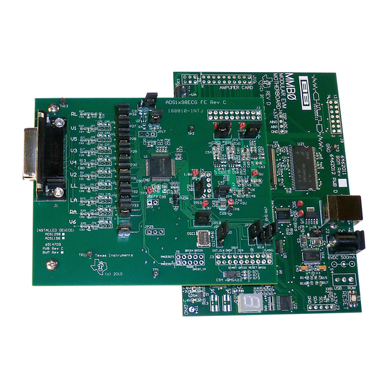
Page 35: Ads1298Ecg-Fe/Ads1198Ecg-Fe Hardware Details
Appendix The ADS1298ECG-FE can be used as a demonstration board for standard, 12-lead ECG applications with an input configuration of 10 electrodes. Users can also bypass the 12-lead configuration and provide any type of signal directly to the ADS1298 through a variety of hardware jumper settings (JP26-33; see Section A.4). -
Page 36: Jumper Description
ADS1298ECG-FE/ADS1198ECG-FE Hardware Details www.ti.com Jumper Description Table 5 shows the jumpers on the ADS1298ECG-FE and options available for each jumper. Table 5. ADS1x98ECG-FE Default Jumper/Switch Configuration Jumper Function Settings Installed RLD feedback 1-2: AVDD selected for bipolar supply operation (AVDD = +2.5V) AVDD supply source 2-3: AVDD selected for single supply operation (AVDD = +3.0V) -
Page 37: Power Supply
+2.5V –2.5V The front-end board must be properly configured in order to achieve the various power-supply schemes. The default power-supply setting for the ADS1298ECG-FE is a bipolar analog supply of ±2.5V and DVDD of either +3V or +1.8V. Table 7... -
Page 38: Clock
±5% over temperature. For applications that require higher accuracy, the ADS1298 also accepts an external clock signal. The ADS1298ECG-FE provides an option to test both internal and external clock configurations. For the external signal, circuitry is available to generate the external clock from an on- board oscillator or from an externally connected source. -
Page 39: Analog Output Signals
DRDYB Analog Input Signals The ADS1298ECG-FE provides users the option to feed in standard ECG signals from a patient simulator to the DB15 connector (J1), or to feed inputs from any arbitrary signal source directly to the ADS1298. SBAU171D – May 2010 – Revised January 2016... -
Page 40: Fluke Simulator Configuration
NOTE: Ensure that the single-ended signal has an offset equal to the voltage supplied at the negative input of the channel. ADS1298ECG-FE/ADS1198ECG-FE SBAU171D – May 2010 – Revised January 2016 Submit Documentation Feedback Copyright © 2010–2016, Texas Instruments Incorporated... - Page 41 ADS1x98ECG-FE. NOTE: Board layouts are not to scale. These are intended to show how the board is laid out; they are not intended to be used for manufacturing ADS1298ECG-FE PCBs. ADS1x98ECG-FE Front-End Board Schematics The ADS1x98ECG-FE schematic is appended to this document.
- Page 42 R66, R68, R69, R70 Not installed R3, R71, R72, R73, Resistor, 0.0Ω 1/10W 5% SMD 0603 RC0603JR-070RL Yageo Schematics, BOM, Layout, and ECG Cable Details SBAU171D – May 2010 – Revised January 2016 Submit Documentation Feedback Copyright © 2010–2016, Texas Instruments Incorporated...
-
Page 43: Appendix A Schematics, Bom, Layout, And Ecg Cable Details
Installed device is determined by Installed Device checkbox located near lower left corner of the board. SBAU171D – May 2010 – Revised January 2016 Schematics, BOM, Layout, and ECG Cable Details Submit Documentation Feedback Copyright © 2010–2016, Texas Instruments Incorporated... -
Page 44: Top Component Placement
Figure 39. Top Layer Figure 38. Top Component Placement Figure 41. Bottom Layer Figure 40. Bottom Component Placement Schematics, BOM, Layout, and ECG Cable Details SBAU171D – May 2010 – Revised January 2016 Submit Documentation Feedback Copyright © 2010–2016, Texas Instruments Incorporated... -
Page 45: Internal Ground Plane (Layer 2)
Printed Circuit Board Layout www.ti.com Figure 43. Internal Power Plane (Layer 3) Figure 42. Internal Ground Plane (Layer 2) SBAU171D – May 2010 – Revised January 2016 Schematics, BOM, Layout, and ECG Cable Details Submit Documentation Feedback Copyright © 2010–2016, Texas Instruments Incorporated... -
Page 46: Ecg Cable Schematic
• 10-lead ECG cable for Philips/HP-Clip-on type (Part No: 010303013A); http://www.biometriccables.com/index.php?productID=693 Another compatible cable for the ADS1298ECG-FE: HP/Philips/Agilent-compatible 10-lead ECG cable. Figure 44. ECG Cable Schematic Schematics, BOM, Layout, and ECG Cable Details SBAU171D – May 2010 – Revised January 2016 Submit Documentation Feedback Copyright ©... - Page 47 (refer to Section 5.7.1). Figure 45. 15-Pin, Shielded Connector from Biometric Cables SBAU171D – May 2010 – Revised January 2016 External Optional Hardware Submit Documentation Feedback Copyright © 2010–2016, Texas Instruments Incorporated...
-
Page 48: Cardiosim Ecg Simulator Tool
Figure 47. 15-Pin, Twisted Wire Cable Figure 46. 15-Pin, Twisted Wire Cable to Banana Jacks Figure 48. Cardiosim ECG Simulator Tool External Optional Hardware SBAU171D – May 2010 – Revised January 2016 Submit Documentation Feedback Copyright © 2010–2016, Texas Instruments Incorporated... -
Page 49: Recommended Power Supply For Ads1X98Ecg-Fe
ADS1x98ECG-FE with a battery source. This configuration minimizes the amount of noise pickup seen at the digitized output of the ADS1298. Figure 49. Recommended Power Supply for ADS1x98ECG-FE SBAU171D – May 2010 – Revised January 2016 External Optional Hardware Submit Documentation Feedback Copyright © 2010–2016, Texas Instruments Incorporated... - Page 50 Then follow the prompts illustrated in Figure 50 through Figure You must accept the license agreement (shown in Figure 51) before proceeding with the installation. Software Installation SBAU171D – May 2010 – Revised January 2016 Submit Documentation Feedback Copyright © 2010–2016, Texas Instruments Incorporated...
-
Page 51: Initialization Of Ads1X98Ecg-Fe
Figure 50. Initialization of ADS1x98ECG-FE Figure 51. License Agreement Figure 52. Installation Process Figure 53. Completion of ADS1x98ECG-FE Software Installation SBAU171D – May 2010 – Revised January 2016 Software Installation Submit Documentation Feedback Copyright © 2010–2016, Texas Instruments Incorporated... - Page 52 12500 TI Boulevard. Dallas, Texas 75243 Title: ADS1298 ECG FE Engineer: Tom Hendrick DOCUMENTCONTROL # REV: Drawn By: Tom Hendrick FILE: DATE: 25-Aug-2010 SIZE: SHEET: Software Installation SBAU171D – May 2010 – Revised January 2016 Submit Documentation Feedback Copyright © 2010–2016, Texas Instruments Incorporated...
- Page 53 12500 TI Boulevard. Dallas, Texas 75243 Title: ADS1298 ECG FE Engineer: Tom Hendrick DOCUMENTCONTROL # REV: Drawn By: Tom Hendrick FILE: DATE: 25-Aug-2010 SIZE: SHEET: SBAU171D – May 2010 – Revised January 2016 Software Installation Submit Documentation Feedback Copyright © 2010–2016, Texas Instruments Incorporated...
- Page 54 12500 TI Boulevard. Dallas, Texas 75243 Title: ADS1298 ECG FE Engineer: Tom Hendrick DOCUMENTCONTROL # REV: Drawn By: Tom Hendrick FILE: DATE: 25-Aug-2010 SIZE: SHEET: Software Installation SBAU171D – May 2010 – Revised January 2016 Submit Documentation Feedback Copyright © 2010–2016, Texas Instruments Incorporated...
- Page 55 12500 TI Boulevard. Dallas, Texas 75243 Title: ADS1298 ECG FE Engineer: Tom Hendrick DOCUMENTCONTROL # REV: Drawn By: Tom Hendrick FILE: DATE: 25-Aug-2010 SIZE: SHEET: SBAU171D – May 2010 – Revised January 2016 Software Installation Submit Documentation Feedback Copyright © 2010–2016, Texas Instruments Incorporated...
- Page 56 12500 TI Boulevard. Dallas, Texas 75243 Title: ADS1298 ECG FE Engineer: Tom Hendrick DOCUMENTCONTROL # REV: Drawn By: Tom Hendrick FILE: DATE: SIZE: 25-Aug-2010 SHEET: Software Installation SBAU171D – May 2010 – Revised January 2016 Submit Documentation Feedback Copyright © 2010–2016, Texas Instruments Incorporated...
- Page 57 IMPORTANT NOTICE FOR TI DESIGN INFORMATION AND RESOURCES Texas Instruments Incorporated (‘TI”) technical, application or other design advice, services or information, including, but not limited to, reference designs and materials relating to evaluation modules, (collectively, “TI Resources”) are intended to assist designers who are developing applications that incorporate TI products;...
Need help?
Do you have a question about the ADS1298ECG-FE and is the answer not in the manual?
Questions and answers