
Subscribe to Our Youtube Channel
Related Manuals for Assa Abloy ePED 1386-00


Summary of Contents for Assa Abloy ePED 1386-00
- Page 1 ePED ® Escape route technology www.assaabloy.de ePED ® door terminal 1386-00 Installation and fitting instructions The global leader in D0106404 door opening solutions...
- Page 2 ® is a registered trademark of ASSA ABLOY Sicherheitstechnik GmbH. Open Source Licenses ASSA ABLOY Sicherheitstechnik GmbH has the source code of the software used in the scope of Open Source licenses (such as FreOS™, newlib, lwIP) available on request: http://www.assaabloy.com/com/global/opensourcelicense/...
-
Page 3: Table Of Contents
Table of contents Product information ........6 ePED ®... - Page 4 Operation ..........20 Operation via key switch .
- Page 5 Set-up operation........53 Initial commissioning .
-
Page 6: Product Information
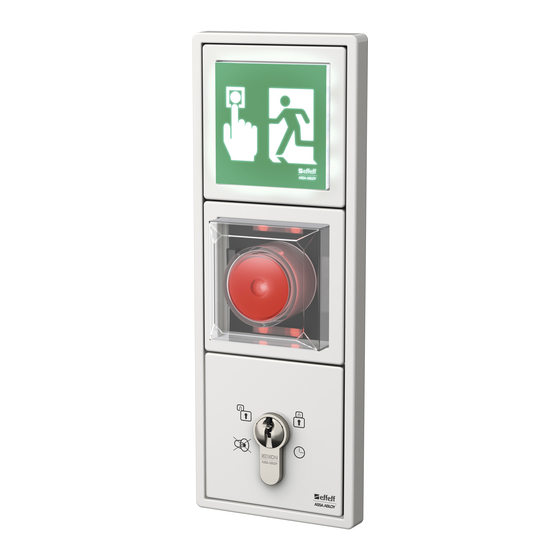
Product information ePED ® Escape Route Technology Electrical locking devices of doors along escape routes protect escape routes from misuse. The door is blocked in the escape direction in the process. In case of danger, the escape door is released with an emergency open button and an alarm is triggered. - Page 7 Fig. 1 : 1386Z00 ePED ® 1386-00 door terminal with and without down-counter module 1386-00 Down-counter module 1386D00-COUN Fig. 2 : Emergency Open push- Simplified Interface for button 1386D00 schematic diagram locking systems for connection of 1386S00 ® ePED modules Key switch module 1385ES2 Locking elements, monitor-...
-
Page 8: Notes
Notes About this manual Target groups The installation and configuration of the product must be performed by a quali- fied exp in electromechanical equipment; assembly work must be performed by a person with expise in the type of work to be performed or by appropriately trained personnel. -
Page 9: Safety Instructions
Danger due to faulty commissioning: In order to ensure the safety of the product, commissioning must be performed by a qualified person. ASSA ABLOY Sicherheitstechnik GmbH offers training for qualification in the requisite skills. Danger due to faulty maintenance: The owner is responsible for correct instal- lation and functional inspection of the product and connected components. -
Page 10: Intended Use
EltVTR. Deviating uses or device combinations not described in the approval are not permitted. ASSA ABLOY Sicherheitstechnik GmbH can provide the necessary planning informa- tion for approved solutions and the devices combinations required for your appli- cation. -
Page 11: Explanation Of Terms
Explanation of terms Term Description Activation delay With Activation delay, the key must be turned and held for longer than the ad- justed delay time for unlocking, etc. Release delay The Release delay is the wait time until the escape door is unlocked after actua- tion of the Emergency Open push-button. -
Page 12: Functions
Functions ePED ® modules Fig. 4 : ePED ® modules Emergency Open module 1386D00 The Emergency Open push-button of the Emergency Open module 1386D00 is pressed in the case of an emergency in order to request release of the locked escape door. -
Page 13: Key Switches
Key switches With the key switch, the escape door is unlocked and operation is authorised. Down-counter module 1386D00-COUN The Down-counter module 1386D00-COUN displays the remaining wait time for a delayed release of the locked escape door with green LEDs. Red LEDs also flash for as long as the escape door is locked. -
Page 14: Principle For Unlocking And Locking
Principle for unlocking and locking A locking element is locked when no release command has been issued. The locking element unlocks when one (or multiple) release commands are received. Unlocking/permanent unlocking A door is unlocked (Fig. 5) if the locking Hi-O Technology™ components receive a release command. -
Page 15: Temporary Release
Temporary release With a temporary release, the door is unlocked for passage and then locked again. For this purpose, a release command is sent to the locking Hi-O Technology™ components. After the lapse of a configured time span sufficient for passage, the release command is withdrawn. -
Page 16: Locking
Locking If all release commands have been withdrawn, a door will be locked (Fig. 7). If the escape route securing system has been activated, it monitors the times and Escape Route sequences. If the door is opened and held open, this is detected by the escape Securing System route securing system after a configured time span and an alarm is triggered (like "Temporary release,"... -
Page 17: Active And Inactive Escape Route Securing System
Active and inactive escape route securing system The escape route securing system can be activated or deactivated. Active escape route securing system If the escape route securing system is active, it basically behaves like other Hi-O Technology™ locking components. Inactive escape route securing system If the escape route securing system is inactive, the escape route locking system Door monitoring remains unlocked and the door monitoring is switched off. -
Page 18: Fire Alarm
Fire alarm In the case of a fire alarm, the Hi-O Technology™ components are actuated by a fire alarm system. The escape route locking systems are automatically unlocked and retain this status until actuation by the fire alarm system is lifted again. If the actuation by the fire alarm system is lifted again, the components lock again if no further release commands are issued. -
Page 19: Resetting To Normal Operation
Please contact the customer service of the installa- tion company or the support department of ASSA ABLOY Sicherheitstechnik GmbH ("Warranty," page 59). -
Page 20: Operation
Operation Operation via key switch ® Operation of the ePED 1386-00 door terminal via the key switch module 1385ES2 takes place with a key. The key can be turned to the left or right mechanical stop. Operation of the key switch Turn The key is turned to the mechanical stop in the indicated direction and then back to the original position (Tab. -
Page 21: Status And Operation
Status and operation LED display Alarm Operation at the key switch Status red green yellow turn to the left turn to the right Unlocked – Locking Fire alarm unlocked – Switch off Temporary release Unlock* Lock - Pre-alarm Unlock* – - Open time exceeded Unlock* –... -
Page 22: Locked - Deactivate Eped 1386-00 Door Terminal
Locked – deactivate ePED ® 1386-00 door terminal Fig. 8: The current status is: Deactivate · Locked Turn the key switch twice to the left. 9 The ePED ® 1386-00 door ter- minal has an Inactive status. 20:1 Operation... -
Page 23: Activating And Locking An Inactive Eped ® 1386-00 Door Terminal
Activating and locking an inactive ePED ® 1386-00 door terminal Fig. 9: The current status is: Activate and lock · Inactive 20:1 Turn the key switch to the right: 9 The ePED ® 1386-00 door ter- minal has an Activated and Locked status. -
Page 24: Deactivating Or Locking An Unlocked Eped 1386-00 Door Terminal
Deactivating or locking an unlocked ePED ® 1386-00 door terminal Fig. 10: The current status is: Deactivate · Unlocked Turn the key switch to the left: With activation delay acti- vated: Hold the key longer than the adjusted delay time. 9 The ePED ®... -
Page 25: Switching Off An Unlocked Fire Alarm - Acoustic Alarm
Switching off an unlocked fire alarm - acoustic alarm Fig. 12: The current status is: Switch off acoustic · Fire alarm system unlocked alarm Turn the key switch to the left: 9 The acoustic alarm is switched off. 9 The ePED ®... -
Page 26: Unlocking Or Locking A Temporarily Released Eped
Unlocking or locking a temporarily released ePED ® 1386-00 door terminal Fig. 13: The current status is: Release · Temporarily released Turn the key switch to the left: With activation delay acti- vated: Hold the key longer than the adjusted delay time. 9 The ePED ®... -
Page 27: Unlocking Eped 1386-00 Door Terminal With Temporary Release Time
Unlocking ePED ® 1386-00 door terminal with temporary release time exceeded Fig. 15: Pre-alarm Release The current status is: · Temporarily released, · the pre-alarm ("Pre-alarm and alarm," page 17) has been activated Close the escape door 9 The ePED ®... -
Page 28: Unlocking Or Temporarily Releasing A Locked Eped ® 1386-00 Door Terminal
Unlocking or temporarily releasing a locked ePED ® 1386-00 door terminal Fig. 17: The current status is: Release · Locked Turn the key switch to the left: With activation delay acti- vated: Hold the key longer than the adjusted delay time. 9 The ePED ®... -
Page 29: Release Delay
Emergency unlocking of an ePED ® 1386-00 door terminal with local release delay Fig. 19: The current status is: Emergency unlock · Local release delay Turn the key switch to the left or right: 9 The ePED ® 1386-00 door ter- minal has an Emergency re- lease status. -
Page 30: Release Delay
Emergency unlocking of an ePED ® 1386-00 door terminal with central release delay Only possible in combination with the Central control unit 1386CMC. Fig. 20: The current status is: Emergency unlock · Central release delay Turn the key switch to the left or right: 9 The ePED ®... -
Page 31: Intrusion Alarm System Is Active - (Only Status Display)
Intrusion alarm system is active – (only status display) Fig. 21: The current status is: (no operation) · Intrusion alarm system is active No operation Emergency unlock – switch off acoustic alarm (reset) Fig. 22: The current status is: Switch off acoustic ·... -
Page 32: Unlocking Or Temporarily Releasing An Eped
Unlocking or temporarily releasing an ePED ® 1386-00 door terminal blocked by Emergency Open push-button Only possible in combination with the Central control unit 1386CMC. Warning! Life-threatening danger and risk of injury from locked escape route. If the Emergency Open push-button is blocked, an alarm is triggered, but the ePED ®... - Page 33 Fig. 24: The current status is: Temporary release · Locked Turn the key switch to the right: 9 The ePED ® 1386-00 door ter- minal has a Temporary re- lease status. Operation...
-
Page 34: Fault - Switch Off Acoustic Alarm (Reset)
Fault – switch off acoustic alarm (reset) Fig. 25: The current status is: Switch off acoustic · Fault alarm · Unlocked Turn the key switch to the left: 9 The ePED ® 1386-00 door ter- minal is in normal operation 9 The acoustic alarm is switched off. -
Page 35: Tamper - Switch Off Acoustic Alarm (Reset) And Unlock
Tamper – switch off acoustic alarm (reset) and unlock Fig. 26: The current status is: Switch off acoustic · Tamper alarm alarm Turn the key switch to the left: 9 The acoustic alarm is switched off. 9 The ePED ® 1386-00 door ter- minal has an Unlocked sta- tus. -
Page 36: Operation Via The Emergency Open Push-Button
Operation via the Emergency Open push-button Resetting the Emergency Open push-button In case of an emergency, the escape door can be released with the Emergency Open module 1386D00. The release takes place immediately or after the lapse of a configured release delay. The Emergency Open push-button is locked in place after actuation. -
Page 37: Resetting To Normal Operation
Resetting to normal operation The door terminal in must be reset for normal operation after an Emergency unlock or safety-related fault. A wait time must be observed depending on the configuration (Fig. 27). Fig. 27 : Example of a configuration with a wait time 60 s Operation... - Page 38 Fitting and installation...
-
Page 39: Fitting And Installation
Identification of the cable Note! Choose uniform identification for avoidance of errors: In order to avoid errors and for a clearer overview during installation and maintenance, ASSA ABLOY Sicher- heitstechnik recommends uniform identification and colour coding of the cable cores Tab. 4. - Page 40 Fig. 28 : Dimensions of a standard flush-mounted switch box Fig. 29 : Installation in the wall Fitting and installation...
-
Page 41: Electrical Connection
Electrical connection ® The components of the ePED 1386-00 door terminal are connected to other components of the door system via the Hi-O Technology™ bus. (manual D0102100 ePED ® Hi-O Technology™ Bus). Fig. 30: Wiring Interface for locking sys- tems 1386S00 Illuminated emergency sign 1386D00-HW--F90... - Page 42 Fig. 31: Interface for locking sys- Example tems 1386S00 connection 1 Escape door strike 331 – 24 V Illuminated emergency sign 1386D00-HW SYSCON 4 SYSCON 5 Emergency Open module 1386D00 SYSCON 4 Termination via terminating resistor (Fig. 34 – Hi-O Technology™ voltage supply Other locking elements can...
- Page 43 Fig. 32: Interface for Escape door strike 331 – 24 V Example locking sys- connection 2 with tems optional down- 1386S00 counter module Illuminated SYSCON 4 emergency sign 1386D00-HW SYSCON 4 Down- SYSCON 4 counter module 1386D00-COUN SYSCON 5 Emergency Open SYSCON 4 module 1386D00 Termination via...
- Page 44 Fig. 33: Example connec- tion 3 for an escape door with distributor Distribution list Power supply Termination via terminat- ing resistor Escape door strike 331 – 24 V Interface for locking sys- tems 1386S00 Emergency Open module 1386D00 SYSCON 5 Other locking elements can be connected...
- Page 45 Note! The maximum number of components may not be exceeded: A maximum of four terminals (Emergency Open module 1386D00) and eight Interfaces for locking systems 1386S00 can be connected. The maximum power consumption may not be exceeded: The voltage supply must be sufficient for the power consumption of all connected components.
-
Page 46: Emergency Open Module 1386D00
Emergency Open module 1386D00 Fig. 34 : Front page Back page Connections of the Emergency Open button Screw-type terminal strip Attention! CAN_H CAN_L Propy damage from connection with USB devices: The jack is not a USB jack and is only intended In1 V for connecting the ePED Service In1 GND... - Page 47 In1 temporary release connection In2 fire alarm connection · No fire alarm · Local connection · Central connection + – Potential-free relay Output = Alarm message Common NC – no alarm Fitting and installation...
-
Page 48: Down-Counter Module 1386D00-Coun
Down-counter module 1386D00-COUN Fig. 35: Front page Back page Connections of Down-counter module 1386D00-COUN LED indicators: the outer green LED ring (12 LEDs) is filled on activation the inner red LED ring (4 LEDs) flashes on activation until the green LED has been filled SYSCON 4 SYSCON 4 Screw-type terminal strip... -
Page 49: Key Switch 1385Es1
Key switch 1385ES1 Attention! Damage due to electrostatic discharge: The key switch 1385ES1 must be earthed. Otherwise there is a risk of damage due to electrostatic discharge. Front page Back page Fig. 36: Key switch 1385ES1 earthing/ terminal assignment SYSCON 5 ESD cable for earthing Screw-type terminal strip Key switch, left... -
Page 50: Key Switch 1385Es2
Key switch 1385ES2 Attention! Damage due to electrostatic discharge: The key switch 1385ES2 must be earthed. Otherwise there is a risk of damage due to electrostatic discharge. Fig. 37: Front page Back page Key switch 1385ES2 earthing/ terminal assignment SYSCON 5 Screw-type terminal strip Key switch, left Key switch, right... - Page 51 Fig. 38 : Key switch 1385ES2 – single connection Jumper JP1 1 2 3 SYSCON 5 Fig. 39 : Key switch 1385ES2 – Parallel connection Jumper JP1 Jumper JP1 of two key switches 1 2 3 1 2 3 1 2 3 SYSCON 5 SYSCON 5 Fitting and installation...
-
Page 52: Connecting An Access Control System In Place Of A Key Switch
Connecting an access control system in place of a key switch Two independent inputs are available for connecting an access control system, enabling one compact device to be connected for indoors and one for outdoors, for example. The connection takes place via the SYSCON 5 connection cable for the key switch connection. -
Page 53: Set-Up Operation
Warning! Danger due to faulty commissioning: In order to ensure the safety of the product, commissioning must be performed by a qualified person. ASSA ABLOY Sicherheitstechnik GmbH offers training for qualification in the requisite skills. Safety requirements during commissioning include: ·... -
Page 54: Initial Commissioning
Initial commissioning All devices are connected to the Hi-O Technology™ for the initial commissioning, but are not configured yet. If the voltage supply is switched on, the system is in plug and play mode and the devices work with the factory settings. Interfaces for locking systems cannot work with factory settings, because they must Interface for be logically linked to the corresponding Emergency Open push-buttons. -
Page 55: Accessories
Accessories Hi-O Technology™ devices Compatibility list Note! Untested devices may have differing functionality: Hi-O Technology™ devices not listed in the compatibility list (Tab. 5) have not been tested in the device combination and may cause different functional processes. This applies especially for activators. - Page 56 Tab. 5 : Devices which have been tested in a device combination All devices compatible at the time of the printing of this manual are listed. Hi-O Technology™ Type Version Num- Rated operat- Power input device ber of ing voltage in 12 V DC 24 V DC nodes...
-
Page 57: Technical Data
Technical data Feature Characteristic Tab. 6: Technical Voltage supply V in accordance with DIN EN 60950-1 specifications SELV 12 V (–10 %) to 24 V (+10 %) Optimal voltage = 24 VDC Maximum release delay after pressing of the Emergency Open button ·... -
Page 58: Maintenance
· The safe function must be tested by a trained qualified exp at least once per year. · Requirements established by inspection authorities must be complied with, ASSA ABLOY Sicherheitstechnik GmbH offers training for qualification in the requi- site skills. Observe the following in particular: ·... -
Page 59: Warranty, Disposal
Warranty, disposal Warranty The statutory warranty periods and Terms and Conditions of Sale and Delivery of ASSA ABLOY Sicherheitstechnik GmbH apply (www.assaabloy.de). Updated information www.assaabloy.de Updated information, such as reports on current fire testing, can be found online at: www.assabloy.de Disposal Dispose of lock in accordance with the EPD (Environmental Product Declaration). -
Page 60: Appendix
Appendix Test log for commissioning Note! The test log facilitates subsequent maintenance: Fill in this test log carefully. Carefully remove and save this test log and present it to the qualified repair tech- nician in case of malfunctions. Item to be tested Test log entry Selected security settings Jumper pairs... - Page 61 Item to be tested Test log entry All mains adapters which are in use List of mains adapters which are in use: have been approved in accordance with DIN EN 60950-1 SELV. Locking elements Appendix...
- Page 64 ASSA ABLOY is the global leader in door opening solutions, dedicated to satisfying end-user needs for security, safety and convenience ASSA ABLOY Sicherheitstechnik GmbH Bildstockstraße 20 72458 Albstadt DEUTSCHLAND albstadt @ assaabloy.com Tel. + 497431 123-0 Fax + 497431 123-240...
Need help?
Do you have a question about the ePED 1386-00 and is the answer not in the manual?
Questions and answers