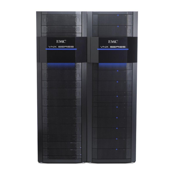
EMC VNX Series Parts Location Manual

EMC VNX Series Parts Location Manual

Hide thumbs Also See for VNX Series:

Advertisement

®
EMC
VNX
Family
VNX7500
Parts Location Guide
P/N 300-013-315
Rev 01
June 27, 2012
This guide describes one of five models available in the VNX Series, the EMC
VNX7500™. This guide is a parts location guide and provides illustrations of the part
number label locations of orderable parts for the EMC VNX7500 platform. Included in this
parts location guide are also tables describing the individual VNX7500 parts or
components and how these components are identified as either customer replaceable
units (CRUs) or field replaceable units (FRUs).
This guide is available online at
VNX Hardware Parts heading, click on the desired guide. The guide will appear in your
browser.
Topics include:
VNX7500 Block and File platform stackup ................................................................. 4
VNX7500 components .............................................................................................. 9
Standby power supplies (SPSs)................................................................................. 9
Storage processor enclosure (SPE) .......................................................................... 11
SP Power supply/cooling fan module ...................................................................... 12
SP CPU module ....................................................................................................... 13
Management module .............................................................................................. 16
Control Station........................................................................................................ 17
Data Mover enclosure ............................................................................................. 18
Data Mover Power supply/cooling fan module......................................................... 19
Data Mover CPU module.......................................................................................... 20
Management module .............................................................................................. 23
I/O modules............................................................................................................ 23
DIMMs .................................................................................................................... 39
Disk-array enclosure (DAE) ...................................................................................... 43
https://mydocs.emc.com/VNX/relatedDocs.jsp.
®
From the

Advertisement

Table of Contents
loading

Summary of Contents for EMC VNX Series

  • Page 1: Table Of Contents

    June 27, 2012 ® This guide describes one of five models available in the VNX Series, the EMC VNX7500™. This guide is a parts location guide and provides illustrations of the part number label locations of orderable parts for the EMC VNX7500 platform. Included in this...
  • Page 2: Revision History

    Product software and hardware release revisions As part of an effort to improve its product lines, EMC periodically releases revisions of its software and hardware. Therefore, some functions described in this document might not be supported by all versions of the software or hardware currently in use.
  • Page 3: How This Document Is Organized

    43 three types of DAEs available for the VNX7500. Related documentation EMC provides the ability to create step-by-step planning, installation, and maintenance instructions tailored to your environment. To create VNX customized documentation, go to: https://mydocs.emc.com/VNX/. To download a PDF copy of the desired publication, go to the following sections: For hardware-related books, go to the About VNX section, and then select Learn about ◆...
  • Page 4: Vnx7500 Block And File Platform Stackup

    Otherwise, the dual 1U SPS is used with the 2U or 3U DAE as the Vault drive. Figure 1 on page 5 shows an example of the front of a Block and File (Unified) VNX7500. The DAEs are not shown. EMC VNX7500 Parts Location Guide...
  • Page 5 On the rear, viewing from top to bottom, a Block and File (Unified) VNX7500 platform includes the following hardware components (Figure 2 on page Two 1U Control Stations ◆ Four 2U Data Mover enclosures with eight Data Movers ◆ EMC VNX7500 Parts Location Guide...
  • Page 6 Data Mover enclosure 3 (optional) Data Mover enclosure 2 (optional) Data Mover enclosure 1 (optional) Data Mover enclosure 0 Storage processor enclosure VNX-000623 Figure 2 Example of Block and File (Unified) VNX7500 platform (rear view) EMC VNX7500 Parts Location Guide...
  • Page 7: Front View

    Otherwise, the dual 1U SPS is used with the 2U or 3U DAE as the Vault drive. 2. The term Data Mover is used throughout this guide. The term Data Mover is also referred to as a blade. These terms are interchangeable and basically mean the same. EMC VNX7500 Parts Location Guide...
  • Page 8 1. Use a dual 2U SPS when a 4U DAE with Flash drives is used in a Vault drive configuration. Otherwise, the dual 1U SPS is used with the 2U or 3U DAE as the Vault drive. EMC VNX7500 Parts Location Guide...
  • Page 9: Vnx7500 Components

    The 1U SPS is primarily used in a VNX7500 platform with a 2U or 3U DAE. The 2U SPS is used in a VNX7500 platform when the 4U DAE is used as a Vault drive. EMC VNX7500 Parts Location Guide...
  • Page 10 SPS are only on the rear of the product. Figure 6 shows the part number location of the 2U SPS. SPS A SPS B Part Number (P/N) label VNX-000676 Figure 6 Example of a dual 2U SPS EMC VNX7500 Parts Location Guide...
  • Page 11: Storage Processor Enclosure (Spe)

    2.2 KW Storage processor enclosure (SPE) The 2U SPE has part numbers visible on both the front and rear. Front view Figure 7 shows the front of an 2U SPE. CNS-001723 Figure 7 SPE front view EMC VNX7500 Parts Location Guide...
  • Page 12: Sp Power Supply/Cooling Fan Module

    Note: The part number label is located on the lower half of the pull handle. Part Number (P/N) label CNS-001682 Figure 8 Example of a power supply module/cooling fan (front view) EMC VNX7500 Parts Location Guide...
  • Page 13: Sp Cpu Module

    Figure 9 Example of the SP power supply/cooling fan module removal Figure 10 on page 14 shows the SP CPU module partially removed from the front of the storage processor enclosure with the two power supply/cooling fan modules set aside. EMC VNX7500 Parts Location Guide...
  • Page 14 Figure 11 shows 2U storage processor enclosure (SPE) with two storage processors (SP A and B). VNX-000620 Figure 11 Example of the rear view of the 2U SPE chassis with two SPs (A and B) EMC VNX7500 Parts Location Guide...
  • Page 15 6. This part is not shown in the example DPE illustration in Figure 11 on page 14. For a closer view, go to Figure 29 on page Note: For illustrations and part number descriptions of the SP I/O modules, go to “I/O modules” on page EMC VNX7500 Parts Location Guide...
  • Page 16: Management Module

    Management module   303-129-100B 1. This part number is for a management module that includes a USB port. 2. This part number is for a management module that does not include a USB port. EMC VNX7500 Parts Location Guide...
  • Page 17: Control Station

    FRU or CRU. Table 8 Control Station front view part number Part number label location (Figure 13 on page Part number Description 100-520-665 Control Station (CS) 1U  EMC VNX7500 Parts Location Guide...
  • Page 18: Data Mover Enclosure

    Data Mover 2.8-GHz CPU module  without memory (for a closer view, Figure 17 on page 1. The part number label on the power supply/cooling fan module is located on the lower half of the pull handle. EMC VNX7500 Parts Location Guide...
  • Page 19: Data Mover Power Supply/Cooling Fan Module

    FRU or CRU. Table 10 Power supply module/cooling fan part number Part number label location (Figure Part number Description 071-000-543 Data Mover enclosure 400 W, 2U,   single 12 V output power supply/cooling fan module EMC VNX7500 Parts Location Guide...
  • Page 20: Data Mover Cpu Module

    Mover enclosure with the two power supply/cooling fan modules set aside. Power/cooling modules Data Mover enclosure Part Number (P/N) label Data Mover CPU CNS-001683 Figure 17 Example of the Data Mover CPU being removed from a Data Mover enclosure EMC VNX7500 Parts Location Guide...
  • Page 21 Four-port 8-Gb/s Fibre Channel (FC)   I/O Module (for a closer view, see Figure 20 on page 303-122-100A Two-port 1-Gb/s copper plus   two-port 1-G/bs optical I/O Module (for a closer view, see Figure 21 on page EMC VNX7500 Parts Location Guide...
  • Page 22 Figure 30 on page 4. This part is not shown in the example Data Mover enclosure illustration in Figure 18 on page 21. For a closer view, go to Figure 29 on page EMC VNX7500 Parts Location Guide...
  • Page 23: Management Module

    Each I/O module is identified by a part number, type of ports (copper or optical), latch handle label, and color label on top of the latch handle. For ease of identification, Table 14 on page 24 describes each I/O module type in the VNX7500. EMC VNX7500 Parts Location Guide...
  • Page 24: Data Mover

    “Two-port 10-Gb/s optical I/O module” on page 32 ◆ “Four-port 1-Gb/s copper I/O module” on page 33 ◆ “Two-port 10-Gb/s Base-T iSCSI/IP I/O module” on page 34 ◆ “Two-port 10-Gb/s optical I/O module” on page 35 ◆ EMC VNX7500 Parts Location Guide...
  • Page 25 FRU or CRU. Table 15 Four-port 8-Gb/s FC I/O Module part numbers Part number label location (Figure Part number Description 303-092-102B Four-port 8-Gb/s FC (2/4/8 Gb/s)   EMC VNX7500 Parts Location Guide...
  • Page 26 FRU or CRU. Table 16 Two-port 1-Gb/s copper plus two-port 1-Gb/s optical I/O module part number Part number label location (Figure Part number Description 303-122-100A Two-port 1-Gb/s copper plus   two-port 1-Gb/s optical EMC VNX7500 Parts Location Guide...
  • Page 27 FRU or CRU. Table 17 Two-port 10-Gb/s optical I/O module part number Part number label location (Figure Part number Description 303-081-103B or C Two-port 10-Gb/s optical I/O   module EMC VNX7500 Parts Location Guide...
  • Page 28 FRU or CRU. Table 18 Four-port 1-Gb/s iSCSI I/O module part number Part number label location (Figure Part number Description 303-141-100A Four-port 1-Gb/s iSCSI ports   EMC VNX7500 Parts Location Guide...
  • Page 29 FRU or CRU. Table 19 Two-port 10-Gb-s optical (w/iSCSI protocol) I/O module part number Part number label location (Figure Part number Description 303-081-105B Two-port 10-Gb/s optical (w/iSCSI   protocol) I/O module EMC VNX7500 Parts Location Guide...
  • Page 30 FRU or CRU. Table 20 Four-port 6-Gb/s SAS I/O Module part numbers Part number label location (Figure Part number Description 303-163-100B Four-port 6-Gb/s SAS   EMC VNX7500 Parts Location Guide...
  • Page 31 1. The FCoE I/O module can also use twinaxial (Twinax) cables. Twinax is a type of cable similar to coax, but with two inner conductors instead of one. These cables will be supplied in lieu of SFPs when so ordered. EMC VNX7500 Parts Location Guide...
  • Page 32 FRU or CRU. Table 22 Two-port optical I/O module part number Part number label location (Figure Part number Description 303-081-103B or C Two-port 10-Gb/s optical I/O   module EMC VNX7500 Parts Location Guide...
  • Page 33 FRU or CRU. Table 23 Four-port 1-Gb/s Ethernet I/O module part number Part number label location (Figure Part number Description 303-141-100A Four-port 1-Gb/s Ethernet ports   EMC VNX7500 Parts Location Guide...
  • Page 34 FRU or CRU. Table 24 Two-port 10-Gb/s Base-T iSCSI/IP I/O module part number Part number label location (Figure Part number Description 303-164-104D-01 Two-port 10-Gb/s Base-T iSCSI/IP   I/O module EMC VNX7500 Parts Location Guide...
  • Page 35 FRU or CRU. Table 25 Two-port 10-Gb/s optical I/O module part number Part number label location (Figure Part number Description 303-195-100C-01 Two-port 10-Gb/s Optical I/O   module EMC VNX7500 Parts Location Guide...
  • Page 36 Do not remove and insert an SFP or SFP+ module more often than is necessary. ◆ Repeated removals and insertions of an SFP or SFP+ module can shorten its useful life. EMC VNX7500 Parts Location Guide...
  • Page 37 2. The FCoE I/O module can also use active twinaxial (Twinax) cables. Twinax is a type of cable similar to coax, but with two inner conductors instead of one. These cables will be supplied in lieu of SFPs when so ordered. EMC VNX7500 Parts Location Guide...
  • Page 38   (SFP+) Channel (FC) I/O module Note: Only the two optical ports (physically labeled on this I/O module as 2 and 3, but logically fge- -2 and fge- -3) use this type of SFP. EMC VNX7500 Parts Location Guide...
  • Page 39: Dimms

    DIMM 4, and DIMM 5. 1. The term DIMM is used throughout this guide. The term DIMM is also referred to as a memory module. These terms are interchangeable and basically mean the same thing. EMC VNX7500 Parts Location Guide...
  • Page 40 Figure 32 Example of the Block and File VNX7500 platform SP DIMM slot location Ê100-562-264vŠ Rev : A01 ÊA01.Š P/N : 100-562-xxx Part Number (P/N) label CNS-001540 Figure 33 Example of the VNX7500 SP CPU DIMM part number location EMC VNX7500 Parts Location Guide...
  • Page 41 42). A label on the DIMM cover also identifies the DIMM slots as DIMM 0, DIMM 1, DIMM 2, DIMM 3, DIMM 4, and DIMM 5. In the VNX7500 Block and File platform, the Data Mover DIMMs are placed in slots 0, 1, 2, 3, 4, and 5. EMC VNX7500 Parts Location Guide...
  • Page 42 DIMMs Part Number (P/N) label Figure 34 Example of the VNX7500 platform Data Mover DIMM slot location EMC VNX7500 Parts Location Guide...
  • Page 43: Disk-Array Enclosure (Dae)

    Front view The DAE has three types of disk drive carriers: • 3U, 15 (3.5-inch) disk drive carrier • 2U, 25 (2.5-inch) disk drive carrier • 4U, 60 (2.5- or 3.5-inch) disk drive carrier EMC VNX7500 Parts Location Guide...
  • Page 44 Table 29 only lists some of the disk EMC VNX5500, VNX5700, and types. EMC recommends that you refer to the latest VNX7500 Series Storage Systems Disk and OE Matrix Guide to ensure that you have the correct part for your configuration.
  • Page 45 Table 30 lists only a couple disk types. EMC VNX5500, VNX5700, and VNX7500 EMC recommends that you refer to the latest Series Storage Systems Disk and OE Matrix Guide to ensure that you have the correct part for your configuration.
  • Page 46 DAE at a time. Figure 38 shows the part number label location on the front of the 4U, 60 DAE chassis. Part number (P/N) label VNX-000675 Figure 38 Example of the 4U, 60 DAE chassis (front view) EMC VNX7500 Parts Location Guide...
  • Page 47 When lifting this DAE, always use two people and a lifting device. For service personnel, when accessing this unit in a rack above 31U, always use an EMC authorized step ladder. When mounting this unit in a partially filled rack, load the rack from the bottom to the top with the heaviest component at or close to the bottom of the rack.
  • Page 48 Figure 40 4U, 60 DAE (with top cover closed) To gain access to the disk drives, LCCs, and fan control modules (after sliding the DAE out of the rack), you slide the top cover toward the rear of the DAE. EMC VNX7500 Parts Location Guide...
  • Page 49 The ICMs and power supplies shown in Figure 42 are accessed from the rear of the 4U, 60 DAE. “4U, 60 (2.5- or 3.5-inch) DAE ICM and power supply” on page 54 provides more information. EMC VNX7500 Parts Location Guide...
  • Page 50 (Figure 42 on page 49). Figure 44 shows the location of the 4U, 60 DAE disk drive part number label. Part number (P/N) label VNX-000672 Figure 44 Example of the 4U, 60 DAE disk drive EMC VNX7500 Parts Location Guide...
  • Page 51 Due to the extensive variety of disk module types, Table 32 lists only a couple disk types. EMC VNX5100 and VNX5300 Series Storage EMC recommends that you refer to the latest Systems Disk and OE Matrix Guide to ensure that you have the correct part for your configuration.
  • Page 52 FRU or CRU. Table 34 DAE 4U, 60 LCC part numbers Part number label location (Figure Part number Description (see note) 303-171-000B Link Control Card   EMC VNX7500 Parts Location Guide...
  • Page 53 LCC B power supply is located on the top of LCC B. While LCC A is located on the bottom of the DAE with LCC A on top of the LCC A power supply (Figure 47). EMC VNX7500 Parts Location Guide...
  • Page 54 4U, 60 (2.5- or 3.5-inch) DAE for the ICM and the power supply. VNX-000674 Figure 49 Example of 4U, 60 (2.5- or 3.5-inch) DAE ICM and power supply EMC VNX7500 Parts Location Guide...
  • Page 55 2. The rear of the 2U, 60 (2.5- or 3.5-inch) DAE has the DAE power supplies between ICM A and B. In other words, power supply A is located on the left of the DAE and power supply B is located on the right (Figure 49 on page 54). EMC VNX7500 Parts Location Guide...
  • Page 56 Copyright © 2012 EMC Corporation. All rights reserved. Published in the USA. Published June 27, 2012 EMC believes the information in this publication is accurate as of its publication date. The information is subject to change without notice. The information in this publication is provided as is. EMC Corporation makes no representations or warranties of any kind with respect to the information in this publication, and specifically disclaims implied warranties of merchantability or fitness for a particular purpose.

This manual is also suitable for:

Vnx7500

Table of Contents