Magnescale LY71 Instruction Manual
Counter unit
Hide thumbs
Also See for LY71:
- Simplified manual (146 pages) ,
- Instruction and installation manual (104 pages) ,
- Initial setup manual (16 pages)
Table of Contents
Advertisement
Quick Links
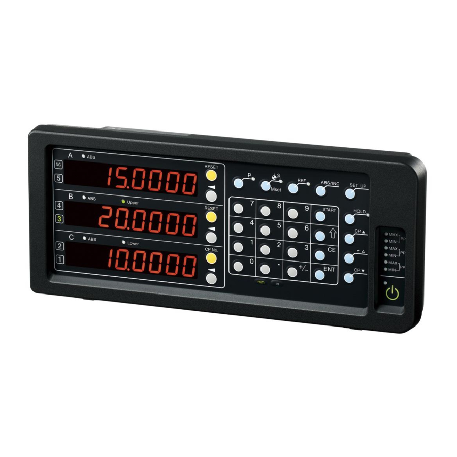
表示ユニット / Counter Unit
LY71
お買い上げいただき、ありがとうございます。
ご使用の前に、この取扱説明書を必ずお読みください。
ご使用に際しては、この取扱説明書どおりお使いください。
お読みになった後は、後日お役に立つこともございますので、必ず保管してください。
Read all the instructions in the manual carefully before use and strictly follow them.
Keep the manual for future references.
取扱説明書 (操作マニュアル) /
Instruction Manual (Operating manual)
Advertisement
Chapters
Table of Contents

Related Manuals for Magnescale LY71


Summary of Contents for Magnescale LY71
- Page 1 表示ユニット / Counter Unit LY71 お買い上げいただき、ありがとうございます。 ご使用の前に、この取扱説明書を必ずお読みください。 ご使用に際しては、この取扱説明書どおりお使いください。 お読みになった後は、後日お役に立つこともございますので、必ず保管してください。 Read all the instructions in the manual carefully before use and strictly follow them. Keep the manual for future references. 取扱説明書 (操作マニュアル) / Instruction Manual (Operating manual)
- Page 2 LY71...
-
Page 3: Table Of Contents
2-15-8. ホールド機能を外部から操作する ........2-9 2-15-9. リスタートを外部から操作する .......... 2-10 2-15-10. プリセットで入力した値を外部から設定する ....2-10 2-16. 表示を解除する ................. 2-10 2-17. 複数個のプリセットをする ..............2-10 2-18. 位置を補正する ..................2-11 2-18-1. 補正について ................2-11 2-18-2. リニア補正 ................2-11 2-19. データをBCDに出力する ............... 2-14 2-20. コンパレータを使用する ................ 2-14 LY71... - Page 4 LY71...
-
Page 5: 基本的な動作
..表示からカウント表示に切替わります。 → (カウント表 示) 測長ユニットを移動させます。 ..表示されている位置データの数値が変化します。 ∗ 数字が表示されずに 表示となる場合 ➔「2-16. 表示を解除する」へ 1-2. 表示値をゼロにする (リセット機能) 表示されている数字をゼロにします。 キーを押します。 → ∗ 外部信号でリセットさせることもできます。(参考 : 「2-15-2. 外部信号でリセットする」) ∗ カウンタ表示Cは参考表示ですので、リセットはできません。 1-3. 表示する分解能を変更する 基本設定後は、表示分解能は接続されている測長ユニットの入力分解能と同じになっています。 表示分解能を粗くする場合は、表示する分解能を変更します。 (例えば) 1秒後 カウント表示中に キーを押します。 1秒後 (例 : 0.005) キーを押します。 ..表示分解能が表示されます。 キーを押します。(ABSランプ点滅) キーを押すたびに表示が切替わります。表示したい分解能を表示させます。 キーを押します。 ..手順4で表示させた分解能が確定します。 LY71... -
Page 6: 計測したデータの最大値 / 最小値を読む
1. 基本的な動作 1-4. 計測したデータの最大値 / 最小値を読む カウンタ表示Aの キーを押します。 ..各カウンタ表示の表示データがクリアされて、全表示がゼ ロになります。 測長ユニットを+方向、–方向に移動させて計測を開始します。 計測終了後はデータが更新されます。 ..カウンタ表示B : 手順2で動いた間の最大値が表示されて います。(MAXランプ点灯) ..カウンタ表示C : 手順2で動いた間の最小値が表示されて います。(MINランプ点灯) 表示データを読んで確認してください。 1-5. 最大値 / 最小値を再計算する (リスタート機能) キーを押すと、その時点から最大値 / 最小値を計算しなおします。 キーを押します。 測長ユニットを移動させます。 ..最大値、最小値が再計算されて、表示データが更新されま す。 ∗ キーのかわりに キーを押しても再計算することができます。ただし、その場合、すべ てゼロからの再計算開始となります。(「1-4. 計測したデータの最大値 / 最小値を読む」参照) ∗ プリセット操作でも再計算となります。(「1-7. 表示に値を設定する (プリセット機能)」参照) ∗ 外部信号でリスタートさせることもできます。(「2-15-9. リスタートを外部から操作する」参 照) LY71... -
Page 7: 表示するデータを切替える (例 : 最大値→P-P値)
1. 基本的な動作 1-6. 表示するデータを切替える (例 : 最大値→P-P値) 現在表示されているデータを切替ることができます。 カウンタ表示Bの キーを押します。(ABSランプ点滅) キーを2回押します。 キーを押します。(ABSランプ消灯または点灯) ..カウンタ表示Bの表示がP-P値に替わります。 ..P-P (P-P値) = MAX (最大値) – MIN (最小値) 表示データを読んで確認してください。 ∗ 外部信号で表示データを切替えることもできます。(「2-15-3. 表示データの切替えを外部から 行なう)」参照) ∗ ここでは表示されている軸の切替えはできません。(軸の切替えは設置マニュアル「4-3. 詳細 設定をする」参照) 1-7. 表示に値を設定する (プリセット機能) 表示されている現在値に数値を設定します。 カウンタ表示Aの キーを押します。(ABSランプ点滅) キーで桁を移動し、テンキーで数値を入力します。 キーを押します。 ..入力した値が確定します。同時に、リスタート機能が働き、最大値 / 最小値も同じ値 になります。(P-P値はゼロ) ∗ プリセット操作が入力した値を外部から設定することもできます。(「2-15-10. プリセットで入 力した値を外部から設定する」参照) ∗ カウンタ表示Cは参考表示ですので、プリセットはできません。 以上が基本的な動作です。 以降はこれ以外の動作、機能についての説明となります。基本設定、詳細設定で必要な設定を行 なってから使用してください。(設置マニュアル「4. 設定」参照) LY71... - Page 8 LY71...
-
Page 9: 応用操作
2. 応用操作 注意 キーを押して軸選択状態にあるとき、別の機能キー操作を行なうと、軸選択状態は解除されま す。 2-1. 計測の基準位置を決める (基準点設定) リセット / プリセットをした位置からの計測では、ピッチ計測 (インクリメンタル (INC)) は可 能ですが、トータル寸法はわかりません。基準点を設定すると、トータル寸法も計測 (アブソ リュート (ABS)) することができます。 (「2-2. ABS表示とINC表示を切替える」参照) リセット (プリセット) リセット (プリセット) INC変化 INC変化 ピッチ寸法の計測 ピッチ寸法の計測 基準点設定 注意 • 最大値、最小値、P-P値は、INC値に対して計算されます。 • ピーク値 (最大値、最小値、P-P値) を表示しているカウンタ表示は、基準点設定はできませ ん。 キーを押します。( ランプ点灯) キーを押します。(ABSランプ点滅) キーでカウント表示の桁を送り、テンキーで基準点とする位置 (数値) を入力します。 キーで値を確定します。 ∗ 基準点を設定すると、INC値も初期化され、リセット / プリセットがされるまで、ABS値と同 じになります。 ∗ カウンタ表示Cは参考表示ですので、基準点設定はできません。 LY71... -
Page 10: Abs表示とInc表示を切替える
ランプ / ランプ点灯時はABS表示固定です。 ただし、ピーク値 (最大値、最小値、P-P値) を表示しているカウンタ表示は、INC表示固定とな り、ABS表示への切替えはできません。 (「2-1. 計測の基準位置を決める (基準点設定)」参照) キーを押します。 点灯 もとの表示に戻す場合 INC 現在値 ABS 現在値 再度 キーを押します。 2-3. 基準位置を再現する (原点操作) 原点付測長ユニットを使用している場合、あらかじめ原点操作 (下記手順) をしておけば、設定 した基準位置が不明となっても、基準位置を再現させることができます。 基準位置が不明となる場合 (例) • 電源OFF後、測長ユニットが移動した場合 • 現在値保存を保存しない設定にしている場合 (設置マニュアル「4-3. 詳細設定をする」(現在値 保存) 参照) • 使用中に電源供給がされなくなった場合 2-3-1. 基準位置の記憶 キーを押します。( ランプ点灯) キーを押します。(ABSランプ点滅) キーを押します。 測長ユニットをピッと音が鳴るまで移動させます。(原点を通過したときにピッと音がなりま す。) ..表示がホールドします。 キーを押します。 キーを押します。 ..表示のホールドが解除されます。 これにより、基準位置と原点の距離が記憶され、再現が可能になります。 LY71... -
Page 11: 基準位置の再現
キーを押します。 ..記憶されていた値が表示されます。 キーを押します。 測長ユニットをピッと音が鳴るまで移動させます。(原点を通過したときにピッと音がなりま す。) ..カウントが開始され、基準点位置が再現されます。 ∗ 基準位置の再現を、 外部信号入力で行なうこともできます。 ( 「 2-15-6. 基準位置の再現を外部信 号で行なう」 ) ∗ カウンタ表示Cは参考表示ですので、原点操作はできません。 2-4. 最大値 / 最小値の演算を中断する (ポーズ) 複数のものを連続して計測してトータルの最大値、最小値を演算させる場合、途中で計測を止め ないと必要ないデータに更新されてしまうことがあります。そのようなときに下記手順を行なう と、最大値、最小値の演算を一時的に停止することができます。 計測 例 1 qとwの間で測長ユニットが計測外の 例 2 中断する 範囲へ移動する ホールド設定で を選択します。 ➔設置マニュアル「4-3. 詳細設定をする」(ホールド機能) キーを押します。( ランプ点灯) ..最大値と最小値の演算が中断されます。 再開する場合 キーを押します。( ランプ消灯) LY71... -
Page 12: 表示データの更新を中断する (ラッチ)
2-5. 表示データの更新を中断する (ラッチ) 演算自体は中断せずに任意の位置のデータを読みとりたい場合、表示の更新のみを停止すること ができます。 ホールド設定で を選択します。 ➔ 設置マニュアル「4-3. 詳細設定をする」(ホールド機能) キーを押します。 ..表示データの更新が中断します。( ランプ点灯) 再開する場合 キーを押します。( ランプ消灯) ∗ ポーズを、外部信号入力で行なうこともできます。 2-6. 表示の縮尺を変える カウント表示の倍率を設定します。縮尺を変えた計測物を計測する場合などに有効です。 ➔ 設置マニュアル「4-3. 詳細設定をする」参照 (スケーリング) 2-7. 最小桁のちらつきをおさえる 表示値の最小桁の数字が安定せずに確認しにくい場合、表示のちらつきをおさえることができま す。 ➔ 設置マニュアル「4-3. 詳細設定をする」参照 (ちらつき防止) 2-8. キー操作の受付けを停止する (誤操作防止) 不要な操作を防ぐため、キーの受付けを停止します。 ➔ 設置マニュアル「4-3. 詳細設定をする」(キーロック) 設定後は、 (スタンバイ) キーと キー以外は受付けなくなります。 キーロックを解除する場合、パスワード入力が必要です。 キーを押すと、パスワード入力 表示になります。 ➔ 設置マニュアル「4-3-9. キーロック」 LY71... -
Page 13: 電源瞬断の検知をする / 検知を止める
2. 応用操作 2-9. 電源瞬断の検知をする / 検知を止める 出荷時の設定では、電源の瞬断があると を表示させることで、瞬断を知らせます。検知の 設定になっていると、電源投入時に が表示されます。 検知をせず、電源投入時に直接カウント表示させる設定にすることも可能です。 注意 基本設定は、カウント表示のときには行なうことができません。基本設定を変更する場合は、 表示に設定 (電源瞬断の検知をする) に戻してから行なってください。 ➔ 設置マニュアル「4-3. 詳細設定をする」(電源ON時表示) 2-10. 節電する 使用中に作業を中断するなど、しばらく操作をしないときに自動的に表示を消すことが可能で す。測長ユニットの移動やキー操作があると表示は復帰します。 ➔ 設置マニュアル「4-3. 詳細設定をする」(スリープ) 2-11. 2軸分の測長ユニットを使用して計測する 2軸分の測長ユニットのカウントを個別に表示したり、2軸分の和差を表示させたりします。これ により段差や厚みなどを計測することができます。 ➔ 設置マニュアル「4-2. 基本設定をする / 変更する」(入力軸選択) 2軸分のデータを個別に表示すれば、2軸分の最大値、最小値を計測することも可能です。 ➔ 「2-12. 軸ごとの操作」 LY71... -
Page 14: 軸ごとの操作
キーを押します。 ..カウンタ表示Aのみ切替わります。 キーを押します。 ..確定します。 参考 カウンタ表示Bの キー → キー : Bのみリスタートします。(注) カウンタ表示Aの キー → キー : Aのみホールド機能が働きます。(注) カウンタ表示Bの キー → キー : Bのみアブソリュート表示に切替わります。 (注) 同じ測長ユニットのデータを表示している軸も同時に軸が働きます。 <例> カウンタ表示A : 1軸目の最大値 カウンタ表示B : 1軸目の最小値 2-13. 表示する軸を変更する 1軸目の入力をカウンタ表示Bに表示したり、2軸目の入力をカウンタ表示Aに表示したりします。 ➔ 設置マニュアル「4-3. 詳細設定をする」(表示軸と電源ON時の表示データ) LY71... -
Page 15: マスター合わせをする
2. 応用操作 2-14. マスター合わせをする ゲージタイプの測長ユニットを使用する場合、始業時にマスター合わせという作業を行なう場合 があります。原点付きのゲージタイプの測長ユニットを使って、本表示ユニットのマスター合わ せ機能を使用すれば、マスター合わせの作業を簡略化することができます。 マスター値の設定 マスター合わせをONにします。 ➔ 設置マニュアル「4-2. 基本設定をする / 変更する」 表示の状態で キーを押します。 ..原点信号待ち状態になります。 原点を通過させます。 ..カウント表示になります。 キーを押します。 マスター合わせをするためにマスターを設置した後、ゲージタイプの測長ユニットをマス ターに当てます。 キーを押します。 テンキーでマスター値を入力します。 キーを押します。 ..マスター値が確定します。 以降は、マスター合わせ作業が不要になります。 マスター値の再現 電源を投入し、 表示の状態で キーを押します。 ..原点信号待ち状態となります。 原点を通過させます。 ..マスター値が再現されます。 以降は、マスター合わせは不要です。 ∗ マスター値の再現を、外部信号入力で行なうこともできます。(外部原点ロード入力信号を入 力します。) LY71... -
Page 16: 外部入出力
出力3、4 : カウンタ表示Bの出力信号 ∗ カウンタ表示Cは参考表示のため、出力保存の対象外です。 ➔ 設置マニュアル「4-3. 詳細設定をする」(汎用出力) 2-15-2. 外部信号でリセットする 結線が必要です。 Ex. RESET A : A軸目のリセット Ex. RESET B : B軸目のリセット。 ➔ 設置マニュアル「4-3. 詳細設定をする」(汎用入力) 2-15-3. 表示データの切替えを外部から行なう 結線が必要です。 Ex. IN A : カウンタ表示A用の入力信号 Ex. IN B : カウンタ表示B用の入力信号 Ex. IN C : カウンタ表示C用の入力信号 ➔ 設置マニュアル「4-3. 詳細設定をする」(汎用入力) 2-15-4. アラーム信号を外部に取出す 結線が必要です。 OUT A1, OUT A2 : カウンタ表示Aの出力 OUT B1, OUT B2 : カウンタ表示Bの出力 ∗ カウンタ表示Cは参考表示のため、出力保存の対象外です。 ➔ 設置マニュアル「4-3. 詳細設定をする」(汎用出力) LY71... -
Page 17: 表示モードを外部に取出す
➔ 設置マニュアル「4-3. 詳細設定をする」(汎用入力) 2-15-6. 基準位置の再現を外部信号で行なう 「2-3-2. 基準位置の再現」の操作を、外部信号で行なうことができます。 結線が必要です。 Ex. IN A : カウンタ表示A用の入力信号 Ex. IN B : カウンタ表示B用の入力信号 Ex. IN C : 使用不可 ➔ 設置マニュアル「4-3. 詳細設定をする」(汎用入力) 2-15-7. 原点通過信号を外部に取出す 原点操作時、原点を通過したときに原点通過信号を取出すことができます。原点操作をしていな いときに原点通過しても、信号は出力されません。 結線が必要です。 OUT A1, OUT A2 : カウンタ表示Aの出力 OUT B1, OUT B2 : カウンタ表示Bの出力 ∗ カウント表示Cは参考表示のため、出力保存の対象外です。 ➔ 設置マニュアル「4-3. 詳細設定をする」(汎用出力) 2-15-8. ホールド機能を外部から操作する ホールド機能 (ラッチ、ポーズ) を外部信号で行なうことができます。1度ON / OFFすると働き、 もう1度ON / OFFすると解除されます。 結線が必要です。 Ex. IN A : カウンタ表示A用の入力信号 Ex. IN B : カウンタ表示B用の入力信号 Ex. IN C : カウンタ表示C用の入力信号 ➔ 設置マニュアル「4-3. 詳細設定をする」(汎用入力) LY71... -
Page 18: リスタートを外部から操作する
2. 応用操作 2-15-9. リスタートを外部から操作する リスタートを外部信号で行なうことができます。 結線が必要です。 Ex. IN A : カウンタ表示A用の入力信号 Ex. IN B : カウンタ表示B用の入力信号 Ex. IN C : カウンタ表示C用の入力信号 ➔ 設置マニュアル「4-3. 詳細設定をする」(汎用入力) 2-15-10. プリセットで入力した値を外部から設定する プリセットで入力した値を外部から設定します。ただし、呼び出される値は、3つのうち1番目 (No. 1) の値です。 結線が必要です。 2-16. 表示を解除する 表示になった場合、 キーを押すと、表示が解除されます。ただし、エラーになる原因 が取り除かれていないと、解除はできません。 通常のリセットとの違い INC値だけでなく、ABS値もゼロになります。よって、基準点位置が変わりますので、基準点を 再現する場合は、「2-3-2. 基準位置の再現」を行なってください。マスター合わせ機能をONに設 定している場合は、マスター再現となり、原点通過が必要になります。 2-17. 複数個のプリセットをする プリセット値は3個まで保存することができます。 キーを押します。 ..数値入力可能な状態になります。 数値を入力します。 キーを押します。 ..次の数値入力に切替わります。 手順1〜3を繰返します。 2-10 LY71... -
Page 19: 位置を補正する
2. 応用操作 2-18. 位置を補正する 測長ユニットを取付けている機械等にたわみがあって位置がずれる場合、補正を入れることがで きます。以下の手順で補正値を測定してください。得られた補正量は設置マニュアルのリニア補 正で設定してください。 2-18-1. 補正について 一般的に工作機械にはあおり、たわみなど機械固有の誤差特性があります。例えばフライス盤で は、テーブルが移動するにつれて、その構造上からわずかですがニーが傾き、この傾きの水平 方向成分が測長ユニット移動量に加わり、そのまま誤差となります。そこで、移動寸法に応じ て、補正値を加算すると、機械誤差が補正されて、ワークの加工位置の実移動寸法に対し表示量 がより正確になり、寸法取りが一層高精度にできます。 出荷時の補正は、動作しない状態に設定されています。 補正値がわからない場合は、「詳細設定」でのリニア補正設定は0とし、補正量測定後に再度設 定を行なってください。 2-18-2. リニア補正 リニア補正は次の流れで設定します。 補正値 (誤差量)を測定 → リニア補正値の設定 (「詳細設定」) 補正量 : 最大 ±600 µm/m (測長ユニット入力分解能の単位で入力可能) ∗ 拡張機能にて最大 ±1000 µm/m 補正量は1 m移動したときのものです。必ず、移動量を1 mに換算した補正量の設定をしてくだ さい。 誤差 (補正量) 測定 (リニア補正) 以下に、補正量を決定するための、機械の誤差量の測定方法の一例を記載します。 ブロックケージAを機械テーブル上に置き、温度慣らしをします。 端面BにブロックゲージBを押し当てます。 (例) L = 250 mm ブロックゲージB ブロックゲージA 端面B 押し当てる 機械テーブル 2-11 LY71... - Page 20 キーを押す。 キー 電気マイクロメータ 固定側 ブロックゲージB ブロックゲージA q 測定子を当てる 機械テーブル 端面A 機械テーブルを少し移動させてブロックゲージAを取り外し、機械テーブルを再び移動さ せ、ブロックゲージBの端面Cに電気マイクロメータまたは、ダイヤルゲージの測定子を当 て、その目盛が 0 になるまで機械テーブルを移動させます。このときの表示ユニットの表 示値とブロックゲージAの長さの差がリニア補正量となるため、必ずメモします。 下記に補正量の設定例を示します。 MEMO –0.004 mm または または 0.004 mm リニア補正量をメモします。 電気マイクロメータ 固定側 ブロックゲージB w 測定子を当てる。 端面C 機械テーブル q 機械テーブルを移動させる。 e メータ 0 になるまで動かす。 移動方向 注) 測定子の高さhは、測定が終了するまで変えないでください。 2-12 LY71...
- Page 21 2. 応用操作 補正量の設定例 (リニア補正) 機械誤差の測定後、以下の方法で補正量を算出し、補正量の設定を行ないます。 移動量に対する表示量の加算、減算 L : ブロックゲージAの長さ : 端面Aから端面Cまでの距離の表示値 L > の場合は表示値に加算 最適な補正量を + で設定してください。 (例) L = 250 mm、 = 249.996 mmの場合は、 Lを1 mに換算 (L × 4) すると、 × 4 = 999.984になりますから、補正量は0.016 mmとなり ます。 L < の場合は表示値から減算 最適な補正量を – で設定してください。 (例) L = 250 mm、 = 250.004 mmの場合は、 Lを1 mに換算 (L × 4) すると、 × 4 = 1000.016 mmになりますから、補正量は–0.016 mmと なります。 2-13 LY71...
-
Page 22: データをBcdに出力する
<例> DRQ1 : 1軸目最大値 DRQ2 : 2軸目最小値 DRQ3 : 1+2軸の現在値 2枚使用の場合 1枚目 : 1軸目のデータに規制されます。 (出力可能なデータは、1軸目の現在値、最大値、最小値、P-P値) 2枚目 : 2軸目のデータに規制されます。 (出力可能なデータは、2軸目の現在値、最大値、最小値、P-P値) • 出力データの論理は、正論理、負論理どちらでも設定可能です。 • データの出力形式を3種類から選択可能です。(BCDユニット (LZ71-B) の取扱説明書参照) BCD出力の結線や動作タイミングは、BCDユニット (LZ71-B) の取扱説明書を参照してくださ い。 2-20. コンパレータを使用する 別売のコンパレータユニット (LZ71-KR) を使用すると、設定した値と大小関係を比較して、判定 結果の表示や出力信号の取出しができます。コンパレータユニットは1枚のみ使用可能です。 比較対象 1軸目のデータ (現在値、最大値、最小値、P-P値)、または1軸目と2軸目の加算データ 比較対象のデータの選択 詳細設定で行ないます。 判定結果はラッチ入力で保持することも可能です。 判定結果を信号で取出す 判定の結果は、リレー信号とオープンコレクタ信号で出力可能です。 リレー信号もオープンコレクタ信号も判定結果一箇所のみONします。 詳しくは、コンパレータユニット (LZ71-KR) の取扱説明書を参照してください。 2-14 LY71... - Page 23 2-17. Clearing the Display ..............2-10 2-18. Presetting Multiple Points ................2-10 2-19. Compensating the Position ................. 2-11 2-19-1. Compensation ................2-11 2-19-2. Linear Compensation ..............2-11 2-20. Outputting Data to BCD ................2-14 2-21. Using the Comparator ................2-14 LY71...
- Page 24 LY71...
-
Page 25: Basic Operation
..The display resolution is shown. Press the key. (The ABS lamp flashes.) The display changes each time the key is pressed. Press until the desired display resolution is shown. Press the key..The resolution displayed in step 4 is set. LY71... -
Page 26: Reading The Maximum/Minimum Values Of Measured Data
(See “1-4. Reading the Maximum/Minimum Values of Measured Data”.) ∗ Recalculation is also possible using the preset operation. (See “1-7. Setting Values to the Display (Preset Function).”) ∗ Restart is also possible with an external signal. (See “2-16-9. Operating restart from an external device”.) LY71... -
Page 27: Switching The Display Data (Example: Maximum Value → Peak-To-Peak Value)
∗ Counter display C is a reference display, and so it cannot be preset. This completes the basic operations. The next sections describe other operations and functions. Be sure to make the necessary settings in the basic and advanced settings before using. (See “4. Settings” in the Installation Manual.) LY71... - Page 28 LY71...
-
Page 29: Applied Operation
∗ When the datum point is set, the INC value is initialized and is identical to the ABS value until it is reset or preset. ∗ Counter display C is a reference display, and so it cannot set the datum point. LY71... -
Page 30: Switching Between The Abs Display And Inc Display
Move the measuring unit until it beeps. (The beeping sound is made when going past the reference point.) ..The display is held. Press the key. Press the key..The hold on the display is canceled. This enables storing and relocation of the distance between the datum point position and reference point. LY71... -
Page 31: Relocation Of The Datum Point Position
Select in the Hold setting. ➔ Installation manual “4-3. Advanced Settings” (Hold function) Press the key. (The lamp lights on.) ..The calculation of the maximum and minimum values is paused. Restarting Press the key. (The lamp lights off.) LY71... -
Page 32: Pausing Updates Of Display Data (Latch)
After making the setting, the only valid key operations are the (Standby) key and key. A password must be entered to remove the key lock. Pressing the key displays the password input display. ➔ Installation manual “4-3-9. Key Lock” LY71... -
Page 33: Power Outage Detection On/Off
➔ Installation manual “4-2. Making and Changing Basic Settings” (Input Axis Selection) If the data for two axes are displayed individually, the maximum value and minimum value of the two axes can also be measured. ➔ “2-13. Operation for each Axis” LY71... -
Page 34: Operation For Each Axis
2-14. Changing the Display Axis This can display the 1st axis input on counter display B and the 2nd axis input on counter display A. ➔ Installation manual “4-3. Advanced Settings” (Display axis, and display data at power ON) LY71... -
Page 35: Master Calibration
..The master calibration value is relocated. After this is completed, the master calibration operation is no longer necessary. ∗ Relocation of the master calibration value can also be performed by input from an external signal. (An external reference point load input signal is input.) LY71... -
Page 36: External Input/Output
OUT A1, OUT A2 : Counter display A output OUT B1, OUT B2 : Counter display B output ∗ Counter display C is a reference display, and so output saving is not possible. ➔ Installation manual “4-3. Advanced Settings” (General-purpose output) LY71... -
Page 37: Sending The Display Mode To An External Device
ON/OFF once, and it is disabled when turned ON/OFF again. Connections are required. Ex. IN A: Input signal for counter display A Ex. IN B: Input signal for counter display B Ex. IN C: Input signal for counter display C ➔ Installation manual “4-3. Advanced Settings” (General-purpose input) LY71... -
Page 38: Operating Restart From An External Device
Up to three preset values can be saved. Press the key..A numerical value can be entered. Enter a numerical value. Press the key..This switches to entry of the next numerical value. Repeat steps 1 to 3. 2-10 LY71... -
Page 39: Compensating The Position
Then touch the surface B of the block gauge A with a block gauge B. Example: L = 250 mm (L = 9.84250 in) Block gauge B Block gauge A Surface B Contact block gauges A and B Machine table 2-11 LY71... - Page 40 Block gauge B w Touch probe to surface Surface C Machine table q Move the machine table. e Move it until the meter reads “0.” Movement direction Note: Do not change the probe height h until finished measuring. 2-12 LY71...
- Page 41 , subtract a compensation amount from the displayed value. Set an appropriate negative compensation amount. Example : If L = 250 mm and = 250.004 mm If L is converted to 1m (L × 4), × 4 = 1000.016, so the compensation amount is –0.016 mm. 2-13 LY71...
-
Page 42: Outputting Data To Bcd
The judgment results can be output by relay signals and open collector signals. Only one judgment result location is turned on for the relay signals and open collector signals. For details, see the Comparator Unit (LZ71-KR) Instruction Manual. 2-14 LY71... - Page 43 Co., Ltd. et sont destinées exclusivement à l'usage des acquéreurs de l'équipement décrit dans ce manuel. Magnescale Co., Ltd. interdit formellement la copie de quelque partie que ce soit de ce manuel ou son emploi pour tout autre but que des opérations ou entretiens de l'équipement à...
- Page 44 〒 108-6018 東京都港区港南2丁目 15番1号 品川インターシティA棟18階 Shinagawa Intercity Tower A-18F, 2-15-1, Konan, Minato-ku, Tokyo 108-6018, Japan LY71 2010.4 3-288-167-02 Printed in Japan ©2007 Magnescale Co., Ltd. このマニュアルは再生紙を使用しています。...
Need help?
Do you have a question about the LY71 and is the answer not in the manual?
Questions and answers