Magnescale LH70 Operation Manual
Tool offset function
Hide thumbs
Also See for LH70:
- Initial setup manual (13 pages) ,
- Quick reference manual (6 pages) ,
- Quick start manual (3 pages)
Advertisement
Quick Links
LH70
Tool offset function
Operation manual
START
Table of contents
1. First of all
2. Target model
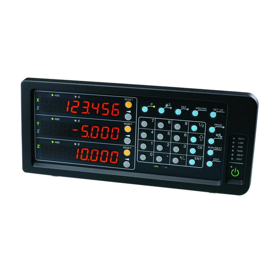
3. Front panel
4. Positional relationship between TOOL master (reference) and other TOOLs (conceptual diagram)
5. Settings
and operations
1. First of all
The tool offset function is used in absolute mode (ABS). You must set up a tool master to use this function. The
coordinate position of each tool is a coordinate value managed by the offset amount with respect to the tool master.
Therefore, if you change the value of the tool master, the coordinates of other tools will change automatically.
The tool master is set to number 1 in the factory settings, but in this operation manual, the tool master is set to a tool
number that is not normally used. Then, in the actual operation, we will explain how to set and operate only the tools
that are normally used without using the tool master.
NOTE: Set the X-axis display setting to diameter display (Φ lamp lights up).
OPERATION FLOW
STEP 1
Change tool
master number
coordinate settings
Contents
Change tool master number
STEP 1
Tool master coordinate setting (for scale with reference point)
STEP 2-1
Tool master coordinate setting (for scale with reference point)
STEP 2-2
Setting the number and offset value of the tool to be used
STEP 3
LH70 Tool offset function Operating manual
STEP 2
Tool master
Setting the number
and offset value
Ver. 3 (2021.1)
LH70
Finished
STEP 3
Page
1
2
2
2
3
3
4
5
CS&S
1/5
Advertisement

Related Manuals for Magnescale LH70


Summary of Contents for Magnescale LH70
- Page 1 Then, in the actual operation, we will explain how to set and operate only the tools that are normally used without using the tool master. NOTE: Set the X-axis display setting to diameter display (Φ lamp lights up). LH70 Tool offset function Operating manual...
- Page 2 P0 = (X0, Z0) Datum point P1 = (X0+X1, Z0+Z1) * The tool master is set to No. 1 at the P2 = (X0+X2, Z0+Z2) time of shipment from the factory. TOOL 1 TOOL 2 LH70 Tool offset function Operating manual...
- Page 3 Since a general lathe uses about 8 tools at a time, change the tool master to 12. Turn on the power of the display unit, you do not have to attach the tool. Tool offset for LH70-3 : up to 12 points Press the tool offset key to enter tool offset mode.
- Page 4 Set the tool number to #1. Operate the key, numeric key, and key on the lower display to enter "1". TOOL1 (Lower) Fig.1 (Continued on the next page) LH70 Tool offset function Operating manual...
- Page 5 If the tip of the cutting tool is worn, the machining dimensions are misaligned, or the sharpness is getting worse, replace the cutting edge of the cutting tool or polish the cutting edge, and then perform steps 1 to 5 in step 3 to reset the value. LH70 Tool offset function Operating manual...
Need help?
Do you have a question about the LH70 and is the answer not in the manual?
Questions and answers