Magnescale LY71 Initial Setup Manual
Hide thumbs
Also See for LY71:
- Simplified manual (146 pages) ,
- Instruction and installation manual (104 pages) ,
- Instruction manual (44 pages)
Advertisement
Quick Links
LY71
Initial Setup Manual
Advance
START
Preparation
Check the conditions of use
Table of contents
Preparations before making the initial settings (checking conditions of use)
How to set up Advanced Settings (continued from Basic Settings)
How to set up the BCD unit (optional)
How to set up a comparator unit (optional)
Factory Default (All Clear)
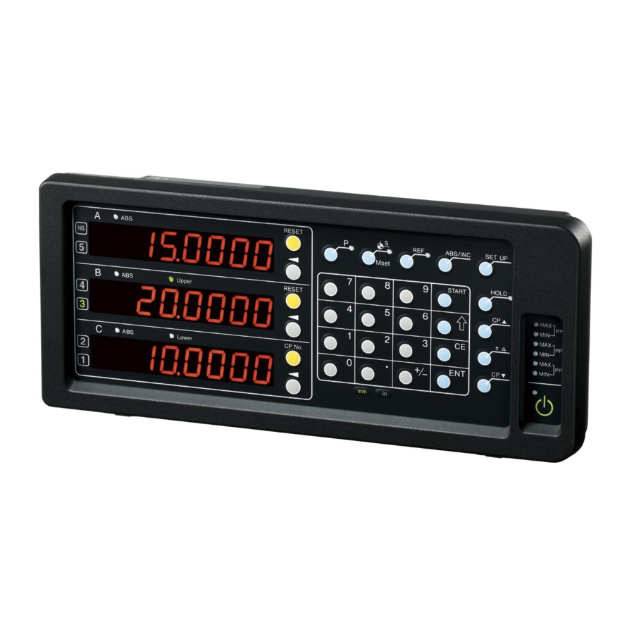
Appendix 1: Front panel, Alarm Indication
Appendix 2: Adapter connections (scales and gauges)
Initial Setup Flow
Basic
Contents
LY71 Initial Setup Manual
LZ71-B
Advanced
Option
Settings
Note: Not required if the option is not used
STEP 6~7
STEP 6~7
Ver.2 (2020.11) CS&S
Confirmation: software version 1.15
LY71
LZ71-KR
(Note)
Finished
Page
2 to 4
5 to 7
8 to 10
11
12
13
14
15 to 16
1/16
Advertisement

Related Manuals for Magnescale LY71


Summary of Contents for Magnescale LY71
-
Page 1: Table Of Contents
How to set up the BCD unit (optional) STEP 6~7 How to set up a comparator unit (optional) STEP 6~7 Factory Default (All Clear) Appendix 1: Front panel, Alarm Indication Appendix 2: Adapter connections (scales and gauges) 15 to 16 1/16 LY71 Initial Setup Manual... - Page 2 SZ70-1 SR128 / SR127 0.5μm CH01-LW**C SZ51-MS01 + SZ70-1 DL310B/330B 10μm DZ-51 SZ70-1 SR138R(GB-ER) 0.5μm CH04-03C DK series 0.1μm or CE29-** 0.5μm * For adapter information, refer to Appendix 2 Adapter Connection in this Manual 2/16 LY71 Initial Setup Manual...
- Page 3 10:10 minutes later moved or the Key operation is performed again. 30:30 minutes later 60: 60 minutes later Note 3: When a comparator unit(LZ71-KR) is connected, the first and second axes cannot be displayed independently. 3/16 LY71 Initial Setup Manual...
- Page 4 Data selection C: Current value * Be sure to set the data request signal. A: Maximum value The initial value is set to the second axis I: Minimum value P: P-P value Data Axis selection selection 4/16 LY71 Initial Setup Manual...
- Page 5 Note: When the comparator unit is connected, the first and second axes cannot be displayed independently. ◆ A/B-phase output unit (LZ71-HT01) The minimum phase difference (Tw) of the output signal is the same as the connected scale unit signal. Example) GB-ER: Tw=200ns Standard for DK812SA: Tw=50ns DK812SB: Tw=100ns 5/16 LY71 Initial Setup Manual...
-
Page 6: How To Set Up Basic Settings
(Independent display, the scale to be connected. dimensions every time the axis-added display, etc.) Supports the input of length power is turned on. and angle display units. COUNTRY (Destination) Symbol Destination Unit General area U.S.A. Japan 6/16 LY71 Initial Setup Manual... - Page 7 - The current setting is displayed after about one second. If there is no change in the setting, the next item is displayed with key. 1μm - The ABS lamp blinks while the parameter is selected with the axis selection key.. 7/16 LY71 Initial Setup Manual...
-
Page 8: Step 1~3
After the second time, the screen is displayed when the power is turned on. ⑤ Press key. The display returns to normal. This completes the basic settings. Key to be used at the end of the basic setting mode (LY71) Reset key ABS lamp Select axis key Setup key... - Page 9 Enter a correction value of ±0.600mm per 1m of distance Liner Error Input up to ±1.0000 mm with expansion selection. (Linear compensation) default Enter numerical values on a numeric keypad. ~ Normal ~ Extended selection 9/16 LY71 Initial Setup Manual...
- Page 10 10 min. 6. When the advanced settings are complete, switch to the normal display. Step 5 Press key. This completes the initial settings.. If the option I/O (BCD unit, comparator unit) is connected, continue setting. 10/16 LY71 Initial Setup Manual...
- Page 11 BCD2 to the second axis. axis P-P value Step 7 When the setting is complete, switch to the normal display. Press key. This completes the initialization process. 11/16 LY71 Initial Setup Manual...
- Page 12 Setting in Manual Note: When setting two or more comparator values, select "Manual". Automatic Step 7 6. When the setting is complete, switch to the normal display. Press key. This completes the initialization process. 12/16 LY71 Initial Setup Manual...
- Page 13 4. Turn off the primary power supply to the AC adapter. How to check the software version: Power ON → Display LY → Key → Version Press any key to return to the LY display. 13/16 LY71 Initial Setup Manual...
-
Page 14: Step 6~7
Measurement unit not Storage data error connected Reference point detection Speed over (Note) error Overflow (Light) Power failure Note: When using an adapter connection (SZ**), no speed override indication is shown, but rather an error message. 14/16 LY71 Initial Setup Manual... - Page 15 Scale Resolution Adapter Counter SR-1711(GP)、SR10A/741(GS)、 0.5μm SZ05-T01 LG20 SR50A(GF,GF-R)、SR30A(GM)、 LH70/71/71A/72 SR801/801R(GL) LY71/72 Screws * HA13A, 15A, 23A and 25A are used as head amps SZ05-T01 Head-amp Connector Screws Use screws to secure it in place. 15/16 LY71 Initial Setup Manual...
- Page 16 Head-amp Connector Screws Use screws to secure it in place. Gauge Resolution Adapter Counter DE12BR/30BR 0.1μm SZ70-1 LG20 LH70/71/71A/72 Counter unit LY71/72 Cable (300mm) Screws Head-amp Use screws to secure it in place. Connector SZ70-1 16/16 LY71 Initial Setup Manual...
Need help?
Do you have a question about the LY71 and is the answer not in the manual?
Questions and answers