Mitel Aastra 470 System Manual
R3.2
Hide thumbs
Also See for Aastra 470:
- System functions and features (502 pages) ,
- System manual (272 pages) ,
- System manual (302 pages)
Table of Contents
Advertisement
Quick Links
Aastra Business Communication
Solution
Aastra 470 as of R3.2
System Manual
Platforms supported:
Aastra 470
This document contains information on the expansion
stages, system capacity, installation, configuration, run-
ning and maintenance of this Aastra communication
systems as well as their technical data.
It is intended for planners, installers and system manag-
ers of Aastra 400 communication systems.
syd-0337_en / 1.6 – R3.2 – © 09.2014
Advertisement
Table of Contents

Subscribe to Our Youtube Channel
Related Manuals for Mitel Aastra 470


Summary of Contents for Mitel Aastra 470
- Page 1 Aastra Business Communication Solution Aastra 470 as of R3.2 System Manual Platforms supported: Aastra 470 This document contains information on the expansion stages, system capacity, installation, configuration, run- ning and maintenance of this Aastra communication systems as well as their technical data.
-
Page 2: Table Of Contents
Expansion with cards and modules.......46 Aastra 470 as of R3.2... - Page 3 Fitting DSP modules ......... . . 107 Aastra 470 as of R3.2...
- Page 4 User accounts ..........184 Aastra 470 as of R3.2...
- Page 5 Preparations ........... 207 Aastra 470 as of R3.2...
- Page 6 Operating state and error displays......250 Aastra 470 as of R3.2...
- Page 7 Index ........... 283 Aastra 470 as of R3.2...
-
Page 8: Product And Safety Information
The expansion possibilities for the Aastra 470 communication server include an ap- plications server for unified communications and multimedia services, an FMC Controller for integrating mobile phones, an open interface for application devel- opers and a multitude of expansion cards and modules. - Page 9 • the Aastra 400 products conform to the basic requirements and other relevant stipulations of Directive 1999/5/EC. • all our products are manufactured in conformity with RoHS (2011/65/EU). The product-specific declarations of conformity can be found on the Aastra 400 DocFinder. Aastra 470 as of R3.2 syd-0337/1.6 – R3.2 – 09.2014...
- Page 10 Aastra 400 products are disassembled exclusively using detachable screwed con- nections. Not valid for Australia. For Australia, see "Limited Warranty (Australia only)", page 278. Aastra 470 as of R3.2 syd-0337/1.6 – R3.2 – 09.2014...
-
Page 11: Safety Information
Interruptions in the power supply will cause the entire system to restart. A UPS system has to be connected up-circuit to ensure an uninterruptible power supply. Up to a specific performance limit a Aastra 470 communication server can also be operated redundantly using an auxiliary power supply. For more information please refer to your communication server's system manual. -
Page 12: Data Protection
• For WAN links used for transmitting calls from IP or SIP phones, use as a matter of preference either the customer's own dedicated leased lines or with VPN en- crypted connection paths. Aastra 470 as of R3.2 syd-0337/1.6 – R3.2 – 09.2014... -
Page 13: About This System Manual
• Document version: 1.6 • Valid as of: R3.2 • © 09.2014 Aastra Technologies Limited • In PDF viewer, click on this link to download the latest version of this document: https://pbxweb.aastra.com/doc_finder/DocFinder/syd-0337_en.pdf?get&DNR=syd-0337 Aastra 470 as of R3.2 syd-0337/1.6 – R3.2 – 09.2014... - Page 14 Failure to observe information identified in this way can cause a defect to a module. Warning Failure to observe information identified in this way can lead to damage caused by electrostatic discharge. Aastra 470 as of R3.2 syd-0337/1.6 – R3.2 – 09.2014...
-
Page 15: About Aastra
With a strong focus on open standards, Aastra enables enterprises to communicate and collaborate more efficiently. For additional information on Aastra, visit our website. Aastra 470 as of R3.2 syd-0337/1.6 – R3.2 – 09.2014... -
Page 16: System Overview
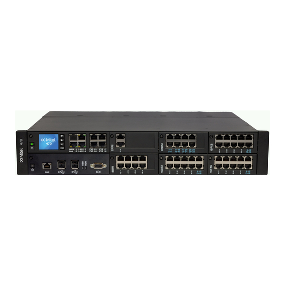
2. 2 Communication server Aastra 470 is the most powerful communication server in the Aastra 400 family. It is designed for installation in a 19” rack, but can also be set up on a flat surface. With the exception of the power supply and earthing, all the connections and con- trol elements are accessible from the front. -
Page 17: Positioning
Applications range from small businesses or branches to large companies at one or more locations. Up to 36 users can be operated on the Aastra 470 communication server without licensing. And with an expansion licence up to 400 users are possi- ble. -
Page 18: Networking Possibilities
The range of services avail- able in a virtual network depends on the range of services offered by the network provider. The DSS1 ISDN protocol is the main protocol used. Aastra 470 as of R3.2 syd-0337/1.6 – R3.2 – 09.2014... -
Page 19: Aastra System Phones And Clients
The digital system phones of the Office family (Office 10, Office 25, Office 35, Office 45 and Office 45pro) are supported as before (not all system features can be used). Aastra 470 as of R3.2 syd-0337/1.6 – R3.2 – 09.2014... - Page 20 • Can be used as operator console • Wall mounting possible when combined with expansion • Web configuration interface key module Note: The Aastra 5360ip IP system phone is supported as before. Aastra 470 as of R3.2 syd-0337/1.6 – R3.2 – 09.2014...
- Page 21 • Journal with call lists, text messages and notes • Workgroups (agent control) • Possibility of synchronisation with a Microsoft Exchange server • Possibility of displaying various additional windows • All the system features can be used Aastra 470 as of R3.2 syd-0337/1.6 – R3.2 – 09.2014...
- Page 22 DECT® only). Note: The Aastra 610d, Aastra 620d, Aastra 630d, Office 135/135pro and Office 160pro/Safeguard/ATEX cordless sys- tem phones are supported as before (not all system features can be used). Aastra 470 as of R3.2 syd-0337/1.6 – R3.2 – 09.2014...
- Page 23 • Wall mounting possible General: • Power over Ethernet • Additional model-specific fea- tures include the resolution, the display type and size, and the number of configurable or fixed function keys. Aastra 470 as of R3.2 syd-0337/1.6 – R3.2 – 09.2014...
- Page 24 • Wall mounting possible • Additional model-specific fea- • Power over Ethernet (except tures include the resolution, the Aastra 6730i) display type and size, and the number of configurable or fixed function keys. Aastra 470 as of R3.2 syd-0337/1.6 – R3.2 – 09.2014...
- Page 25 • Ideally suited for hospitality and hotel environments Note: The Aastra 1910 and Aastra 1930 analogue phones are still supported. Aastra 470 as of R3.2 syd-0337/1.6 – R3.2 – 09.2014...
-
Page 26: Various Phones, Terminals And Equipment
With the Aastra Mobile Client application all the main telephony functions are available with menu prompting (see "Aastra Applications", page 28). Aastra 470 as of R3.2 syd-0337/1.6 – R3.2 – 09.2014... -
Page 27: Solutions
(see "Application interfaces", page 30). Auxiliary applications for planning and the configuration and park management are available as a web application. Aastra 470 as of R3.2 syd-0337/1.6 – R3.2 – 09.2014... -
Page 28: Aastra Applications
• Team functions such as presence key and abbreviated dialling • Directory integration • Pre-installed on the applications card CPU2 of the Aastra 470 communi- cation server • Aastra 400 CCS is an additional application for the Aastra 400 Call Center, and provides statistics / reporting functions and agent monitoring (CCS = call centre supervision). - Page 29 Fax messages can also directly be sent from MS applications via a special printer driver. • Pre-installed on the applications card of the Aastra 470 communication server The application card CPU2 is no longer available.
-
Page 30: Application Interfaces
IP softphones provider applications Open Interfaces Platform (OIP) OIP Connectors Automation and alarm Communication system External directories systems Fig. 3 OIP as middleware between communications system, external data sources and applications Aastra 470 as of R3.2 syd-0337/1.6 – R3.2 – 09.2014... - Page 31 Connection of external data sources OIP supports the connection of external directories and it is also possible to set up adaptable alarming and messaging systems. Aastra 470 as of R3.2 syd-0337/1.6 – R3.2 – 09.2014...
-
Page 32: Message And Alarm Systems
An alarm is triggered if the phone remains in a virtually horizontal position or motionless for some time or if the handset is shaken violently. Aastra 470 as of R3.2 syd-0337/1.6 – R3.2 – 09.2014... -
Page 33: Cti - Computer Telephony Integration
For this purpose the First-Party TAPI Service Provider (AIF-TSP) is required. Application example • Dialling from a database (phone book CD, etc.) • Caller identification (CLIP) • Creating a call journal Aastra 470 as of R3.2 syd-0337/1.6 – R3.2 – 09.2014... -
Page 34: Isdn Interface
The system status is monitored with event messages which can be sent to various internal or external destinations like printer, server, e-mail recipient, etc. Event mes- sages are also accessible via the Open Interfaces Platform for application manufac- turers. Aastra 470 as of R3.2 syd-0337/1.6 – R3.2 – 09.2014... -
Page 35: Call Logging
System Search. The getting-started package is available for downloading via the following hyperlinks: Tab. 13 Getting started Communication server Aastra 415/430 Aastra 470 Download getting-started package syd-0418h syd-0419h Aastra 470 as of R3.2 syd-0337/1.6 – R3.2 – 09.2014... -
Page 36: Connection Options
Fixed Mobile Convergence Controller Monitor Aastra Mobile Client Plus Ethernet Applications server Keyboard, mouse, etc. Ethernet Message and alarm systems Hotel Management Systems Fig. 4 Overview of interfaces with possible terminal equipment Aastra 470 as of R3.2 syd-0337/1.6 – R3.2 – 09.2014... -
Page 37: Expansion Stages And System Capacity
3. 1 Summary Expansion possibilities for the Aastra 470 basic systems at a glance. The interface cards are fitted from the front into one of a total of 7 slots. System modules are fit- ted either to the call manager card or to interface cards. System modules are also used on other platforms: The DSP modules with Aastra 415/430 and the IP media modules with Aastra 5000. -
Page 38: Basic System
Expansion Stages and System Capacity The basic system Aastra 470 can be expanded not just with interface cards and sys- tem modules but also with an applications card (CPU2). The applications card is supplied with preinstalled operating system, unified communications and multi- media applications. - Page 39 Redundant fan unit as an option (RFU) Backplane (BP2U) Call Manager card (CPU1) Plug-in connections for the interface cards Fig. 7 Aastra 470 basic system fitted with a redundant fan unit Aastra 470 as of R3.2 syd-0337/1.6 – R3.2 – 09.2014...
-
Page 40: Interfaces, Display And Control Elements
Earth connection Mains socket for 115/230 V power supply input 115/230 V voltage converter Socket for auxiliary power supply unit APS2 1 fewer slot if CPU2 application card is fitted Aastra 470 as of R3.2 syd-0337/1.6 – R3.2 – 09.2014... - Page 41 The figure below shows the positions of the interfaces and of the display and con- trol elements on the call manager card. [10] Fig. 9 Interfaces, display and control elements of the call manager card CPU1 Aastra 470 as of R3.2 syd-0337/1.6 – R3.2 – 09.2014...
-
Page 42: Power Supply
Power supply Internal power supply unit PSU2U The Aastra 470 communication server is powered as standard directly with a mains cable. The voltage converter needs to be set to the correct position to match the mains power (230 VAC or 115VAC) (see also "Powering the communication server",... - Page 43 Mains power 115/230 VAC Fig. 10 Overview of the Aastra 470 power supply concept Notes – It is also possible to operate the communication server with the exter- nal power supply unit APS2 only In this case redundancy operation is of course no longer possible.
-
Page 44: Ethernet Concept
3. 2. 3 Ethernet concept Aastra 470 provides three GBit Ethernet interfaces, which are routed to the front panel of the call manager card. They are used to connect to the customer’s data network (LAN) and e.g. the IP connection with an SIP provider. The socket marked "WAN"... -
Page 45: Dsp Resources
Can be used without licence subject to the following restrictions: Voice memory capacity approx. 20 min- utes, no e-mail notification in the event of new voice messages, no forwarding of voice messages, no call re- cording, restricted voice mail menu by remote retrieval. Aastra 470 as of R3.2 syd-0337/1.6 – R3.2 – 09.2014... -
Page 46: Expansion With Cards And Modules
3. 3 Expansion with cards and modules An Aastra 470 basic system can be individually expanded using interface cards, sys- tem modules and an application card. The number and position of the available slots are described in the chapter "Interfaces, display and control elements",... - Page 47 Connections between IP and non-IP endpoints are made via an IP media gate- way. This is carry out by the integrated standard media switch that switches VoIP channels for call connections in the IP network. The Standard Media Switch uses Aastra 470 as of R3.2 syd-0337/1.6 – R3.2 – 09.2014...
- Page 48 "Configuration of DSP chips", page 52). Note With the Aastra 470 communications server G.711 voice channels are always used for voice mail, auto attendant and call recording. The parameter SVM mode can therefore not be changed for this system. Aastra 470 as of R3.2...
- Page 49 Sufficient transmitters / receivers are already available for 1 PRI interface on the DSP of the Call Manager card (see Tab. 16). If this is not sufficient, additional senders/receivers can be configured with this setting. Aastra 470 as of R3.2 syd-0337/1.6 – R3.2 – 09.2014...
- Page 50 • Music on hold In normal operation all IP endpoints are registered with • Conversation recording the master, even if they are located on the satellite. • Queue with announcement Aastra 470 as of R3.2 syd-0337/1.6 – R3.2 – 09.2014...
- Page 51 Maximum available audio channels on this node. This value depends on the DSP configuration. Reserved for voice mail Number of audio channels on this node that can be used exclusively for voice mail. Aastra 470 as of R3.2 syd-0337/1.6 – R3.2 – 09.2014...
- Page 52 G.711/G.729: 5 channels Only for VoIP mode G.711 G.711/G.729 Only for VoIP mode G.711 G.711/G.729 Licence(s) required (see also "Licences", page 67). Of relevance only to certain countries such as Brazil Aastra 470 as of R3.2 syd-0337/1.6 – R3.2 – 09.2014...
- Page 53 – The system has to be restarted for the configuration changes of the DSP to take effect. – After a first start all the DSP chips are configured on DECT. Although no longer available, the module is still supported. Aastra 470 as of R3.2 syd-0337/1.6 – R3.2 – 09.2014...
-
Page 54: Ip Media Module
Tab. 24 Max. number of voice channels per IP media module G.711 only, G.711/G.729, Type FoIP (T.38) Secure G.711 Secure G.711/G.729 EIP1-8 EIP1-32 Aastra 470 as of R3.2 syd-0337/1.6 – R3.2 – 09.2014... -
Page 55: Call Charge Modules
4FXO trunk card 8FXO trunk card 16FXO trunk card 4TAX – – 8TAX – – 16TAX – – The availability of the call charge modules depends on the sales channel. Aastra 470 as of R3.2 syd-0337/1.6 – R3.2 – 09.2014... -
Page 56: Interface Cards
The splits can also be made elsewhere, e.g. using system cables available separately (see "Prefabricated system cable 4 x RJ45", page 112). Fig. 15 Example of an interface card (2PRI with 2 IP media modules fitted) Aastra 470 as of R3.2 syd-0337/1.6 – R3.2 – 09.2014... -
Page 57: Trunk Cards
• 1 call charge module can be fitted for 16 ports 1 fewer card if CPU2 application card is fitted The availability of the FXO trunk cards depends on the sales channel. Aastra 470 as of R3.2 syd-0337/1.6 – R3.2 – 09.2014... -
Page 58: Terminal Cards
• All interfaces configurable to BRI-T 4 BRI-S 8BRI • Four fixed BRI-T interfaces • 4 BRI-S interfaces configurable to BRI-T 1 fewer card if CPU2 application card is fitted Aastra 470 as of R3.2 syd-0337/1.6 – R3.2 – 09.2014... -
Page 59: Cpu2-S/Cpu2 Applications Card
The meaning of the status LEDs is explained in the chapter "Application server dis- play and control panel", page 230. The maximum permissible current input at the USB interfaces varies: The application card CPU2 is no longer available. Aastra 470 as of R3.2 syd-0337/1.6 – R3.2 – 09.2014... - Page 60 Installing user-specific applications is prohibited. See also: For more information about installing, configuring and upgrading the software of the application card, see the CPU2-S application card installa- tion manual. Aastra 470 as of R3.2 syd-0337/1.6 – R3.2 – 09.2014...
-
Page 61: System Capacity
Note: The values in the following three tables relate to a communication server with an Aastra 470 Expansion expansion licence. Without this licence the system is limited to the first 36 users in the numbering plan, which means many values in the table are not valid. - Page 62 First-party CTI users via Aastra Dialer Third-party CTI interfaces Third-Party CTI Interface (Basic, Standard) Groups, Agents (Call centre) Mailboxes with Basic or Enterprise voice mail system Greetings per mailbox Profiles per mailbox for auto attendant Aastra 470 as of R3.2 syd-0337/1.6 – R3.2 – 09.2014...
- Page 63 Depending on the highest number of line keys, configured for the same line. The following pairs apply (line keys per line / total line keys): (16/48), (14/56), (12/72), (10/100), (8/160), (6/240), (4/320), (2/400). Aastra 470 as of R3.2 syd-0337/1.6 – R3.2 – 09.2014...
-
Page 64: Terminals
Operator consoles / operator appli- Aastra 5380 cations Aastra 1560 Office 45 Cordless System SB-4+ radio unit Cordless System SB-8 / SB-8ANT radio units DSI-DASL Digital system phones Dialog 4220 Dialog 4222 Dialog 4223 Aastra 470 as of R3.2 syd-0337/1.6 – R3.2 – 09.2014... - Page 65 Terminals on DSI-S interfaces (total) Terminals as per ETSI standard • ISDN terminals • ISDN PC cards • ISDN LAN routers • ISDN Terminal Adapters Terminals on FXS interfaces (total) Aastra 470 as of R3.2 syd-0337/1.6 – R3.2 – 09.2014...
-
Page 66: Terminal And Network Interfaces
Primary rate interfaces PRI SIP access SIP access channels 30 B channels per PRI network interface, of which 10 B channels each can be used without licence. Licences required Aastra 470 as of R3.2 syd-0337/1.6 – R3.2 – 09.2014... -
Page 67: Licences
Without a valid Software Release licence you can update the communication server to a new The licence (as well as the temporary/definite activation tool) is not available in each sales channel. Aastra 470 as of R3.2 syd-0337/1.6 – R3.2 – 09.2014... - Page 68 • Aastra Video Terminals To use the video functions of an Aastra BluStar 8000i Desktop Media Phone or Aastra BluStar for Conference Room, in addition to the Aastra SIP Terminals Aastra 470 as of R3.2 syd-0337/1.6 – R3.2 – 09.2014...
- Page 69 The licences are needed to register the clients on the system. BluStar • BluStar Softphones for Aastra 400 This is a BluStar client licence. One licence per client is required to operate Aastra 470 as of R3.2 syd-0337/1.6 – R3.2 – 09.2014...
- Page 70 This licence enables the use of the auto attendant function and is independent of the Enterprise Voice Mail licence. It means it can also be used in conjunction with basic voice mail. One licence is required per system /AIN. Aastra 470 as of R3.2 syd-0337/1.6 – R3.2 – 09.2014...
- Page 71 Note: The Master can also be an Aastra 470. Resources • Aastra 470 Expansion This licence cancels out the restriction to the first 36 users in the numbering plan of the Aastra 470 communication server. The maximum system capacities can be found in Tab. Tab. 32 Tab.
- Page 72 Expansion Stages and System Capacity Aastra Intelligent Net In an AIN with an Aastra 470 as Master and more than 36 users, an Aastra 470 Expansion licence is required only for the Master. The Aastra 470 satellites do not need a licence, even if they have more than 36 users (except of course for offline operations lasting more than 36 hours).
- Page 73 These licences are used to implement a private leased-line network with QSIG by enabling a specific number of simultaneously outgoing QSIG channels. Two li- cence levels are available (see Tab. 34). Aastra 470 as of R3.2 syd-0337/1.6 – R3.2 – 09.2014...
- Page 74 Applications • Licences for the fax service on the CPU2 The CPU2 applications card of an Aastra 470 communication server contains software with a server-based fax solution. Use of this fax service is licensed as fol- lows: –...
- Page 75 Interfaces • ATAS Interface / ATASpro Interface With ATAS licences external alarm and messaging sources can be connected via the Ethernet interface. The licences also offer additional possibilities compared Aastra 470 as of R3.2 syd-0337/1.6 – R3.2 – 09.2014...
- Page 76 • Dialling by name is deactivated. • Functions cannot be invoked via the menu or function key (likewise no enquiry calls can be made). • The team keys do not work. Aastra 470 as of R3.2 syd-0337/1.6 – R3.2 – 09.2014...
- Page 77 This procedure can only be used once for each function or feature. Thereafter you must acquire a licence. The licence overview (Tab. shows which trial licences are available. Aastra 470 as of R3.2 syd-0337/1.6 – R3.2 – 09.2014...
- Page 78 Aastra SIP Aastra SIP Terminals. 1, only on the terminal 20 or 50 additional Master; Aastra SIP terminals otherwise with video functional- per node. ity per licence. Aastra 470 as of R3.2 syd-0337/1.6 – R3.2 – 09.2014...
- Page 79 BluStar soft- BluStar softphone. 1, only on the Aastra 400 phone 20 or 50 additional Master; BluStar softphones otherwise with video functional- per node. ity per licence. Aastra 470 as of R3.2 syd-0337/1.6 – R3.2 – 09.2014...
- Page 80 Master; otherwise per node. ✓ ✓ Analogue Modem Use of the modem func- unavaila- enabled In the AIN, tionality on an Aastra only on the 415/430. Master; otherwise per node. Aastra 470 as of R3.2 syd-0337/1.6 – R3.2 – 09.2014...
- Page 81 Master Aastra Intelligent Additional satellite in an Additional licence for Only on – – Net Satellites Basic Aastra Intelligent the Master Net. 1 additional satel- lite per licence Aastra 470 as of R3.2 syd-0337/1.6 – R3.2 – 09.2014...
- Page 82 In the AIN, Basic Package site for all other only on the OpenCount licences. Master; Enables connection to otherwise the Aastra 400 and the per node. use of basic functions. Aastra 470 as of R3.2 syd-0337/1.6 – R3.2 – 09.2014...
- Page 83 "General system Master; capacity", page otherwise per node. TWP Connection Connection to Teleph- unavaila- enabled Licence is – – ony Web Portal (TWP) enabled when user- based TWP licences are availa- Aastra 470 as of R3.2 syd-0337/1.6 – R3.2 – 09.2014...
- Page 84 Back-licensing is not provided for. However, resetting to the factory set- ting is possible. OIP licences OIP licences are managed by OIP itself. A detailed description of the OIP licences can be found in the System Manual Open Interfaces Platform. Aastra 470 as of R3.2 syd-0337/1.6 – R3.2 – 09.2014...
-
Page 85: Power Supply Capacity
DSP modules, the IP media modules, the CPU2 applications card and the redundant fan unit (P Tab. 36 Power requirements of Aastra 470 hardware components Designation Output P [W] Basic system with CPU1 call manager card... - Page 86 – Line length: 200 m The table below shows the average power requirements of the terminals for a line length of approx. 200 m and a wire diameter of 0.5 mm. Aastra 470 as of R3.2 syd-0337/1.6 – R3.2 – 09.2014...
- Page 87 The value applies to phones with hardware version "-2". The value for phones with hardware version "-1" is 60 mW lower. The value depends greatly on the terminal type. With the planning application Aastra Plan the power supply available for terminals is checked automatically. Aastra 470 as of R3.2 syd-0337/1.6 – R3.2 – 09.2014...
-
Page 88: Power Supply Per Interface
DSI interface cards. Tab. 38 Maximal power supply per interface card Maximal power supply per interface card Output P [W] DSI interface card 41.5 Aastra 470 as of R3.2 syd-0337/1.6 – R3.2 – 09.2014... -
Page 89: Power Supply Per Terminal Interface
• Terminals used incl. auxiliary devices • Bus configuration • Line length and conductor cross-section For information on the calculations refer to "Terminal interfaces", page 129. Aastra 470 as of R3.2 syd-0337/1.6 – R3.2 – 09.2014... -
Page 90: Installation
Installation Installation This Chapter tells you how Aastra 470 can be installed and the conditions to be observed. It also includes the mounting into a 19” rack, the correct way to connect the earthing, and the power supply. Other topics in this chapter in- clude how to fit system modules and interface cards. -
Page 91: Fitting The Communication Server
Installation 4. 2 Fitting the communication server The Aastra 470 communication server is designed for installation in a 19” rack (2 height units). The communication server can also simply be placed on a flat sur- face. Wall-mounting is not allowed. -
Page 92: Safety Regulations
Always touch the earthed metal case of the communication server before carrying out work inside the housing. This also applies to interface cards and system modules that are no longer packed inside the ESD protective wrapping. Aastra 470 as of R3.2 syd-0337/1.6 – R3.2 – 09.2014... -
Page 93: Flow Of Hot Air
4. 2. 4 Flow of hot air The Aastra 470 communications server comes with a fan already pre-installed. The housing is designed so the air flow is first guided at two levels over the processor cards and the interface cards, then passes through cutouts in the backplane, ab- sorbs the heat from the power supply unit, and exits the housing through the fan aperture. -
Page 94: Desktop Installation
4. 2. 6 Rack-mounting The rack mounting of the Aastra 470 communication server allows it to be installed horizontally in a 19” rack. Be sure to observe the following: • The communication server takes up the space of 2 height units (units) inside the 19”... -
Page 95: Fitting An Additional Fan
Fans have a limited service life. So if a fan fails become of age ( approx. 5 years) it is advisable to replace both fans as a precautionary measure. Materials required: • Aastra 470 additional fan premounted on fastening frame • Set of screws for additional fan • Screwdriver To install the additional fan proceed as follows: 1. - Page 96 Redundant fan unit Fastening frame Fig. 19 Fitting the additional fan in Aastra 470 Notes for proper fitting of the backplane BP2U If the upper rear housing cover is open (e.g. to install an additional fan) the backplane may jump out of the bottom guide slots (especially, if there are no cards fitted yet).
- Page 97 Backplane (BP2U) Must be flush 4 bottom guide slots 3 fastening brackets with contact springs 4 top guide slots Upper rear housing cover Fig. 20 Proper fitting of the backplane BP2U Aastra 470 as of R3.2 syd-0337/1.6 – R3.2 – 09.2014...
-
Page 98: Earthing And Protecting The Communication Server
Operation on an IT current distribution system: The communication server can be operated on an IT power distribution system as per EN/IEC 60950 with voltages of up to 230 VAC. Aastra 470 as of R3.2 syd-0337/1.6 – R3.2 – 09.2014... -
Page 99: Connecting The Earthing Wire
2,5 mm protected 4,0 mm protected 4,0 mm Building earth unprotected Building earth unprotected Fig. 22 Earthing of the communication server in the case of direct cabling and indirect cabling Aastra 470 as of R3.2 syd-0337/1.6 – R3.2 – 09.2014... -
Page 100: Connecting The Cable Screening
APS2 can be used to increase the power supply available or to increase operating reliability (redundancy in the event of a failure on the part of one of the two power supplies). The communication server can also be operated with the ex- Aastra 470 as of R3.2 syd-0337/1.6 – R3.2 – 09.2014... -
Page 101: Internal Power Supply Unit
Fig. 24). Warning PCBs may be damaged or become defective if the communication server is operated on 230 V mains power and the voltage converter is set to 115 V. Aastra 470 as of R3.2 syd-0337/1.6 – R3.2 – 09.2014... -
Page 102: External Auxiliary Power Supply Unit
In redundancy operation, connect the communication server power sup- ply and the APS2 auxiliary power supply unit to separately protected mains power. This will further enhance the system's operating reliability. Aastra 470 as of R3.2 syd-0337/1.6 – R3.2 – 09.2014... - Page 103 The following diagram shows the fan-out-panel FOP from below with the auxiliary power supply fitted. Connection panel FOP Fastening board Auxiliary power suply unit (APS2) Fastening board Fig. 25 Fan-out-panel with auxiliary power supply fitted (viewed from below) Aastra 470 as of R3.2 syd-0337/1.6 – R3.2 – 09.2014...
-
Page 104: Uninterruptible Power Supply (Ups)
The uninterrupted operation of the communication server is ensured if the UPS takes over the power supply within 20ms of the mains outage. See also For more technical details see "Technical data", page 261. Aastra 470 as of R3.2 syd-0337/1.6 – R3.2 – 09.2014... -
Page 105: Equipping The Basic System
Installation 4. 5 Equipping the Basic System For individual expansion the Aastra 470 basic system can be fitted with interface cards, system modules and an application card. An overview can be found in the Chapter "Expansion Stages and System Capacity", page 4. -
Page 106: Fitting Application Card Cpu2
7. Start up the applications server by pressing the On/Off button on the applica- tions card. See also: For more information about installing, configuring and upgrading the software of the application card, see the CPU2-S application card installa- tion manual. Aastra 470 as of R3.2 syd-0337/1.6 – R3.2 – 09.2014... -
Page 107: Equipping The Call Manager Card Cpu1
IP media module Spacer sleeve DSP modules Fastening screw Spacer sleeve Fastening screw of the call manager card Call manager card Fig. 27 System modules on the Call Manager card Aastra 470 as of R3.2 syd-0337/1.6 – R3.2 – 09.2014... -
Page 108: Fitting Ip Media Modules
3. Remove the 2 fastening screws on the 2 premounted spacer sleeves on the IP Media module. 4. Place the module in the slot and press it down evenly into the slot as far as the stop. Aastra 470 as of R3.2 syd-0337/1.6 – R3.2 – 09.2014... -
Page 109: Fitting Call Charge Modules
1. Shut down the call manager via the control panel (see "On/Off key", page 225). 2. Unscrew the screw on the FXO card and remove the card by pulling the fasten- ing screw. Aastra 470 as of R3.2 syd-0337/1.6 – R3.2 – 09.2014... -
Page 110: Component Mounting Rules
– The interfaces are enabled in accordance with their designation, starting with the lower designations. This means that the terminal interfaces on the proces- sor card are always enabled before those on the interface cards. Aastra 470 as of R3.2 syd-0337/1.6 – R3.2 – 09.2014... -
Page 111: Connecting The Communication Server
There are two possibilities for connecting the communication server indirectly to the telephone network and terminal-side cabling: • Connection via main distribution board • Connection to a universal building cable installation (UBC) Aastra 470 as of R3.2 syd-0337/1.6 – R3.2 – 09.2014... -
Page 112: Connection Via Main Distribution Board
With terminal cards with 16 or more interfaces some or all of the RJ45 sockets are assigned four-fold on the front panel of the Aastra 470. With this cable they can be connected without the use of a fan-out-panel (FOP). The cable is 6 m long and at one extremity has four RJ45 connectors on which all the pins are wired. - Page 113 "Connection of PRI primary rate interface", page 121 "Connec- tion of Ethernet interfaces", page 160). Use standard commercial connecting cables not just for the PRI and Ethernet interfaces but also for connecting the BRI-T interfaces. Aastra 470 as of R3.2 syd-0337/1.6 – R3.2 – 09.2014...
- Page 114 – turquoise – violet – – blue – turquoise – violet – – orange – turquoise – violet – View A View B Fig. 31 Pin numbering, RJ45 connector Aastra 470 as of R3.2 syd-0337/1.6 – R3.2 – 09.2014...
-
Page 115: Connection To A Universal Building Cable Installation (Ubc)
Connecting to a UBC via a (main) distribution board (example) Communica- tion server User Patch panel Phone User side Phone Exchange side Public exchange Fig. 33 Connecting to a UBC via wiring centre (example) Aastra 470 as of R3.2 syd-0337/1.6 – R3.2 – 09.2014... -
Page 116: Cabling Interfaces
A port address is always of the type x.y. x is the number of the card slot, and y, the port number. The slot numbering starts with 1 and ends with 8 (see "Number of the Aastra 470 slots", page 105). -
Page 117: Network Interfaces
Equipping the system with interface cards provides the necessary network inter- faces. With the exception of the Ethernet interface, which also represents a network interface via SIP access, there are no network interfaces on the Aastra 470 commu- nication server. - Page 118 Basic access in the private leased-line network BRI-T BRI-S Copper line extern PINX 1 PINX 2 max. 1,000 m Fig. 37 BRI-S basic rate interface , networked with copper line external Aastra 470 as of R3.2 syd-0337/1.6 – R3.2 – 09.2014...
- Page 119 PINX 2 signal, basic rate inter- Cable cores Network Cable cores basic rate inter- face BRI-T face BRI-T See also Chapter "Connections with basic accesses" in the PISN/QSIG Networking System Manual. Aastra 470 as of R3.2 syd-0337/1.6 – R3.2 – 09.2014...
-
Page 120: Primary Rate Interface Pri
90 to 130 (1 MHz) Characteristic impedance Wave attenuation < 6 dB/km (100 kHz), < 26 dB/km (1 MHz) Near/crosstalk attenuation > 54 dB/100 m (1 kHz to 1 MHz) Aastra 470 as of R3.2 syd-0337/1.6 – R3.2 – 09.2014... - Page 121 Primary rate access in the private leased-line network 4-wire Copper line PINX 1 PINX 2 max. 200 m 4-wire Copper line PINX 1 PINX 2 max. 200 m Fig. 41 Primary rate access, networked with copper line Aastra 470 as of R3.2 syd-0337/1.6 – R3.2 – 09.2014...
- Page 122 — — — — — — — — Transmission facilities PINX 1 PINX 2 max. max. 200 m 200 m Fig. 42 Primary rate interface, networked with transmission equipment Aastra 470 as of R3.2 syd-0337/1.6 – R3.2 – 09.2014...
- Page 123 — — — — — — Leased-line or dial-up PINX 1 PINX 2 connection Mains power Mains power Fig. 43 Primary rate access PRI, networked with leased-line or dial-up connection Aastra 470 as of R3.2 syd-0337/1.6 – R3.2 – 09.2014...
- Page 124 PRI signal PRI PINX 2 RJ45 straight patch Straight patch signal work signal cable cable — — — — — — — — See also: System Manual “PISN / QSIG Networking” Aastra 470 as of R3.2 syd-0337/1.6 – R3.2 – 09.2014...
-
Page 125: Fxo Network Interfaces
– Inadmissibly high temperatures can occur on the FXO card when con- necting to local exchanges generating a very high loop current (up to 90mA). If so, the PCB temperature monitoring deactivates the FXO Aastra 470 as of R3.2 syd-0337/1.6 – R3.2 – 09.2014... - Page 126 Connection Assignment of the RJ45 sockets on the front panel: Tab. 54 Connection FXO network interface Communication server Public analogue network FXO signal Socket – – – – – – Aastra 470 as of R3.2 syd-0337/1.6 – R3.2 – 09.2014...
- Page 127 FXO signal FXO signal Socket necting cables – – – – – – – – – – – – – – – – – – – – – – – – Aastra 470 as of R3.2 syd-0337/1.6 – R3.2 – 09.2014...
- Page 128 Cable requirements for FXO network interface Core pairs cores 1 2 Stranded not required Wire diameter, core 0.4 … 0.8 mm Screening not required max. 2 250 Resistance Aastra 470 as of R3.2 syd-0337/1.6 – R3.2 – 09.2014...
-
Page 129: Terminal Interfaces
Connection of individually assigned DSI terminal interface Communication server Cable cores Connection socket Socket DSI signal DSI signal Socket – – – – – – – – – – – – Aastra 470 as of R3.2 syd-0337/1.6 – R3.2 – 09.2014... - Page 130 Socket DSI signal DSI signal Socket – – – – – – – – – – – – – – – – – – – – – – – – Aastra 470 as of R3.2 syd-0337/1.6 – R3.2 – 09.2014...
- Page 131 DSI-DASL interface. The maximum line length for a 0.5 mm wire diameter is set at 1000 m. Office 10, Office 25, Office 35, Office 45/45pro are supported as before Aastra 470 as of R3.2 syd-0337/1.6 – R3.2 – 09.2014...
- Page 132 Although no longer available, the phone is still supported. The value can increase to approx. 600 mW if the power available at the DSI-AD2 bus allows it. An Aastra M535 always requires a power supply unit Aastra 470 as of R3.2 syd-0337/1.6 – R3.2 – 09.2014...
- Page 133 2000 1900 1800 1700 1600 1500 1400 d=0.4mm 1300 1200 R [Ohm] d=0.5mm 1100 d=0.6mm 1000 Line length L [m] Fig. 47 Power available A on the DSI-AD2 bus Aastra 470 as of R3.2 syd-0337/1.6 – R3.2 – 09.2014...
- Page 134 – An Aastra 5380 with 3 Aastra M530 expansion key modules always requires a power supply unit. With 2 expansion key modules the use of power supply unit depends on the line length and the line cross-sec- tion. Aastra 470 as of R3.2 syd-0337/1.6 – R3.2 – 09.2014...
- Page 135 Power requirements as per Tab. 60: 1340 + 300 + 300 = 1940 mW. Fig. 47 indicates: • Maximum line length for a wire diameter of 0,4 mm: 520 m Aastra 470 as of R3.2 syd-0337/1.6 – R3.2 – 09.2014...
- Page 136 • Avoid using different cable cross-sections on the same bus • Use the supplied cables for connecting the system phones • Cabling of AD2 terminals is restricted to pairs of a separate dedicated cable(s). Applies in Australia only Aastra 470 as of R3.2 syd-0337/1.6 – R3.2 – 09.2014...
-
Page 137: Bri-S Terminal Interfaces
With the 8BRI card, only the interfaces of sockets 1 to 4 are available for BRI-S terminal interfaces. The interfaces of sockets 5 to 8 are permanently configured to BRI-T. Office 10, Office 25, Office 35, Office 45/45pro are supported as before Aastra 470 as of R3.2 syd-0337/1.6 – R3.2 – 09.2014... - Page 138 The maximum number of terminals per S bus depends on the power requirements of the terminals (see "Restrictions", page 139). 8. Connection point Communica- 2 x 100 Ω tion server max. 150 m Fig. 50 S bus, short Aastra 470 as of R3.2 syd-0337/1.6 – R3.2 – 09.2014...
- Page 139 These values are based on a wire diameter of 0.5 mm. The number of terminals is the sum of the power requirements of the individual terminals and the power available on the S bus. Aastra 470 as of R3.2 syd-0337/1.6 – R3.2 – 09.2014...
- Page 140 Fit resistors at bus extremity only Fig. 55 RJ45 connection, double socket Installation rules Always terminate the bus extremity with 2 100 (0.25 W, 5%)! Note Circuit type as per EN/IEC 60950: SELV Aastra 470 as of R3.2 syd-0337/1.6 – R3.2 – 09.2014...
- Page 141 • ISDN Terminal Adapter • PC with ISDN card • Group 4 fax machines , etc. Two call connections are possible simultaneously for each S bus. Not possible within an AIN Aastra 470 as of R3.2 syd-0337/1.6 – R3.2 – 09.2014...
-
Page 142: Fxs Terminal Interfaces
EFOP emergency fan-out panel. In the event of a power failure the EFOP switches the connected analogue phones automati- cally and directly over to the analogue FXO exchange lines (see "Emer- gency fan-out-panel (EFOP)", page 154). Aastra 470 as of R3.2 syd-0337/1.6 – R3.2 – 09.2014... - Page 143 Connection of individually assigned FXS terminal interface Communication server Cable cores Connection socket Analogue Analogue Socket Socket signal signal – – – – – – – – – – – – Aastra 470 as of R3.2 syd-0337/1.6 – R3.2 – 09.2014...
- Page 144 Analogue Analogue Socket Socket signal signal – – – – – – – – – – – – – – – – – – – – – – – – Aastra 470 as of R3.2 syd-0337/1.6 – R3.2 – 09.2014...
- Page 145 • Radio units for cordless phones • Group 3 fax • Answering machines • Modem Transmission with the T.38 protocol is recommended for Fax over IP. The corresponding DSP resources need to be allocated. Aastra 470 as of R3.2 syd-0337/1.6 – R3.2 – 09.2014...
- Page 146 In this mode 2-wire door intercoms with DTMF control functions can be connected. The no-load voltage in this mode is 24 VDC. The loop current is limited to 25 mA. FXS interface Fig. 58 Connection for FXS mode: 2-wire door Aastra 470 as of R3.2 syd-0337/1.6 – R3.2 – 09.2014...
- Page 147 DC or AC voltage imposed. Make sure that the mode of the FXS interface is configured to External audio source before connecting audio equipment. Aastra 470 as of R3.2 syd-0337/1.6 – R3.2 – 09.2014...
- Page 148 There are no special requirements for the cables. Warning Control outputs must have a floating connection. max. 25mA 24 VDC FXS interface Fig. 60 Connection for FXS mode: Control output Aastra 470 as of R3.2 syd-0337/1.6 – R3.2 – 09.2014...
- Page 149 • The same switch group can only be switched by the 2 assigned control inputs. • Control of the switch groups using the control inputs takes priority over control using function codes. Aastra 470 as of R3.2 syd-0337/1.6 – R3.2 – 09.2014...
-
Page 150: Fan-Out Panel Fop
The fan-out panel (FOP) takes up the space of one height unit in a rack and can be fitted directly above or below the communication server. Fig. 63 Front panel, FOP fan-out-panel Fan-out panels can also be offset, e.g. as floor distributors. Aastra 470 as of R3.2 syd-0337/1.6 – R3.2 – 09.2014... - Page 151 260). The internal wiring of the fan-out panel is shown in the table below. The wiring is shown for sockets 1 - 4. Sockets 5 - 8 are wired accordingly. Aastra 470 as of R3.2 syd-0337/1.6 – R3.2 – 09.2014...
- Page 152 Fan-out panel FOP Socket Signal Signal Socket – – – – – – – – – – – – – – – – – – – – – – – – Aastra 470 as of R3.2 syd-0337/1.6 – R3.2 – 09.2014...
- Page 153 Fig. 65). Aastra 470 Copper wire yellow/green 2,5 mm protected 4,0 mm unprotected Stranded copper yellow/green 4,0 mm unprotected Fig. 65 Connection of the FOP fan-out-panel to the protective earth Aastra 470 as of R3.2 syd-0337/1.6 – R3.2 – 09.2014...
-
Page 154: Emergency Fan-Out-Panel (Efop)
The fan-out panel EFOP takes up the space of one height unit in a rack and can be fitted directly above or below the communication server. Available as of R2.1 SP1 Aastra 470 as of R3.2 syd-0337/1.6 – R3.2 – 09.2014... - Page 155 Auxiliary power suply 1 … 8 1 … 8 unit (APS2) Communication server relevant only with APS2 auxiliary power supply unit in redundancy operation Fig. 67 Block diagram, EFOP fan-out-panel Aastra 470 as of R3.2 syd-0337/1.6 – R3.2 – 09.2014...
- Page 156 FXS line and the exchange line prior to the emer- gency operation. – In emergency operation the emergency phone is connected directly with the analogue exchange line so no exchange access prefix has to be dialled. Aastra 470 as of R3.2 syd-0337/1.6 – R3.2 – 09.2014...
- Page 157 The patch cables are available separately in lengths of 1 and 2 m (see "Equipment Overview", page 260). The internal wiring of the 3 right-hand connection blocks is the same as for the FOP fan-out-panel (see Tab. 73). Aastra 470 as of R3.2 syd-0337/1.6 – R3.2 – 09.2014...
- Page 158 • Original power supply units FSP065 (19 VDC / 3.42 A) are to be used exclusively. • The EFOP fan-out-panel is designed for installation in a 19” rack and must be fit- ted in rack only. Aastra 470 as of R3.2 syd-0337/1.6 – R3.2 – 09.2014...
- Page 159 EFOP fan-out-panel only. – In redundancy operation, connect the communication server and the APS2 auxiliary power supply unit to separately protected mains power. This will further enhance the system's operating reliability. Aastra 470 as of R3.2 syd-0337/1.6 – R3.2 – 09.2014...
-
Page 160: Ethernet Interfaces
4. 7. 6 Ethernet interfaces The communication server Aastra 470 has a Gbit Ethernet switch on the call man- ager card. Three LAN interfaces are routed to the front panel of the call manager card and labelled accordingly. The RJ45 sockets are highlighted in colour in the fig- ure below. - Page 161 Status LED The status of the Ethernet interfaces is indicated by the green and yellow LEDs di- rectly on the interface in question. Fig. 71 Status LED on the Ethernet interfaces Aastra 470 as of R3.2 syd-0337/1.6 – R3.2 – 09.2014...
- Page 162 Wire diameter, core 0.4...0.6 mm Screening Category Cat. 5 minimum See also: For more information about the Ethernet interface on the application card, see the CPU2-S application card installation manual. Aastra 470 as of R3.2 syd-0337/1.6 – R3.2 – 09.2014...
-
Page 163: Installing, Powering And Connecting Terminals
In the following cases Not Configured is displayed along with the node number, the slot number and the port number. In this state the system phone is not ready for operation: Aastra 470 as of R3.2 syd-0337/1.6 – R3.2 – 09.2014... -
Page 164: Aastra 5360/5361/5370/5380
• Set-up as a desk phone (choice of two different set-up angles) • Wall mounting • Connecting one or more Aastra M530 or Aastra M535 expansion key modules. • Connection of a headset to DHSG standard. Aastra 470 as of R3.2 syd-0337/1.6 – R3.2 – 09.2014... - Page 165 ➀). The spacer ensures that the Bluetooth module sits se- curely. 2. Carefully remove the cover for the Bluetooth module on the underside of the phone using a suitable screwdriver (see ➁). Aastra 470 as of R3.2 syd-0337/1.6 – R3.2 – 09.2014...
-
Page 166: Office 25, Office 35, And Office 45/45Pro
4. 8. 1. 3 Office 25, Office 35, and Office 45/45pro These system phones are desktop models. A wall-mounted bracket is available as an option for Office 25 and Office 35. Aastra 470 as of R3.2 syd-0337/1.6 – R3.2 – 09.2014... - Page 167 Connecting the expansion key module or the alphanumerical keyboard The connection of the expansion key modules and the alphanumerical keyboard to Office 35 and Office 45 is described in the relevant operating instructions. Aastra 470 as of R3.2 syd-0337/1.6 – R3.2 – 09.2014...
- Page 168 Installation Fig. 73 Wall mounting of Office 25 and Office 35 Aastra 470 as of R3.2 syd-0337/1.6 – R3.2 – 09.2014...
-
Page 169: Office 10
4. Label terminal. Fig. 74 Set the DSI bus address Note: Make sure the TSD (address switch) is pushed in as far as the stop or the switchover will not function correctly. Aastra 470 as of R3.2 syd-0337/1.6 – R3.2 – 09.2014... -
Page 170: Dect Radio Units And Cordless Phones
• Minimum distance between charging bays with cordless phones on-hook for fault-free operation: 0.2 m. Ambient conditions • When installing: Ensure convection (space for ventilation). • Avoid excessive dust. • Avoid exposure to chemicals. Aastra 470 as of R3.2 syd-0337/1.6 – R3.2 – 09.2014... -
Page 171: Installing The Radio Units
Office 135 charging bay. ø screw : 4 mm Mounting bracket All dimensions in mm Fig. 75 Dimensional drawing for wall-mounting the mounting bracket Aastra 470 as of R3.2 syd-0337/1.6 – R3.2 – 09.2014... - Page 172 Installation distances Connecting the radio unit 230 VAC (optional) DSI interface Socket 1 Socket 2 Sockets, external antennas ( SB-8ANT only) Fig. 77 Underside of the radio units with connection points Aastra 470 as of R3.2 syd-0337/1.6 – R3.2 – 09.2014...
-
Page 173: Analogue Phones Aastra 6710A, Aastra 6730A
2. Feed the small connector of the phone connection cable on the rear side of the phone into the socket until it snaps into place. Stick the connector on the other end into the phone cord. Aastra 470 as of R3.2 syd-0337/1.6 – R3.2 – 09.2014... - Page 174 Mounting the phone on the wall 1. Place the supplied drilling template for wall mounting on the wall position you want and mark the positions for the mounting screws. Depending on the type of Aastra 470 as of R3.2 syd-0337/1.6 – R3.2 – 09.2014...
-
Page 175: Ip System Phones
The installation, powering and connection of the IP system phones Aastra 5360ip, Aastra 5361ipAastra 5370ipAastra 5380ip and Aastra 2380ip are described in the System Manual "Aastra Intelligent Net (AIN) and IP system phones". Aastra 470 as of R3.2 syd-0337/1.6 – R3.2 – 09.2014... -
Page 176: Oip Applications
WebAdmin. 4. 8. 7 Mobile phones The integration of mobile phones in the Aastra 400 communication system is de- scribed in the System Manual "System Functions and Features". Aastra 470 as of R3.2 syd-0337/1.6 – R3.2 – 09.2014... -
Page 177: Configuration
400 series communication servers. It offers a simple, user-friendly interface and an online help, and with its different authorization levels it is aimed at different user groups: Fig. 78 WebAdmin Configuration Tool Aastra 470 as of R3.2 syd-0337/1.6 – R3.2 – 09.2014... - Page 178 (and no fewer than five users at the Receptionist authorization level). This can cause confusion if a config- uration is being carried out in the same places. Aastra 470 as of R3.2 syd-0337/1.6 – R3.2 – 09.2014...
-
Page 179: Integrated And Auxiliary Applications
• Register on the WebAdmin registration page with the access data of a user ac- count to which an authorisation profile with the WebAdmin authorisation level Hospitality administrator has been assigned. Click the menu tree on the left side on the Hospitality Manager input. Aastra 470 as of R3.2 syd-0337/1.6 – R3.2 – 09.2014... - Page 180 • Windows user name + PIN • Windows user name + password The standard PIN "0000" is accepted, but must be changed during first login. You can choose any 2 to 10-digit number combination. Aastra 470 as of R3.2 syd-0337/1.6 – R3.2 – 09.2014...
- Page 181 You can download the System Search application via Software download server. For this, you must first log on to the Extranet with your partner login. The applica- tion must not be installed but is started with a double-click. Aastra 470 as of R3.2 syd-0337/1.6 – R3.2 – 09.2014...
- Page 182 You can download the application via Software download server. For this, you must first log on to the Extranet with your partner login. The application must not be installed but is started with a double-click. Aastra 470 as of R3.2 syd-0337/1.6 – R3.2 – 09.2014...
-
Page 183: Access Types
Management) secure IP remote management. For this, you need to install an SRM agent on your computer with which you can set up a connection to the SRM server. Thereafter, the SRM server calls the communication server via PSTN and Aastra 470 as of R3.2 syd-0337/1.6 – R3.2 – 09.2014... -
Page 184: User Access Control
To prevent unauthorised access to the communication server, it is neces- sary to modify the default password during first access. For password selection and input, see "Password syntax", page 186. Aastra 470 as of R3.2 syd-0337/1.6 – R3.2 – 09.2014... -
Page 185: Authorization Profiles
The predefined authorization profiles are assigned administration rights and inter- face user rights. An overview of all predefined profiles with their administration and access rights is available in the WebAdmin help on the Authorization pro- file( =u5) view. Aastra 470 as of R3.2 syd-0337/1.6 – R3.2 – 09.2014... -
Page 186: Passwords
Any user who has been assigned an authorisation profile in which the User access control administration right is released is authorised to modify the passwords of all user accounts. It is therefore advisable to assign this administration right restric- tively. Aastra 470 as of R3.2 syd-0337/1.6 – R3.2 – 09.2014... -
Page 187: Access With Incorrect Password
There is no password-free access for remote maintenance. Password-free access with the System Assistant on the Office 45 is also possible, but without the possibility of changing the status of the remote maintenance ac- cess. Aastra 470 as of R3.2 syd-0337/1.6 – R3.2 – 09.2014... -
Page 188: Automatic Exit From The Configuration
In case of remote maintenance an entry will not be generated if remote mainte- nance is barred or if CLIP required is activated in the configuration and no CLIP is re- ceived. Aastra 470 as of R3.2 syd-0337/1.6 – R3.2 – 09.2014... -
Page 189: Remote Access
Note: It is advisable not to keep the remote maintenance access permanently activated. This ensures that the communication server data cannot be manipulated from a remote location by unauthorized persons. Aastra 470 as of R3.2 syd-0337/1.6 – R3.2 – 09.2014... -
Page 190: Function Code For Remote Maintenance Access
AIN is also protected and has to be explicitly enabled via the control panel on the front panel. This is irrespective of whether dial-up access is via a satellite or directly to the Master. Aastra 470 as of R3.2 syd-0337/1.6 – R3.2 – 09.2014... -
Page 191: Function Keys For Remote Maintenance Access
The setup wizard comprises the following steps: 1. Activating licences 2. Setting up the IP addressing 3. Configuring media resources 4. Setting up the numbering plan 5. Setting up SIP providers Aastra 470 as of R3.2 syd-0337/1.6 – R3.2 – 09.2014... - Page 192 You can skip individual configuration assistant steps or call up additional views of the WebAdmin navigation tree. To hide the configuration assistant again, untick the control box on the WebAdmin start page. Aastra 470 as of R3.2 syd-0337/1.6 – R3.2 – 09.2014...
-
Page 193: Configuration Notes
Aastra Connect http://connect.aastra.com (partner login required). You can find instructions about this in WebAdmin help. See also: "Licences", page 67 The application card CPU2 is no longer available. Aastra 470 as of R3.2 syd-0337/1.6 – R3.2 – 09.2014... -
Page 194: File Management
System reset( =4e) view. Notes: – Never disconnect the communication server from the power supply to trigger a restart. This can result in data losses and prevent a restart. Aastra 470 as of R3.2 syd-0337/1.6 – R3.2 – 09.2014... - Page 195 Note that the licence code is de- pendent on the sales channel and that you can no longer use the existing licence code. Note: This function is only accessible for Administrators in Expert mode. Aastra 470 as of R3.2 syd-0337/1.6 – R3.2 – 09.2014...
-
Page 196: Data Backup
File browser =2s) or with an FTP connection. A backup remains stored until the set storage time has expired; the ZIP file is then deleted by the file system. Aastra 470 as of R3.2 syd-0337/1.6 – R3.2 – 09.2014... -
Page 197: Distribution Service
See also: The procedure for creating and restoring a backup is described in detail in the WebAdmin help on the Data backup ( =um) view. Aastra 470 as of R3.2 syd-0337/1.6 – R3.2 – 09.2014... -
Page 198: Importing And Exporting User Data
This action deletes all previously configured user data and all user associated settings such as DDI numbers, CDE targets, user group entries, assigned phones, configured keys, etc. Aastra 470 as of R3.2 syd-0337/1.6 – R3.2 – 09.2014... -
Page 199: Operation And Maintenance
• The data of applications on the applications server (if an CPU2-S/CPU2 applica- tions card is fitted) is stored on a hard disk. Aastra 470 as of R3.2 syd-0337/1.6 – R3.2 – 09.2014... -
Page 200: System Software
Moreover, with the file browser you have the possibility to view, upload, replace or delete the folders and files in the file system. The file system can also be accessed with an FTP client (see also "File management", page 194). Aastra 470 as of R3.2 syd-0337/1.6 – R3.2 – 09.2014... -
Page 201: Boot Software
Access to the configuration data via WebAdmin is regulated by a User Access Con- trol with user accounts, authorization profiles and authorization levels. More infor- mation can be found in the Chapter "User access control", page 184. Aastra 470 as of R3.2 syd-0337/1.6 – R3.2 – 09.2014... -
Page 202: Update Software
AIN always depends on the master's demand). In newly delivered systems it is possible to directly load new system software after choosing the sales channel. Aastra 470 as of R3.2 syd-0337/1.6 – R3.2 – 09.2014... - Page 203 Emergency Upload. 3. Enter the communication server IP address. 4. Select the system software package to be uploaded (zip file). 5. Click the Upload button. Emergency Upload is started. Aastra 470 as of R3.2 syd-0337/1.6 – R3.2 – 09.2014...
-
Page 204: Firmware For Corded System Phones
Whenever the phones are started the phone firmware version is compared with the version on the firmware server. If the versions differ, the firmware is downloaded from the firmware server to the phones. Aastra 470 as of R3.2 syd-0337/1.6 – R3.2 – 09.2014... -
Page 205: Firmware System Aastra 400 Dect
The cordless phone remains fully functional during an Air-Download. The new loaded firmware is activated only once the Air-Download has been successfully completed. A restart is carried out on the cordless phone. Aastra 470 as of R3.2 syd-0337/1.6 – R3.2 – 09.2014... -
Page 206: Firmware System Aastra Sip-Dect
CPU2/CPU2-S applications card The updating of the application card software is described in detail in the Installa- tion Instructions for CPU2-S applications card. The application card CPU2 is no longer available. Aastra 470 as of R3.2 syd-0337/1.6 – R3.2 – 09.2014... -
Page 207: Hardware Update
EIM (Equipment Identification Module) card. The licence information includes: • The EID (Equipment Identification) serial number of the EIM card • The sales channel identification CID (Channel Identification) • Licence code LIC • System type Aastra 470 as of R3.2 syd-0337/1.6 – R3.2 – 09.2014... -
Page 208: Licences
If a defective call manager card is replaced, the EIM card has to be switched from the defective call manager card to the new one. For instructions on how to replace the call manager card, see page 217. Aastra 470 as of R3.2 syd-0337/1.6 – R3.2 – 09.2014... -
Page 209: Interface Cards
4. Use the screw to secure the card in its slot. 5. Restart the call manager by pressing the On/Off button on the call manager card. Aastra 470 as of R3.2 syd-0337/1.6 – R3.2 – 09.2014... -
Page 210: New Card With Fewer Ports
8DSI 16DSI The configuration data of terminal interfaces 9...16 is created as new data. 4BRI 8BRI The configuration data of network interfaces 5...8 is created as new data. Aastra 470 as of R3.2 syd-0337/1.6 – R3.2 – 09.2014... -
Page 211: Change Slot
Be sure to observe the "Safety regulations", page 1. Carry out preparations (see "Preparations", page 207). 2. Unscrew the screw on the Call Manager card and remove the card by pulling the fastening screw. Aastra 470 as of R3.2 syd-0337/1.6 – R3.2 – 09.2014... -
Page 212: Changing The Ip Media Module
5. Fit the module on to the call manager card from below using the 2 fastening screws. 6. Carefully push back the call manager card into the shaft and gently press the card as far as it goes into the connection on the backplane. Aastra 470 as of R3.2 syd-0337/1.6 – R3.2 – 09.2014... -
Page 213: Replacing The Call Charge Module
The RAM module is fitted to the call manager card and available as a spare part. To replace a defective RAM module, proceed as follows: Warning Be sure to observe the "Safety regulations", page 1. Carry out preparations (see "Preparations", page 207). Aastra 470 as of R3.2 syd-0337/1.6 – R3.2 – 09.2014... -
Page 214: System Cards
The position of the chip-card holder on the call manager card is shown in Fig. To fit an EIM card, proceed as follows: Warning Be sure to observe the "Safety regulations", page 1. Carry out preparations (see "Preparations", page 207). Aastra 470 as of R3.2 syd-0337/1.6 – R3.2 – 09.2014... - Page 215 – If the defective EIM card was replaced by a new one, all DECT cordless phones must be logged on again. This is necessary because the DECT identification numbers are stored on the EIM card. Aastra 470 as of R3.2 syd-0337/1.6 – R3.2 – 09.2014...
-
Page 216: Replacing The Flash Card
– Flash cards that are ordered as spare parts do not contain any soft- ware. In this case an Emergency Upload has to be carried out (see "Loading new or older system software with System Search", page 203). Aastra 470 as of R3.2 syd-0337/1.6 – R3.2 – 09.2014... -
Page 217: Call Manager Card Cpu1
A defective call manager card may make it impossible to read out unstored configuration data. In such cases the data can be saved using a new call manager card by replacing the Flash card. Aastra 470 as of R3.2 syd-0337/1.6 – R3.2 – 09.2014... -
Page 218: Cpu2-S/Cpu2 Applications Card
For more information about installing, configuring and upgrading the software of the CPU2-S application card, see the CPU2-S application card installation manual. The application card CPU2 is no longer available. Aastra 470 as of R3.2 syd-0337/1.6 – R3.2 – 09.2014... -
Page 219: Replacing System Terminals
If the ports of a radio unit are to be changed or if a radio unit is no longer used, it is important to remove the radio unit in the system configuration. If not, start-up problems may occur when another radio unit is connected to the same ports. Aastra 470 as of R3.2 syd-0337/1.6 – R3.2 – 09.2014... - Page 220 Each card (like each cordless phone) has its own, globally known unique serial number for DECT devices (IPEI: International Portable Equipment Identity), used for Supported as of R2.1 Aastra 470 as of R3.2 syd-0337/1.6 – R3.2 – 09.2014...
- Page 221 6. Only for Aastra 620d, Aastra 630d with black card holder: Take the protective cover provided with the card and put it on top of the card holder (see Fig. 86 rightwards). Aastra 470 as of R3.2 syd-0337/1.6 – R3.2 – 09.2014...
- Page 222 The local settings are copied to the card. The registration data is copied to the card and erased from the cordless phone memory. Modifications on the local settings are henceforth also stored on the card. Aastra 470 as of R3.2 syd-0337/1.6 – R3.2 – 09.2014...
- Page 223 -> The target cordless phone restarts. 8. Switch off the target cordless phone and remove the card. -> After the target cordless phone is switched on again the copied user data is used. Aastra 470 as of R3.2 syd-0337/1.6 – R3.2 – 09.2014...
-
Page 224: Call-Manager Display And Control Panel
On/Off key Status LED call Colour display 1.8” manager Fig. 87 Aastra 470 display and control panel 6. 4. 1 PIN control panel A number of functions executed via the navigation keys require a PIN (e.g. run first start). The PIN always consists of 4 digits and can be modified via SystemUserInterface user account: Tab. -
Page 225: On/Off Key
– The shutdown menu can also be used via the Call Managers control panel. A restart menu is also available, in which CPU1 and CPU2 can be restarted separately. – CPU1 and CPU2 can also be restarted via WebAdmin. Aastra 470 as of R3.2 syd-0337/1.6 – R3.2 – 09.2014... -
Page 226: Status Led
System setup 2: The colour display is operational. In this phase, the boot menu is shown (see "Boot menu", page 228). Any errors that occur are displayed via the colour display. Aastra 470 as of R3.2 syd-0337/1.6 – R3.2 – 09.2014... -
Page 227: Boot Mode
RAM test faulty – – As long as the error remains Boot software missing – – As long as the error remains CRC test boot software faulty – R – Aastra 470 as of R3.2 syd-0337/1.6 – R3.2 – 09.2014... -
Page 228: Boot Menu
As long as the event message exists Event message present 6. 4. 3. 6 Status LEDs on Ethernet interfaces For explanations of the status LEDs on Ethernet interfaces see "Status LED", page 161. Aastra 470 as of R3.2 syd-0337/1.6 – R3.2 – 09.2014... -
Page 229: Colour Display
• Screen saver and energy saving function. Event message mode Normal operation • After one or more event messages are received. (Event message mode) Aastra 470 as of R3.2 syd-0337/1.6 – R3.2 – 09.2014... -
Page 230: Application Server Display And Control Panel
2 minutes without the operating system being shut down nor- mally. Unsaved data will be deleted. Aastra 470 as of R3.2 syd-0337/1.6 – R3.2 – 09.2014... -
Page 231: Status Leds
Note: The maximum permissible current input at the USB interfaces varies (see Tab. 29). The Ethernet interface on the applications server is covered as there is currently no provision for its use. Aastra 470 as of R3.2 syd-0337/1.6 – R3.2 – 09.2014... -
Page 232: Operations Supervision
• System Assistant external equipment message group Office 45 • PC on Ethernet endpoints that Interface can receive e-mails Fig. 90 Distribution principle for an event message Aastra 470 as of R3.2 syd-0337/1.6 – R3.2 – 09.2014... -
Page 233: Event Types
Connection to PMS system A connection with a hotel management system Date, time established (PMS system) has now been successfully estab- lished. Aastra 470 as of R3.2 syd-0337/1.6 – R3.2 – 09.2014... - Page 234 E-mail send failed The system was unable to send an e-mail Cause/action, e-mail client, because an error occurred. additional information, date, Meaning of the parameter values in Tab. 97 time Aastra 470 as of R3.2 syd-0337/1.6 – R3.2 – 09.2014...
- Page 235 The command buffer to the PMS interface is Date, time back below the critical limit. G.729 Codecs within the Free G.729 codecs are once again available for Date, time licence limit again connections. Aastra 470 as of R3.2 syd-0337/1.6 – R3.2 – 09.2014...
- Page 236 The downloading of a language file via FTP Parameter 1: FTP server failed server for an AastraSIP terminal has failed. address, Parameter 2: Lan- guage file type and name, date, time Aastra 470 as of R3.2 syd-0337/1.6 – R3.2 – 09.2014...
- Page 237 Node number, date, time lished tain amount of time (configurable) after an interruption. NTP: Synchronisation failed Time synchronization via the NTP server (NTP = Date, time Network Time Protocol) has failed. Aastra 470 as of R3.2 syd-0337/1.6 – R3.2 – 09.2014...
- Page 238 Register error • Card not fitted Card number, date, time • Card not logged on • Card defective Remote maintenance disa- Remote maintenance has been deactivated Date, time bled Aastra 470 as of R3.2 syd-0337/1.6 – R3.2 – 09.2014...
- Page 239 A BRI/PRI interface entered in the clock pool has Port number, date, time lost the system clock Synchronisation re-estab- Synchronization with the network has been Date, time lished restored on at least one BRI/PRI interface. Aastra 470 as of R3.2 syd-0337/1.6 – R3.2 – 09.2014...
- Page 240 Terminal power Rated output slightly exceeded for > 4 s (see Date, time supply: Overload also "Overload shutdown", page 88). Aastra 470 as of R3.2 syd-0337/1.6 – R3.2 – 09.2014...
- Page 241 3=3: Max. number of licences, date, time The licensing limit for the If in WebAdmin the 37. Aastra 470 Expansion Date, time maximum number of users licence is in place. has been reached Aastra 470 as of R3.2 syd-0337/1.6 – R3.2 – 09.2014...
- Page 242 Too few VoIP channel licences Connection setup failed because the licence No. of licensed VoIP channels, limit for simultaneously active VoIP channels Date, Time has been reached. Aastra 470 as of R3.2 syd-0337/1.6 – R3.2 – 09.2014...
- Page 243 Temporary negative answer from Prepare data transmis- Configuration XX: User ID SMTP server sion files YY: Terminal ID No answer from SMTP server Data transmission in progress Aastra 470 as of R3.2 syd-0337/1.6 – R3.2 – 09.2014...
-
Page 244: Event Tables
With this setting, you can determine how often the event message may appear for each period, until they are sent to the linked destination. Frequency of an event message may range between 2 and 20. The Period Aastra 470 as of R3.2 syd-0337/1.6 – R3.2 – 09.2014... -
Page 245: Signal Destinations
Once the event message has been confirmed, the system clears down the PPP connection. Aastra 470 as of R3.2 syd-0337/1.6 – R3.2 – 09.2014... - Page 246 • If over a period of one hour an attempt is made unsuccessfully to send the event messages to the external signal destination, the signalling period is extended Aastra 470 as of R3.2 syd-0337/1.6 – R3.2 – 09.2014...
- Page 247 External event message destination missing is sig- nalled immediately to any signal destination still available. SNMP destination Depending on the event table allocated, event messages (normally Table 3) are sent to a specified SNMP destinations. Aastra 470 as of R3.2 syd-0337/1.6 – R3.2 – 09.2014...
- Page 248 Event messages entered in the protocols of the Event Logs can also be retrieved on Office 45 using the System Assistant function on Office 45 (see "Maintenance menu on Office 45", page 256). Aastra 470 as of R3.2 syd-0337/1.6 – R3.2 – 09.2014...
- Page 249 If the communication server is connected via a modem or terminal adapter, the test event messages will be signalled only once the connection is cleared down. Aastra 470 as of R3.2 syd-0337/1.6 – R3.2 – 09.2014...
-
Page 250: Operating State And Error Displays
No terminal has been created on the connected port or the when off-hook. terminal created has not been allocated to a user. • Create a terminal and allocate a user • Check installation or connecting cable Aastra 470 as of R3.2 syd-0337/1.6 – R3.2 – 09.2014... -
Page 251: Operating State Of The Aastra Dect Radio Units
• With each keystroke on the cordless phone the LED briefly lights up orange. • During a cordless phone firmware download the orange LED remains lit until the download is completed. Aastra 470 as of R3.2 syd-0337/1.6 – R3.2 – 09.2014... -
Page 252: Malfunction Of The Aastra Dect Radio Unit
Check coverage area (within range of a radio unit). • Check radio units in this section Cordless phone not registered with the system • Cordless phone registered Impossible to dial. Keypad blocked (keylock) • Unlock keypad Aastra 470 as of R3.2 syd-0337/1.6 – R3.2 – 09.2014... -
Page 253: Malfunctions Of The Dect Charging Bays
• Battery symbol on the cordless phone is flashing (Office 135) or filling up (Office 160, Aastra 600c/d) when the battery is being charged. • Check tone indicates correct contact. Aastra 470 as of R3.2 syd-0337/1.6 – R3.2 – 09.2014... -
Page 254: Longclicks On Aastra Dect Cordless Phones
5 + 3 — following errors cannot be switched on/off: HS logon error, incorrect loca- tion registration, no locatable radio unit, network, system or radio unit over- load. Aastra 630d only Aastra 470 as of R3.2 syd-0337/1.6 – R3.2 – 09.2014... -
Page 255: Overload Code Displays Office 135 / Office 160
In the File system state =e3) view you can see the thematically structured file sys- tem's memory load. In an AIN the file systems for all nodes can be viewed. Aastra 470 as of R3.2 syd-0337/1.6 – R3.2 – 09.2014... -
Page 256: File Browser
Tab. 107 Display of the system status lines SYSTEM STATUS BCS: 00000 CC: 00000 SUBS: 0011 NSUB: 0000 LINE: 0001 DIST: 0001 DDIN: 0000 ABB: 1000 Back with [<-- |] Aastra 470 as of R3.2 syd-0337/1.6 – R3.2 – 09.2014... - Page 257 Significance of the display: Error type W = restart (watchdog), date, time When printing, only the last 4 addresses are printed out. Power failures menu item Tab. 110 Power failures display POWER FAILURES 01/12/2010 16:13 Only the restart time is recorded. Aastra 470 as of R3.2 syd-0337/1.6 – R3.2 – 09.2014...
-
Page 258: Measuring Equipment For Cordless Systems
Event Log", page 248). 6. 6. 3. 5 Measuring equipment for cordless systems The aids required for measuring out DECT systems are described under “Planning DECT Systems” in the User’s Guide. Aastra 470 as of R3.2 syd-0337/1.6 – R3.2 – 09.2014... -
Page 259: Annex
Two-digit country code as per ISO 3166, (one to three-digit, with full stops) Sales channel (1...9) for various sales channels. Example: EXP = Export channels (not country-specific) Space = No country code Aastra 470 as of R3.2 syd-0337/1.6 – R3.2 – 09.2014... -
Page 260: Equipment Overview
Backward com- patibility is guaranteed. 7. 2 Equipment Overview Tab. 114 Equipment Overview Designation Description PBX958.EXP.A470-1 Aastra 470 basic system with CPU1 call manager card CABLE-MAINS 3X0.75MM2 3-pin network connection cable MOV958.EXP.CPU2-2 CPU2-S applications card MOV957.EXP.SM-DSPX1-1 DSP module SM-DSPX1 MOV957.EXP.SM-DSPX2-1... -
Page 261: Technical Data
• Voice path with A/D and D/A conversion (standard PCM, A-law) • Transmission as per ES 201 168 (level country-specific) • Signalling as per TBR 21 • Pulse or DTMF dialling, Flash signal Aastra 470 as of R3.2 syd-0337/1.6 – R3.2 – 09.2014... -
Page 262: Terminal Interfaces
• Configurable multifunctional interface for connecting analogue terminals and equipment. • The following applies for the FXS mode Phone / Fax, two-wire door general bell: Office 10, Office 25, Office 35, Office 45/45pro are supported as before Aastra 470 as of R3.2 syd-0337/1.6 – R3.2 – 09.2014... -
Page 263: Communication Server
Audio input on FXS interface no isolation Tab. 118 Ambient conditions Condition Aastra 470 Ambient temperature 5 °C to 45 °C Relative air humidity 30 % to 80 %, non-condensating Aastra 470 as of R3.2 syd-0337/1.6 – R3.2 – 09.2014... -
Page 264: Dimensions Of Cards And Modules
481 x 44 x 69 Tab. 122 Modules Card Dimensions length x width [mm] DSP module 90 x 56 IP Media module 85 x 85 Charge module 83 x 60 Aastra 470 as of R3.2 syd-0337/1.6 – R3.2 – 09.2014... -
Page 265: Lan Switch
198 mm (desktop 25 °) approx. Aastra 5380, Aastra 5380ip 151 mm (desktop 45 °) 262 mm 166 mm (desktop 45 °) 935 g 199 mm (wall) 90 mm (wall) Aastra 470 as of R3.2 syd-0337/1.6 – R3.2 – 09.2014... -
Page 266: Aastra Dect Radio Units
The following table contains the network features as defined in the GAP standard. For each feature a separate column indicates whether it is supported by communi- cation servers of the Aastra 400 family or Aastra DECT cordless phones. Aastra 470 as of R3.2 syd-0337/1.6 – R3.2 – 09.2014... - Page 267 FP: Fixed Part Mandatory (this feature must be supported by GAP compliant equipment) optional —: The Aastra DECT cordless phones and Aastra 400 communication servers do not support the feature. Aastra 470 as of R3.2 syd-0337/1.6 – R3.2 – 09.2014...
-
Page 268: Operation Of Digital System Phones
/ Aastra 5360/5360ip, Aastra 5361/5361ip, Aastra 5370/5370ip, Office 35, Office 45/45pro, Office 135/135pro and all models of Office 160 for all communica- tion server languages with the exception of Greek: Aastra 470 as of R3.2 syd-0337/1.6 – R3.2 – 09.2014... - Page 269 Office 45/45pro, Office 135/135pro and all models of Office 160, if the communica- tion server language is set to Greek. Greek letters are always displayed in upper case on the phone displays: Aastra 470 as of R3.2 syd-0337/1.6 – R3.2 – 09.2014...
- Page 270 Greek letters on the phone. In such cases it is not possible to key in Greek letters or to edit texts in Greek letters (e.g. run alpha dial- ling, edit private phone book, etc.). Aastra 470 as of R3.2 syd-0337/1.6 – R3.2 – 09.2014...
-
Page 271: Alpha Keyboardaastra 5380/5380Ip
Ü ú ù û ÿ - . ? ! , : ; . " / \ ( ) = < > % £ $ õ ¥ ª & § ¿ ¡ Aastra 470 as of R3.2 syd-0337/1.6 – R3.2 – 09.2014... -
Page 272: Alpha Keyboard (Akb)
CONTROL Fig. 93 AKB QWERTY If an alpha keyboard (QWERTZ or QWERTY) is connected to a communication server that is set to Greek, the following keyboard assignment applies: Aastra 470 as of R3.2 syd-0337/1.6 – R3.2 – 09.2014... - Page 273 This means that Latin characters can be keyed in via the AKB even though the communi- cation server language is set to Greek. Aastra 470 as of R3.2 syd-0337/1.6 – R3.2 – 09.2014...
-
Page 274: Function Commands (Macros)
Tab. 133 Function commands on function keys Office 10 Pause 1 second before next action Control keys function Activate / deactivate DTMF mode (tone dialling) Aastra 470 as of R3.2 syd-0337/1.6 – R3.2 – 09.2014... -
Page 275: Functions And Terminals No Longer Supported
• The external remote control (ERC) cannot be set up with WebAdmin. ERC is re- placed by the possibility, to integrate mobile phones and other external phones into the system (Mobile Phone Extension). No longer supported as of R3.0 Aastra 470 as of R3.2 syd-0337/1.6 – R3.2 – 09.2014... -
Page 276: Licensing Information Of Third-Party Software Products
Annex 7. 6 Licensing information of third-party software products Aastra 470 as of R3.2 syd-0337/1.6 – R3.2 – 09.2014... - Page 277 Annex Aastra 470 as of R3.2 syd-0337/1.6 – R3.2 – 09.2014...
-
Page 278: Limited Warranty (Australia Only)
Proof of the original purchase date is to be provided with all products returned for warranty repairs. Aastra 470 as of R3.2 syd-0337/1.6 – R3.2 – 09.2014... - Page 279 You will be responsible for shipping charges, if any. Limitation of liability for products not of a kind ordinarily acquired for personal, do- mestic or household use or consumption (e.g. goods/services ordinarily supplied for business-use). Aastra 470 as of R3.2 syd-0337/1.6 – R3.2 – 09.2014...
- Page 280 Melbourne, Victoria 3000, Australia, ABN: 16 140 787 195 others who are legally authorized. Unauthor- Phone: +61 3 8628 9500 ized repair will void this express warranty. Aastra 470 as of R3.2 syd-0337/1.6 – R3.2 – 09.2014...
-
Page 281: Documents And Online Help Systems With Further Information
Office 135/135pro / Office 160pro/Safeguard/ATEX / Aastra 5360 / Aastra 5361 / Aastra 5370 / Aastra 5380 / Aastra 610d / Aastra 612d / Aastra 620d / Aastra 622d / Aastra 630d / Aastra 632d / Aastra 650c Aastra 470 as of R3.2 syd-0337/1.6 – R3.2 – 09.2014... - Page 282 • Declarations of conformity for communication server and system phones • Labels for system phones and expansion key modules • Safety instructions for system phones • Application Notes • Product information • Leaflets • Brochures • Data sheets Aastra 470 as of R3.2 syd-0337/1.6 – R3.2 – 09.2014...
-
Page 283: Index
DECT error ....... . 252 Aastra 470 as of R3.2... - Page 284 System Search ......181 Aastra 470 as of R3.2 syd-0337/1.6 – R3.2 – 09.2014...
Need help?
Do you have a question about the Aastra 470 and is the answer not in the manual?
Questions and answers