Table of Contents
Advertisement
Quick Links
User Manual
WA-1000D-CL
SWIR
InGaAs Line Scan Camera
Document Version: 1.0
WA-1000D-CL_Ver.1.0_July.2016
Thank you for purchasing this product.
Be sure to read this manual before use.
This manual includes important safety precautions and
instructions on how to operate the unit. Be sure to read
this manual to ensure proper operation.
© 2016 JAI
Advertisement
Table of Contents

Related Manuals for IAI WA-1000D-CL


Summary of Contents for IAI WA-1000D-CL
- Page 1 User Manual WA-1000D-CL SWIR InGaAs Line Scan Camera Document Version: 1.0 WA-1000D-CL_Ver.1.0_July.2016 Thank you for purchasing this product. Be sure to read this manual before use. This manual includes important safety precautions and instructions on how to operate the unit. Be sure to read this manual to ensure proper operation.
-
Page 2: Table Of Contents
WA-1000D-CL Contents Notice ................3 LUT (Lookup Table) / Gamma Function ......31 γ0.45 ..............32 Warranty ...............3 LUT ..............32 Certifications ..............3 Warning ................3 Shading Correction .............32 Flat shading correction ........32 Usage Precautions ............5 Features ................6 To perform the shading function ......33 Parts Identification ............7 Channel Balancing ............33... -
Page 3: Notice
CE compliance As defined by the Directive 2004/108/EC of the European Parliament and of the Council, EMC (Electromagnetic compatibility), JAI Ltd., Japan declares that WA-1000D-CL comply with the following provisions applying to its standards. EN 61000-6-3 (Generic emission standard part 1) - Page 4 WA-1000D-CL Supplement The following statement is related to the regulation on “ Measures for the Administration of the control of Pollution by Electronic Information Products “ , known as “ China RoHS “. The table shows contained Hazardous Substances in this camera.
-
Page 5: Usage Precautions
WA-1000D-CL Usage Precautions Notes on cable configurations The presence of lighting equipment and television receivers nearby may result in video and audio noise. In such cases, change the cable configurations or placement. Notes on attaching the lens Avoiding dust particles When attaching the lens to the camera, stray dust and other particles may adhere to the sensor surface and rear surface of the lens. -
Page 6: Features
WA-1000D-CL Features The WA-1000D-CL is a dual-band line scan camera that uses a prism and a combination of bandpass filters to divide incoming light by wavelength and direct it to two separate InGaAs linear image sensors. Wavelengths captured are in the NIR and SWIR spectral ranges spanning from approximately 900 nm to 1700 nm and are output in two video channels (ch1/ch2) via the Camera Link interface. -
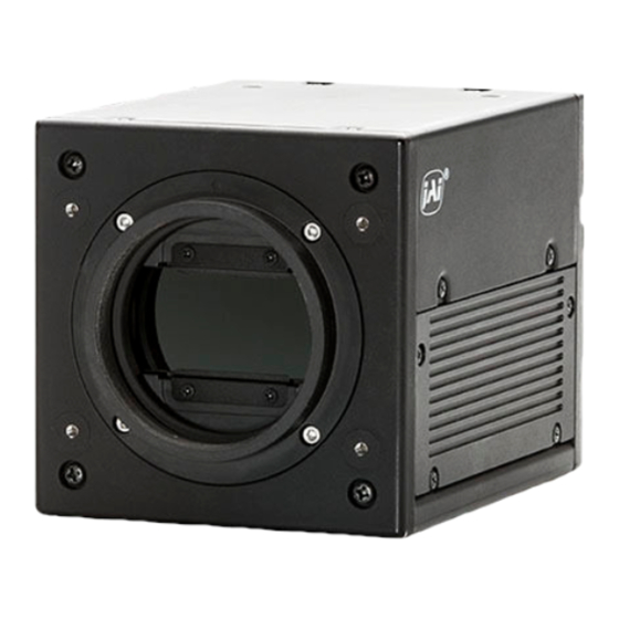
Page 7: Parts Identification
WA-1000D-CL Parts Identification 1 Lens mount (M52 mount) Mount an M52 lens here. Before mounting a lens, be sure to refer to “Step 2: Connecting Devices” (page 13) and confirm the ™ precautions for attaching a lens and the supported lens types. - Page 8 WA-1000D-CL 2 DC IN / trigger IN connector (12-pin round) Connect the cable for a power supply (sold separately) or for DC IN /trigger IN here. HR-10A-10R-12PB (71) (Hirose Electric or equivalent) Input/ Pin No. Signal Description output DC IN...
- Page 9 WA-1000D-CL Channel 2 (used during Connector Dual Base 2ch 8-/10-bit output) Input/ Pin No. Signal Description output 1, 14 Shield 2 (-), 15 (+) TxOUT0 Data output 3 (-), 16 (+) TxOUT1 Data output 4 (-), 17 (+) TxOUT2 Data output...
- Page 10 WA-1000D-CL LED status and camera status Light Status POWER/TRIG LED Camera initializing. Lit amber Operational and no triggers being input. Lit green Operational and triggers being input. Blinking green ™ The blinking interval is not related to the actual input interval of the external trigger.
-
Page 11: Preparation
WA-1000D-CL Preparation Preparation Flow Step 1 Installing the Software (first time only) Install the software for configuring and controlling the camera (JAI SDI) on the computer. Step 2 Connecting Devices Connect the lens, cables, AC adapter, computer, and other devices. - Page 12 WA-1000D-CL v Clear the [JAI GigE Vision Filter Driver] checkbox, and save. Verify the settings for using Camera Link. The GO-1000D-CL supports GenIcam and Gen-CP. Check the following settings when controlling the camera via JAI SDK. Checking the frame grabber board’s settings Settings must be configured on the frame grabber board to enable Gen-CP support.
-
Page 13: Step 2: Connecting Devices
WA-1000D-CL v Check that the [JAI_GenCP_Camera_Link] and [Camera Link Transport Layer] settings are configured as follows. Step 2: Connecting Devices Connect the lens, Camera Link cable, AC adapter, and other necessary devices. Attach the lens in a clean environment to prevent dust from adhering to the unit. - Page 14 WA-1000D-CL 1 Lens • M52-mount lenses with lens mount protrusions of 13 mm or less can be attached. 13 mm or less Lens mount protrusion Lens Caution • The maximum performance of the camera may not be realized depending on the lens.
-
Page 15: Step 3: Verifying The Camera Connection Status
WA-1000D-CL Step 3: Verifying the Camera Connection Status When the necessary devices are connected and power is supplied to the camera, the POWER/TRIG LED at the rear of the camera lights amber, and initialization of the camera starts. When initialization is complete, the POWER/TRIG LED lights green. -
Page 16: Control Via External Triggers
WA-1000D-CL Control via External Triggers When Controlling the Exposure Time Using Specified Exposure Times When [Device TG Mode] is set to [Async] (not synced), configure [JAI Custom Control] - [Acquisition Control Selector] as follows. Item Setting value / selectable range... -
Page 17: Control Without External Triggers
WA-1000D-CL Set [Exposure Mode] to [Trigger Width] . When you select [Trigger Width], [Trigger Mode] will automatically be set to [On]. Set [Trigger Selector] to [Line Start]. ([Line Start] is the default setting.) If necessary, change the [Trigger Source] and [Trigger Activation] settings. -
Page 18: Step 5: Adjusting The Image Quality
WA-1000D-CL Step 5: Adjusting the Image Quality To maximize the performance of the camera, configure its basic function in the following order. Configure the line rate (exposure time and shutter). ❖ For details on this setting, “Variable Line Rate” (page 33) and “Electronic Shutter” (page 34). -
Page 19: To Save User Settings
WA-1000D-CL ■ To save user settings Stop image capture. Expand [User Set Control] and select the save destination ([User Set1] to [User Set3]) in [User Set Selector]. Note The factory default setting values are stored in [Default] and cannot be overwritten. -
Page 20: Basic Function Matrix
WA-1000D-CL Basic Function Matrix The combinations of settings for the basic functions that can be used together are as follows. Shading MODE Gain Offset (automatic level correction Test Auto Line control) pattern Rate Exposure Trigger Master Individual Individual FLAT Gain... -
Page 21: Main Functions
WA-1000D-CL Main Functions Camera Output Formats Camera Link Output Ports ■ 2-ch For 8-bit (Base Configuration: 24-bit RGB) Input signal Camera Link output Port A Output from R and G of 24-bit RGB Port B Port C B-ch not used... -
Page 22: Camera Link Bit Assignments
WA-1000D-CL For 10-bit / 12-bit Input signal Camera Link output Port A CameraLink1 Port a, b Port B Port C Input signal Camera Link output Port D CameraLink2 Port d, e Port E Port F Camera Link Bit Assignments The camera is compatible with the Camera Link standard. The bit assignments are as follows. -
Page 23: Video Output Timing Diagram
WA-1000D-CL 2-ch Dual base Port / Connector 8-bit × 2 10-bit × 2 12-bit × 2 10-bit 12-bit signal name 8-bit output output output output output output × × × × × × Tx25 FVAL × × × × ×... -
Page 24: Exposure Mode
WA-1000D-CL Exposure Mode The following operation modes are available on the camera. Operation mode Command Exposure Mode Trigger Mode Timed ™ For details on operation mode and function combinations, see “Basic Function Matrix” (page 20). Image Output Timing Horizontal Timing ■... -
Page 25: Shortest Repetition Period For Triggers
WA-1000D-CL Shortest Repetition Period for Triggers Trigger Mode ON, full resolution Shortest period (μs) Exposure Mode OFF Camera Link 12-pin Exposure Mode Timed Camera Link Exposure time + (25.48 - 20.38) 12-pin Camera Link 12-pin Shortest Trigger Pulse Width Trigger Mode ON... -
Page 26: When [Exposure Mode] Is [Timed]
WA-1000D-CL Spclk (Sensor Pixel clock): 149.92 ns (6.67 MHz) pclk (Cameralink Pixel clock): 18.74 ns (53.36 MHz: SPCLK × 8) Restrictions on trigger input periods and line rate conditions As the first video signal triggered after the power is turned on or immediately after the trigger interval is 2 ms or higher is significantly affected by dark currents, we do not recommend using the first line at the beginning for [Trigger Mode]. -
Page 27: When [Exposure Mode] Is [Trigger Width]
WA-1000D-CL ■ When [Exposure Mode] is [Trigger Width] Perform accumulation and scanning using triggers from an external source. The accumulation time depends on the pulse width of the supplied trigger. • Shortest trigger period: 25.48 μs • Acceptable input pulse width: 50 μs to 1.995 ms (during TTL Interface input);... - Page 28 WA-1000D-CL Exposure Active 20.38 us to 1995 us 5.1 us (min) 6 spclk 0.94 us ± 0.075 us (Sensor Video 1/8 tap) 128 spclk 19.189 us LVAL 25.3 us DATA 1024 pclk 19.189 us Spclk (Sensor Pixel clock): 149.92 ns (6.67 MHz) pclk (Cameralink Pixel clock): 18.74 ns (53.36 MHz: SPCLK ×...
-
Page 29: Pixel Sensitivity Correction
WA-1000D-CL Pixel Sensitivity Correction Correct variations between the sensor’s pixels. ™ Switching for this function is performed via serial communication. ™ This function is dependent on the operation mode. PRNU Correction Correct sensitivity variations between the sensor’s pixels. Level differences between taps will also be corrected simultaneously. -
Page 30: Gain Control
AnalogBaseGain setting value Scaling* -6 dB ± 1 dB -3 dB ± 1 dB 0 dB ± 1 dB (WA-1000D-CL default setting) 3 dB ± 1 dB (WAHA-1000D-CL default setting) * Sensitivity (all scaling values are TYP values) ̶ 30 ̶... -
Page 31: Analog Fine Gain
WA-1000D-CL ■ Analog fine gain Analog fine gain (AFG) is gain that is performed after the video signal passes through the CDS circuit and prior to ADC (analog digital conversion). This gain can be configured simultaneously for both ch1 and ch2 or individually for ch1 and ch2. -
Page 32: Γ0.45
WA-1000D-CL ■ γ0.45 The following sensitivity curve is available internally on the camera. In this mode, the same sensitivity curve is configured for ch1 and ch2. CCD output level Analog Signal Digital Out (8-bit each) Digital Out (10-bit each) Black Setup 3.6%, 25 mV... -
Page 33: To Perform The Shading Function
WA-1000D-CL ■ To perform the shading function The function is turned ON/OFF via serial communication. This function is not dependent on the operation mode, but is effective when used during actual use. ™ You can also save the setting and have it applied whenever the power is subsequently turned on. For details on saving the setting, see “Step 7: Saving the Settings”... -
Page 34: Auto Line Rate Configuration Function
WA-1000D-CL ™ You can also save the setting and have it applied whenever the power is subsequently turned on, but this requires addition operations. ™ Switching and settings storage for this function is performed via serial communication. ™ The black level will change depending on the line rate, so be sure to readjust the black level after changing the line rate or trigger period. -
Page 35: Test Pattern Function
WA-1000D-CL Test Pattern Function You can display the following types of test patterns. Video output is not possible while a test pattern is being executed. This function is not dependent on gain and offset values that have already been configured, and output is performed in the following states. -
Page 36: Rs-232C Command Control
Camera Link: 8- ⇔ 10-bit switching Miscellaneous Test pattern: ON ⇔ OFF ™ For details, refer to the JAI WA-1000D-CL Communication Protocols. Field Upgrade Function You can update the timing controller and firmware using the dedicated update tool via Camera Link serial communication. -
Page 37: Settings List
WA-1000D-CL Settings List For details on the ASCII Command List, visit the product page (WA-1000D-CL) on our website. Control Tool : Settings that can only be configured when image capture on the camera is stopped. Item Setting range Default value... - Page 38 WA-1000D-CL Item Setting range Default value Description Gain 1 to 3.572 Set the gain value by multipliers for the gain setting selected in [Gain Selector]. Gain Raw 0 to 308 Set the gain value for the gain setting selected in [Gain Selector].
- Page 39 WA-1000D-CL Item Setting range Default value Description Device TG Mode Sync, Sync Select whether to operate with Channel 1 Async and Channel 2 synced or unsynced. [Sync]: Synchronize Channel 1 and Channel 2. [Async]: Operate with Channel 1 and Channel 2 unsynchronized.
-
Page 40: Communication
WA-1000D-CL Communication ™ For details on the setting items, refer to the JAI Control Tool User’s Guide Item Setting range Default value Description Line Status — — Displays the connection status between the camera and Control Tool. Communication Port Set the connection port. -
Page 41: Miscellaneous
I want to restore the factory default settings. To restore the factory default settings, select [Load settings] in the [Settings] menu of the [WA-1000D-CL Control Tool] window, select [Factory] in the dialog box that appears, and click [OK]. -
Page 42: Specifications
WA-1000D-CL Specifications Image sensor Model G10768-1024DB (Hamamatsu Photonics) Effective pixels 1024 pixels Pixel size 25.0 μm × 25.0 μm Effective imaging lines 25.600 mm Pixel clock 6.67 Hz Camera Link clock 53.36 MHz Line rate Full pixel Total clock 1360 clk Line rate 25.48 μs (during Continuous / Internal... - Page 43 / ambient temperature 25°C) ™ Use a power supply that can provide 3 A or more. Lens mount WA-1000D-CL-M52: M52-mount standard ™ Lens mount protrusion length of 13 mm or less is supported. Flange back M52-mount: 46.5 mm (in air), tolerance: ±0.1 mm Optical axis accuracy Center ±0.1 mm (Max)
- Page 44 WA-1000D-CL Connectors / LEDs Camera Link Model: 10226-1A10PL × 2 Function: video output / communication / external trigger / ™ Positive polarity for EEN (polarity switching not possible) 12-pin Model: HR10A-10R-12PB (71) Function: power supply input / communication / external trigger / EEN ™...
-
Page 45: Block Diagram
WA-1000D-CL Block Diagram ̶ 45 ̶... -
Page 46: Spectral Response
WA-1000D-CL Spectral Response ̶ 46 ̶... -
Page 47: Dimensions
WA-1000D-CL Dimensions U4-40 : Fixed screw 4-M3 Depth 3.5 POWER / TRIG W.B. DC IN / TRIG M52 Mount 12-pin Connector 4-M4 Depth 6 Dimensional tolerance: ±0.3 mm Unit: mm ̶ 47 ̶... - Page 48 WA-1000D-CL Trademarks • Microsoft and Windows are trademarks or registered trademarks of Microsoft Corporation in the United States and other countries. • Intel and Intel Core are trademarks of Intel Corporation in the United States and other countries. Other system and product names described in this document are trademarks or registered trademarks of their respective owners.
-
Page 49: Index
WA-1000D-CL Index Numerics 12-pin 8 LED 10 Lens mount 7 LUT 31 AC adapter 14 Network card 11 Black level correction 33 Output format 41 Camera link bit assignments 22 Channel 2 9 Channel balancing 33 Parts identification 7 C-mount 14...
Need help?
Do you have a question about the WA-1000D-CL and is the answer not in the manual?
Questions and answers