Table of Contents
Advertisement
Quick Links
User Manual
SP-20000M-CXP2
SP-20000C-CXP2
CMOS Digital Progressive Scan
Monochrome and Color Camera
Document Version: 2.0
Date: 2024-02-16
Thank you for purchasing this product.
Be sure to read this documentation before use.
This documentation includes important safety precautions and instructions on how to operate the unit. Be sure to read this documentation to ensure
proper operation.
The contents of this documentation are subject to change without notice for the purpose of improvement.
© 2024 JAI
Advertisement
Table of Contents

Related Manuals for IAI SP-20000M-CXP2


Summary of Contents for IAI SP-20000M-CXP2
- Page 1 User Manual SP-20000M-CXP2 SP-20000C-CXP2 CMOS Digital Progressive Scan Monochrome and Color Camera Document Version: 2.0 Date: 2024-02-16 Thank you for purchasing this product. Be sure to read this documentation before use. This documentation includes important safety precautions and instructions on how to operate the unit. Be sure to read this documentation to ensure proper operation.
-
Page 2: Table Of Contents
SP-20000-CXP2 User Manual (Ver. 2.0) Table of Contents Table of Contents Table of Contents About Technical Note Notice/Warranty Notice Warranty Certifications CE Compliance Warning China RoHS Usage Precautions EMVA1288 Interface Frame Grabber Board Notes on Coaxial Cables Notes on Exportation Features Parts Identification ①... - Page 3 SP-20000-CXP2 User Manual (Ver. 2.0) Table of Contents Optical Interface Pulse Generator Pulse Generator Setting Parameters Sensor Layout Camera Output Format (Tap Geometry) Output Timing Horizontal Timing Horizontal Formats in Continuous Trigger Vertical Timing Continuous Trigger Vertical Timing ROI (Regional Scanning Function) ROI Setting Examples Mirroring Function Multi ROI Function...
-
Page 4: About Technical Note
SP-20000-CXP2 User Manual (Ver. 2.0) Table of Contents PIV (Particle Image Velocimetry) Sequence ROI Trigger Sequence ROI Setting Parameters Operation and Function Matrix Black Level Control Gain Control Gain Auto Balance White Auto LUT (Lookup Table) Gamma Function Shading Correction Blemish Compensation ALC (Automatic Level Control) Miscellaneous... -
Page 5: Notice/Warranty
CE Compliance As defined by the Directive 2004/108/EC of the European Parliament and of the Council, EMC (Electromagnetic compatibility), JAI Ltd., Japan declares that SP-20000M-CXP2 and SP-20000C- CXP2 comply with the following provisions applying to their standards. EN 61000-6-3 (Generic emission standard part 1) -
Page 6: Warning
JAI Ltd. Japan 상 호: JAI Ltd. Japan 기자재명칭: Industrial Camera 기자재명칭: Industrial Camera 모 델 명: SP-20000M-CXP2 모 델 명: SP-20000C-CXP2 제조자 및 제조국가: JAI Ltd., Japan / JAPAN 제조자 및 제조국가: JAI Ltd., Japan / JAPAN R-R-JAi-SP-20000M-CXP2 R-R-JAi-SP-20000M-CXP2 제조년월은 제품상자의 라벨을 참조하십시오. -
Page 7: China Rohs
物质或元素名称及含量表》如下. 有毒有害物质或元素 部件名称 六价铬 多溴联苯 多溴二苯醚 铅 汞 镉 (Cr (VI)) (PBB) (PBDE) (Pb) (Hg) (Cd) SP-20000M-CXP2 × 〇 〇 〇 〇 〇 SP-20000C-CXP2 〇:表示该有毒有害物质在该部件所有均质材料中的含量均在 GB/T 26572-2011规定的限量要求以下。 ×:表示该有毒有害物质至少在该部件的某一均质材料中的含量超出 GB/T 26572-2011规定的限量要求。 环保使用期限 电子信息产品中含有的有毒有害物质或元素在正常使用的条件下不会发生外 泄或突变、 电子信息产品用户使用该电子信息产品不会对环境造成严重污染 或对其人身、财产造成 严重损害的期限。 数字「15」为期限15年。 - 7 -... -
Page 8: Usage Precautions
SP-20000-CXP2 User Manual (Ver. 2.0) Usage Precautions Usage Precautions EMVA1288 With regard to signal-to-noise ratio in this manual, specifications measured by EMVA 1288 are used together with specifications by a traditional measurement method. EMVA 1288 is a more complete measurement that considers multiple noise sources, including random noise, pattern noise, and shading. -
Page 9: Features
This camera provides both high resolution and a high frame rate with excellent image quality for machine vision applications. The SP-20000M-CXP2 is a monochrome progressive scan CMOS camera and the SP-20000C-CXP2 is the equivalent Bayer mosaic progressive scan CMOS camera. - Page 10 SP-20000-CXP2 User Manual (Ver. 2.0) Features Vertical and horizontal binning on monochrome model Supports ROI (Region Of Interest) modes 0dB to +24dB gain control for both monochrome and color models. 299 μs (1/100,000) to 8 seconds exposure control in 1 μs step Auto exposure control Timed and trigger width exposure control PIV and sequential trigger modes for specific applications...
-
Page 11: Parts Identification
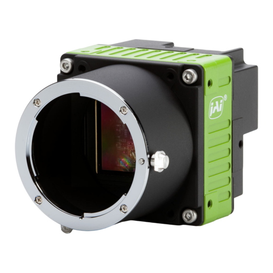
SP-20000-CXP2 User Manual (Ver. 2.0) Parts Identification Parts Identification Note: The above is an external view of the F-mount model; for an external view of the M42 mount, see " M42-Mount Model". ① Lens Mount (F-Mount or M42-Mount) ② AUX connector (10-Pin) ③... -
Page 12: ② Aux Connector (10-Pin)
SP-20000-CXP2 User Manual (Ver. 2.0) Parts Identification Cautions: The maximum performance of the camera may not be realized depending on the lens. Attaching a lens with a protrusion longer than 40.0 mm for the F-mount or 39.0 mm for the M42- mount may damage the lens or camera. -
Page 13: ③ Power/Trig Led
SP-20000-CXP2 User Manual (Ver. 2.0) Parts Identification ③ POWER/TRIG LED Indicates the power or trigger input status. Status Camera initializing. The light blinks once after initialization. The light also blinks while Lit amber changing the Link Configuration. Lit green Camera in operation in Continuous mode The camera is receiving external triggering. -
Page 14: ⑤ Link-1 / Link-2 Led
SP-20000-CXP2 User Manual (Ver. 2.0) Parts Identification 3. If power is supplied from both the 12-pin connector and CoaXPress, the power from the 12-pin is active. If power from the 12-pin is interrupted, the operation depends on how power was initially connected. -
Page 15: ⑦ ⑧ Mounting Holes (M3)
SP-20000-CXP2 User Manual (Ver. 2.0) Parts Identification ⑦ ⑧ Mounting Holes (M3) Use these holes when attaching an MP-42 tripod adapter plate (optional) or mounting the camera directly to a system. If you mount the tripod mounting plate, please use the provided screws. Top, Side and Bottom: M3, Depth 5 x 3 Front: M3, Dept 3 x 4 - 15 -... -
Page 16: Main Functions
SP-20000-CXP2 User Manual (Ver. 2.0) Main Functions Main Functions This chapter describes the camera's main functions. CoaXPress Interface Standard This camera uses CoaXPress as their interface. CoaXPress is a PLUG-AND-PLAY interface and connects the camera and the frame grabber board by coaxial cable(s). Its maximum transfer rate is 6.25 Gbps per one coaxial cable. - Page 17 Model Pixel format Link configuration Bit rate / cable Used BNC cable Mono 8/10/12 CXP6_X2 6.250 Gps Mono 8/10/12 CXP6_X1 6.250 Gps SP-20000M-CXP2 Mono 8/10/12 CXP3_X2 3.125 Gps Mono 8/10/12 CXP3_X1 3.125 Gps Bayer 8/10/12/RGB CXP6_X2 6.250 Gps Bayer 8/10/12/RGB CXP6_X1 6.250 Gps...
-
Page 18: Gpio (Digital Input/Output Settings)
SP-20000-CXP2 User Manual (Ver. 2.0) Main Functions GPIO (Digital Input/Output Settings) The camera can input/output the following signals to and from external input/output connectors. Line Selector Line Selector Description Line 1 - TTL OUT 1 ③ POWER/TRIG LED: Pin 9 Line 2 - OPT OUT 1 ③... - Page 19 SP-20000-CXP2 User Manual (Ver. 2.0) Main Functions Line Mode Indicates the status of the item selected in Line Selector. (INPUT or OUTPUT) GenICam Access Values Name Line Line 1 - TTL OUT 1, Line 2 - OPT OUT 1, Line4 - TTL In 1, Line5 - Opt In 1, Line7 - CXP In, Line8 - TTL Out 2, Line9 Selector - TTL Out 3, Line10 - TTL In 2, Line11 - LVDS In, NAND 0 In 1, NAND 0 in 2, NAND 1, In 1 NAND 1 in 2 Line...
- Page 20 SP-20000-CXP2 User Manual (Ver. 2.0) Main Functions GPIO GPIO is a general interface for input and output and controls the I/O for trigger signals and other valid signals and pulse generators. By using this interface, you can control an external light source, make a delay function for an external trigger signal, or make a precise exposure setting together with a PWC trigger.
-
Page 21: Input And Output Matrix Table
SP-20000-CXP2 User Manual (Ver. 2.0) Main Functions Input and Output Matrix Table The relation between input and output is as follows. Trigger Selector Line Selector Pulse Generator Selector Frame Acq. OPTO NAND NAND NAND NAND Pulse Pulse Pulse Pulse Source Signal Acq.End Start Start... -
Page 22: Optical Interface
SP-20000-CXP2 User Manual (Ver. 2.0) Main Functions Optical Interface This camera is equipped with opto-isolated inputs and outputs, providing galvanic separation between the camera’s inputs/outputs and peripheral equipment. In addition to galvanic separation, the opto- isolated inputs and outputs can cope with a wide range of voltages; the voltage range for inputs is +3.3V to +24V DC whereas outputs will handle +5V to +24V DC. - Page 23 SP-20000-CXP2 User Manual (Ver. 2.0) Main Functions Characteristics of optical interface The relationship of the input signal to the output signal through the optical interface is as follows. User Power (VCC) 270Ω 3.3V Time Delay Rise TDR (us) 0.54 0.54 0.62 0.68 Rise Time RT (us)
-
Page 24: Pulse Generator
SP-20000-CXP2 User Manual (Ver. 2.0) Main Functions Pulse Generator This camera has a frequency divider using the sensor clock as the basic clock and four pulse generators. In each Pulse Generator, various Clear settings are connected to GPIO. The following shows Pulse Generator default settings. Display Name Value Clock Pre-scaler... - Page 25 SP-20000-CXP2 User Manual (Ver. 2.0) Main Functions Pulse Generator Length Set the counter up value for the selected pulse generator. If Repeat Count value is “0”, and if Pulse Generator Clear signal is not input, the pulse generator generates the pulse repeatedly until reaching this count up value.
- Page 26 SP-20000-CXP2 User Manual (Ver. 2.0) Main Functions Pulse Generator Clear Sync Mode Set the count clear method for the selected pulse generator. In case of Async Mode, if the clear signal is input during the length setting value, the counter will stop counting according to the clear signal input.
-
Page 27: Pulse Generator Setting Parameters
SP-20000-CXP2 User Manual (Ver. 2.0) Main Functions Pulse Generator Setting Parameters Display Name Value Clock Pre-scaler 1 to 4096 Pulse Generator Clock [Pixel Clock:39.16MHz]÷[Clock Per-scaler] (MHz) Pulse Generator Pulse Generator 0 ~ 3 Selector Pulse Generator Length 1 to 1048575 Pulse Generator Length ([Clock Source]÷[Clock Per-scaler]) x [Pulse Generator Length]... -
Page 28: Sensor Layout
SP-20000-CXP2 User Manual (Ver. 2.0) Main Functions Notes: 1. If Pulse Generator Repeat Count is set to "0", the pulse generator works in free-running mode. 2. The output of the same pulse generator cannot be connected to Clear input. Sensor Layout The CMOS sensors used on this camera have the following pixel layout. -
Page 29: Camera Output Format (Tap Geometry)
SP-20000-CXP2 User Manual (Ver. 2.0) Main Functions Camera Output Format (Tap Geometry) This camera supports the following output format. Camera Output Format Pixel Format 1X–1Y 8 bit, 10 bit, 12 bit, RGB 8-bit Note: The camera output description is based on GenICam SFNC Ver.1.5.1. 1X–1Y 1X–1Y is 1-tap readout system specified in GenICam Tap Geometry and it outputs as the following. -
Page 30: Output Timing
SP-20000-CXP2 User Manual (Ver. 2.0) Main Functions Output Timing Horizontal Timing The horizontal frequency depends on the link configuration. The following chart and tables explain the details. On this camera, the horizontal frequency does not change when horizontal binning is effective, and therefore, the frame rate is not increased. -
Page 31: Horizontal Formats In Continuous Trigger
SP-20000-CXP2 User Manual (Ver. 2.0) Main Functions Horizontal Formats in Continuous Trigger Horizontal Formats (1/2) Note: Binning 1 = Off, 2 = On (a) LVAL (b) LVAL Non- (c) H- (d) Exposure Active Start to Binning Step Active Active Offset LVAL Active Start Offset Offset... - Page 32 SP-20000-CXP2 User Manual (Ver. 2.0) Main Functions Horizontal Formats (2/2) Note: Binning 1 = Off, 2 = On Binning 1Line Total Clock Horizontal Frequency Horizontal Period Width Offset X Height Offset Y [Unit: Clock] [Unit: kHz] [Unit: us] 5120 3840 320.5 124.805 8.013...
-
Page 33: Vertical Timing
SP-20000-CXP2 User Manual (Ver. 2.0) Main Functions Vertical Timing In Continuous Trigger operation, the output timing relation is as follows. This camera supports the H-Binning and V-Binning functions, but the frame rate is not increased. - 33 -... -
Page 34: Continuous Trigger Vertical Timing
SP-20000-CXP2 User Manual (Ver. 2.0) Main Functions Continuous Trigger Vertical Timing Vertical formats in Continuous Trigger (1/2) Note: Binning 1 = Off, 2 = On (B) FVAL Non- (C) V- (D) Exposure Binning Acquisition FVAL Active Active Offset Time (Min) Frame Offset Offset Unit:... - Page 35 SP-20000-CXP2 User Manual (Ver. 2.0) Main Functions Vertical formats in Continuous Trigger (2/2) (F) Exposure End Frame Binning ROI (E) Exposure Time (Max.) to FVAL Active Acquisition Rate Start Frame Rate Offset Offset Unit: Width Height V Unit: Hz Unit: us Unit: us Line 5120...
-
Page 36: Roi (Regional Scanning Function)
SP-20000-CXP2 User Manual (Ver. 2.0) Main Functions ROI (Regional Scanning Function) On this camera, a subset of the image can be output by setting Width, Height, Offset-X, and Offset-Y. On this camera, the minimum width is “8” and minimum height is “2”. Setting Example: 1 (Binning OFF) Setting Example: 2 (Binning On - Mono Model Only) Binning Horizontal = 1... -
Page 37: Roi Setting Examples
SP-20000-CXP2 User Manual (Ver. 2.0) Main Functions ROI Setting Examples Note: Binning 1 = Off, 2 = On Binning Width and Offset X Step Width Height Height Offset CXP6 _X1 Offset X Offset Y Offset Offset CXP6 CXP3 Step Y Step Width Height or CXP3 _... -
Page 38: Mirroring Function
SP-20000-CXP2 User Manual (Ver. 2.0) Main Functions Mirroring Function This camera has the ability to reverse the image vertically, horizontally, or both vertically and horizontally. If ROI readout is used, ROI image can be read out after the image is reversed. Examples of Mirror function settings is shown below. -
Page 39: Multi Roi Function
SP-20000-CXP2 User Manual (Ver. 2.0) Main Functions Multi ROI Function This function divides one frame image into a maximum of 8 images vertically and reads out all areas in one frame. In this function, width is the same for all 8 images. The Multi ROI function is enabled if Video Sending Mode is set to “Multi ROI”. - Page 40 SP-20000-CXP2 User Manual (Ver. 2.0) Main Functions ROI setting explanation if Multi ROI Index Max is set to 4 The figure below shows the video output with the above example settings. Video output of Multi ROI Caution: If Multi ROI function is used, the frame grabber board that is used should be set as follows.
-
Page 41: Digital Output Bit Allocation
SP-20000-CXP2 User Manual (Ver. 2.0) Main Functions Digital Output Bit Allocation Digital Out CMOS Out 8bit 10bit 12bit Black 8LSB 32LSB 128LSB Mono / Color 100% 222LSB 890LSB 3560LSB Mono / Color 115% 225LSB 1023LSB 4095LSB Bit Allocation (10-bit) - 41 -... -
Page 42: Acquisition Control (Change The Frame Rate)
SP-20000-CXP2 User Manual (Ver. 2.0) Main Functions Acquisition Control (Change the Frame Rate) With Trigger OFF and in free-running mode, the default frame rate of the camera is based on the specified ROI. The smaller the ROI, the faster the default frame rate. However, it is possible to specify a free-running frame rate that is slower than the default rate. -
Page 43: Calculation Of Frame Rate (In Continuous Trigger Mode)
Main Functions Relationship between Link Configuration and Acquisition Frame Rate Model Image Size Link Configuration Pixel Format Acquisition Frame Rate (Max. Value) CXP6_X2 CXP6_X1 SP-20000M-CXP2 5120 x 3480 Mono 8/10/12 CXP3_X2 CXP3_X1 Bayer RG 8/10/12 CXP6_X2 RGB8 Bayer RG 8/10/12... -
Page 44: Exposure Mode
SP-20000-CXP2 User Manual (Ver. 2.0) Main Functions Exposure Mode This camera has three Exposure modes (Off, Timed, TriggerWidth). Use the AcquisitionControl settings to perform operations and settings for exposure. Exposure Operation Mode Exposure control is not performed (free-running operation). The exposure time is the longest possible time within the operating conditions such as the frame rate. -
Page 45: Exposuretime
8 secs of exposure time. SP-20000M-CXP2: Up to 15 ºC of ambient temperature SP-20000C-CXP2: Up to 5ºC of ambient temperature - 45 -... -
Page 46: Behavior If Trigger Overlap Is Set To Readout
SP-20000-CXP2 User Manual (Ver. 2.0) Main Functions Associated GenICam Register Information GenICam Name Access Values Category Exposure Mode Off, Timed, TriggerWidth Acquisition Control Exposure Time 10 to 8000000 [us] Acquisition Control Exposure Time Raw 10 to 8000000 [us] Acquisition Control Behavior if Trigger Overlap is set to Readout On this camera, if the accumulation of the next frame starts while the current image is read out, the varied value of accumulation time is changed to 1 Line period inside the camera. - Page 47 SP-20000-CXP2 User Manual (Ver. 2.0) Main Functions As an example, the following is for the continuous trigger operation. - 47 -...
-
Page 48: Exposureauto
SP-20000-CXP2 User Manual (Ver. 2.0) Main Functions ExposureAuto An automatic exposure control function using Exposure. This function works only when Exposure Mode is Timed (EPS), and brightness can be controlled by ALC Reference. There are three modes: OFF, Once and Continuous. ExposureAuto Description No exposure control... -
Page 49: Trigger Control
SP-20000-CXP2 User Manual (Ver. 2.0) Main Functions Trigger Control Trigger Source can be selected in Trigger Selector. On this camera, the trigger source can be selected from Frame Start, Acquisition Start, and Acquisition End. Trigger Trigger Exposure Trigger JAI Custom Trigger Description Selector Mode... - Page 50 SP-20000-CXP2 User Manual (Ver. 2.0) Main Functions Trigger Activation This command can select how to activate the trigger. Rising edge: At the rising edge of the pulse, the trigger is activated. Falling edge: At the falling edge of the pulse, the trigger is activated. Level High: During the high level of trigger, the accumulation is activated Level Low: During the low level of trigger, the accumulation is activated Note: If Exposure Mode is set to Trigger Width, Level High or Level Low must be used.
-
Page 51: Normal Continuous Operation (Timed Exposure Mode/Trigger Mode Off)
SP-20000-CXP2 User Manual (Ver. 2.0) Main Functions Normal Continuous Operation (Timed Exposure Mode/Trigger Mode OFF) This is used for applications which do not require triggering. For the video timing, refer to "Output Timing". Typical Minimum interval Time (Min. Trigger Period) Readout Mode CXP6_X2 CXP6_X1, CXP3_X2... -
Page 52: Timed (Eps) Mode
SP-20000-CXP2 User Manual (Ver. 2.0) Main Functions Timed (EPS) Mode This mode allows a single image frame to be captured with a preset exposure time by using the external trigger. An additional setting determines if the trigger pulse can be accepted during the exposure period. -
Page 53: Trigger Overlap = Off (Timed Mode)
SP-20000-CXP2 User Manual (Ver. 2.0) Main Functions Trigger Overlap = Off (Timed Mode) Note: The trigger pulse is accepted during Frame Trigger Wait being active if the trigger overlap is OFF. When the trigger is accepted, the trigger wait is inactive until the readout is completed. Tap Geometry Vertical Binning Exposure Active Signal source CXP6_X2 CXP6_X1, CXP3_X2... - Page 54 SP-20000-CXP2 User Manual (Ver. 2.0) Main Functions Minimum trigger interval calculation formula (Trigger Overlap: OFF) Link Binning Trigger Mode="On", Exposure Mode="Timed", Trigger Overlap="Off" [Unit: Configuration Geometry Vertical 1 (Off) ROUNDDOWN( ((([Height]+1) x 320.5) + 12205 ) ÷ 40MHz x 10^6) + 10us CXP6_X2 1X –...
-
Page 55: Trigger Overlap = Readout (Timed Mode)
SP-20000-CXP2 User Manual (Ver. 2.0) Main Functions Trigger Overlap = Readout (Timed Mode) Note: If the trigger overlap is Readout mode, Frame Trigger Wait is active on FVAL period of the previous trigger. In this period, the next trigger can be accepted. After receiving this trigger pulse, Frame Trigger Wait becomes inactive. - Page 56 SP-20000-CXP2 User Manual (Ver. 2.0) Main Functions Minimum trigger interval calculation formula (Trigger Overlap: Readout) Link Binning Conditions: Trigger Mode = "On", Exposure Mode = "Timed", Trigger Overlap = "Readout" Configuration Vertical (Unit: us) If ROUNDDOWN(((([Height]+1) x 320.5) + 12205 ) ÷ 40MHz x 10^6) + 10 - 260 ≧ [Exposure Time] Result= ROUNDDOWN(((([Height]+1) x 320.5) + 12205 ) ÷...
-
Page 57: Gpio Ttl Output Timing (Trigger Overlap = Off, Timed Mode)
SP-20000-CXP2 User Manual (Ver. 2.0) Main Functions If the trigger overlap is set at ―Readout‖ and the trigger period is set such that ( the trigger period (μs) – 260μs) is shorter than the exposure time, the exposure operation does not work properly and as a result, the proper image is not displayed. - Page 58 SP-20000-CXP2 User Manual (Ver. 2.0) Main Functions CXP6_X1 Description CXP6_X2 CXP3_X1 Note CXP3_X2 If Exposure Time = 10. 8.61 us 8.61 us 8.68 us (10.05 Exposure Active (10.03 us) (10.03 us) ( ) is the exposure time inside camera 30.74 ms 61.53 ms 123.07 ms If Binning off and Height=3840 (Varies by the...
-
Page 59: Gpio Ttl Output Timing (Trigger Overlap = Readout, Timed Mode)
SP-20000-CXP2 User Manual (Ver. 2.0) Main Functions GPIO TTL Output Timing (Trigger Overlap = Readout, Timed Mode) GPIO Timing (Overlap = Readout) CXP6_X1 Description CXP6_X2 CXP3_X1 Note CXP3_X2 Frame Start Trigger to 1.063 us Frame Trigger Wait Falling 860 ns 840.00 ns (±25ns) Edge... - Page 60 SP-20000-CXP2 User Manual (Ver. 2.0) Main Functions CXP6_X1 Description CXP6_X2 CXP3_X1 Note CXP3_X2 This may vary by binning setting and ROI setting. The FVAL Falling Edge to 1.02 us 1.03 us 270 ns phase of Frame Active End Edge may vary by 1us Frame Active Falling Edge against FVAL Active End.
-
Page 61: Triggerwidth Mode
SP-20000-CXP2 User Manual (Ver. 2.0) Main Functions TriggerWidth Mode In this mode, the exposure time is equal to the trigger pulse width. Accordingly, longer exposure times are supported. Additional settings determine if the trigger pulse can be accepted during the exposure period. -
Page 62: Trigger Overlap = Off (Triggerwidth Mode)
SP-20000-CXP2 User Manual (Ver. 2.0) Main Functions Trigger Overlap = OFF (TriggerWidth Mode) Note: The trigger pulse is accepted during Frame Trigger Wait being active if the trigger overlap is OFF. When the trigger is accepted, the trigger wait is inactive until the readout is completed. Vertical Exposure Active Signal CXP6_X1, CXP3_... - Page 63 SP-20000-CXP2 User Manual (Ver. 2.0) Main Functions Vertical Exposure Active Signal CXP6_X1, CXP3_ CXP6_X2 CXP3_X1 Binning Source 0.780 us ~ 0.830 0.750 us ~ 0.800 0.740 us ~ 0.800 TTL Out Actual Exposure time difference 2.190 us ~ 2.250 2.160 us ~ 2.240 2.240 us ~ 2.260 Inside Camera Notes:...
-
Page 64: Trigger Overlap = Readout (Triggerwidth Mode)
SP-20000-CXP2 User Manual (Ver. 2.0) Main Functions Trigger Overlap = Readout (TriggerWidth Mode) Note: If the trigger overlap is Readout mode, Frame Trigger Wait is active during FVAL period of the previous trigger. In this period, the next trigger can be accepted. After receiving this trigger pulse, Frame Trigger Wait becomes inactive. - Page 65 SP-20000-CXP2 User Manual (Ver. 2.0) Main Functions Vertical Exposure Active Signal CXP6_X2 CXP6_X1 CXP3_X2 CXP3_X1 Binning source TTL Out -7.180 us ~ 0.840 us -15.210 us ~ 1.220 us -31.240 us ~ 0.870 us (b)-(a): Exposure Difference Inside Camera -5.730 us ~ 2.290 us -13.770 us ~ 2.270 us -29.780 us ~ 2.320 us Notes: The jitter from the trigger occurs at both the exposure start edge and exposure end edge.
- Page 66 SP-20000-CXP2 User Manual (Ver. 2.0) Main Functions Link Configuration Binning Vertical Conditions: PWC Trigger / Trigger Overlap = Readout [Unit: us] ROUNDDOWN(((([Height]+1) x 641) + 12205 ) ÷ 40MHz x 10^6) +10 - 260 ≧ [Trigger Pulse Width] Result = ROUNDDOWN((((([Height]+1) x 641) + 12205 ) ÷ 40MHz x 10^6)+ [Trigger Pulse Width: 10us~]) 1 (Off) ROUNDDOWN(((([Height]+1) x 641) + 12205 ) ÷...
-
Page 67: Piv (Particle Image Velocimetry)
SP-20000-CXP2 User Manual (Ver. 2.0) Main Functions PIV (Particle Image Velocimetry) The Particle Image Velocimetry mode can be used in applications where 2 images need to be taken with a very short time interval. It can only be used with strobe flash as illumination. The first accumulation time is 10 us to 2 sec. - Page 68 SP-20000-CXP2 User Manual (Ver. 2.0) Main Functions Notes: The exposure time for the first frame (te1) can be set by Exposure Time. The second exposure time (te2) varies by ROI setting and Binning setting but is not affected by Exposure Time setting. PIV trigger Mode Specifications (CXP-6_X2) Exposure Active Description...
- Page 69 SP-20000-CXP2 User Manual (Ver. 2.0) Main Functions Exposure Active Description Time (CXP6_X2) Signal Source ≒ 1 frame TTL Out (1) V-Binning Off = ((([Height]×320.5) - 0.5) ÷ 40MHz) - 2.05 us + 128.77 us Internal = ((([Height]×320.5) - 0.5) ÷ 40MHz) - 0.35 us + 128.78 us Second exposure time (2) V-Binning On TTL Out...
- Page 70 SP-20000-CXP2 User Manual (Ver. 2.0) Main Functions PIV trigger mode specifications (CXP-6_X1, CXP3_X2) Exposure Active Description Time (CXP6_X1, CXP3_X2) Signal Source TTL Out 2.11 us Exposure Beginning delay Internal 400 ns~ 430 ns 10us ~ ≒ 1 Frame ([Height]=3840 : 66417us Max) = [Exposure Time Settings] First exposure time period TTL Out...
- Page 71 SP-20000-CXP2 User Manual (Ver. 2.0) Main Functions Exposure Active Description Time (CXP6_X1, CXP3_X2) Signal Source (1) V-Binning Off Trigger Period (Min.) = (((([Height]+0.5)×641)-0.5) x 2Frame ÷ 40MHz) +[Exposure Time] + 305.22 us + 434.00 us (2) V-Binning On = (((([Height]+0.5)×1282)-0.5) x 2Frame ÷ 40MHz) +[Exposure Time] + 305.22 us + 434.00 us 2nd FVAL Active End ~ 0 Line...
-
Page 72: Sequence Roi Trigger
SP-20000-CXP2 User Manual (Ver. 2.0) Main Functions Exposure Active Description Time (CXP3_X1) Signal Source TTL Out V-Binning Off / V-Binning On = 610.19 us 2nd Frame Readout Delay Internal V-Binning Off / V-Binning On = 610.43 us V-Binning Off / V-Binning On = 739.00 us FVAL Non-Active (1) V-Binning Off = 23.1 Line (2) V-Binning On = 11.5 Line... - Page 73 SP-20000-CXP2 User Manual (Ver. 2.0) Main Functions Command Sequence In this mode, after the acquisition starts, the index table is executed by the external trigger which sets the index according to the Next Sequence Index Command. In this case, Sequence ROI Frame Count and Sequence ROI Next Index commands in the index table are ignored.
-
Page 74: Sequence Roi Setting Parameters
SP-20000-CXP2 User Manual (Ver. 2.0) Main Functions Default Sequence Index Table Gain Selector Binning Sequence ROI Offset Offset Exposure Black Frame Next Width Height Gain Index Time Level Enable Count Indes Red Blue (ALL) Index 0 ~ 9 5120 3840 180000 Index 0 (Off) - Page 75 In Sequence ROI Gain Selector, the gain settings for each index are available. Sequence ROI Gain SP-20000C-CXP2: Gain (ALL), Red, and Blue can be set. Selector SP-20000M-CXP2: Only Gain is displayed and can be set. Sequence 10 ~ Acquisition Exposure Time setting is available for each index.
- Page 76 SP-20000-CXP2 User Manual (Ver. 2.0) Main Functions Setting Setting Description Item Range If Trigger Sequence is selected, and if there is an entry in the Index Table whose Sequence ROI Next Index is set to OFF, the value of Sequence Repetition is valid. Then, it becomes possible to repeat the Index Table as set in Sequence Repetition.
- Page 77 SP-20000-CXP2 User Manual (Ver. 2.0) Main Functions Flow chart of Trigger Sequence - 77 -...
-
Page 78: Operation And Function Matrix
SP-20000-CXP2 User Manual (Ver. 2.0) Main Functions Operation and Function Matrix Video Send V- H- Mode Exposure Trigger Trigger Exposure Auto White Auto Auto Trigger Binning Binning Mode Mode Option Control Balance Gain Exposure Overlap Multi Sequence Timed Timed Trigger Width Timed Notes:... -
Page 79: Black Level Control
SP-20000-CXP2 User Manual (Ver. 2.0) Main Functions Black Level Control This function adjusts the setup level. Variable range: -256 to 255 LSB (at 12-bit output) Model Black Level Selector Black Level Monochrome Black Level All -256 ~ +255 Black Level All -256 ~ +255 Color Black Level Red... -
Page 80: Gain Control
SP-20000-CXP2 User Manual (Ver. 2.0) Main Functions Gain Control This camera can adjust the master gain level (DigitalGainAll) from x1 (0dB) to 16 times (+24dB) using x1 (0dB) as the reference (Factory default). On the color model, the master gain level (DigitalGainAll) can be adjusted from x1 (0dB) to 16 times (+24dB) and R and B gains can be adjusted in the range of 0.45 times (-7dB) to 3.16 times (+ 10dB) using the master gain as the reference. -
Page 81: Gain Auto
SP-20000-CXP2 User Manual (Ver. 2.0) Main Functions Gain Settings Model Gain Selector Gain Monochrome Digital All 100 ~ 1600 (0dB ~ 24dB) Digital All 100 ~ 1600 (0dB ~ 24dB) Color Digital Red -4533 ~ +17713 (-7dB ~ +10dB) Digital Blue -4533 ~ +17713 (-7dB ~ +10dB) Gain Auto This provides automatic control of the gain level. -
Page 82: Balance White Auto
SP-20000-CXP2 User Manual (Ver. 2.0) Main Functions Balance White Auto This is a function to enable the auto white balance by using R and B gain controls. Setting Range Description Off (Default) Adjust manually. BalanceWhiteAuto Once Performs auto white balancing once when this function is called. Continuous Continuously adjusts white balance. -
Page 83: Lut (Lookup Table)
SP-20000-CXP2 User Manual (Ver. 2.0) Main Functions LUT (Lookup Table) This function can be used to convert the input to the desired output characteristics. The Look-Up Table (LUT) has 256 points for setup. The output level can be created by multiplying the gain data by the input level. -
Page 84: Gamma Function
SP-20000-CXP2 User Manual (Ver. 2.0) Main Functions Gamma Function This command is used to set gamma between gamma 0.45 and gamma 1.0 (OFF). 16 steps are provided. The gamma value is an approximate value. Shading Correction This function compensates for shading (non-uniformity) caused by the lens or the light source used. This compensation can be performed even if shading issues are not symmetrical in horizontal and/or vertical directions. - Page 85 SP-20000-CXP2 User Manual (Ver. 2.0) Main Functions Color Shading (Color model only) R channel and B channel are adjusted to match with G channel characteristics. The block grid for compensation is 20 blocks (H) x 15 blocks (V) and each block contains 256 x 256 pixels. The complementary process is applied to produce the compensation data with less error.
-
Page 86: Blemish Compensation
SP-20000-CXP2 User Manual (Ver. 2.0) Main Functions Blemish Compensation This camera has a blemish compensation circuit. This function compensates blemishes on the CMOS sensor (typically pixels with extremely high response or extremely low response). This applies to both monochrome and color versions. Pixels that fulfill the blemish criteria can be compensated by averaging the data from pixels in both adjacent columns and, in the case of the color model, the defective pixels can be compensated by averaging the data from the same Bayer color pixels in adjacent columns. -
Page 87: Alc (Automatic Level Control)
SP-20000-CXP2 User Manual (Ver. 2.0) Main Functions ALC (Automatic Level Control) On this camera, auto gain (AGC) and auto exposure (ASC) can be combined to provide a wide ranging automatic exposure control from dark to bright or vice versa. The functions are applied in the sequence shown below and if one function is disabled, the remaining function will work independently. - Page 88 SP-20000-CXP2 User Manual (Ver. 2.0) Main Functions Detection Area High High HighLeft HighRight MidLeft MidRight MidHigh MidHigh MidHigh MidHigh Left MidLeft MidRight Right MidLow MidLow MidLow MidLow Left MidLeft MidRight Right LowLeft LowRight MidLeft MidRight - 88 -...
-
Page 89: Miscellaneous
SP-20000-CXP2 User Manual (Ver. 2.0) Miscellaneous Miscellaneous Troubleshooting Check the following before requesting help. If the problem persists, contact your local JAI distributor. Power Supply and Connections Issue: The POWER/TRIG LED remains lit amber and does not turn green, even after power is supplied to the camera. -
Page 90: Specifications
SP-20000-CXP2 User Manual (Ver. 2.0) Miscellaneous Specifications Item Description Scanning System Progressive scan, 1 tap Synchronization Internal CoaXPress (JIIA NIF-011-2010 CoaXPress Standard first edition) 6.25 Gbps, 2 Interface Link PoCXP compliance Monochrome: 35mm Monochrome CMOS Image Sensor Color: 35mm Bayer color CMOS Aspect Ratio Aspect Ratio: 4:3;... - Page 91 SP-20000-CXP2 User Manual (Ver. 2.0) Miscellaneous Item Description Mono: 10-bit output format, 16.05 p (λ = 525 nm) 40.24dB EMVA 1288 Parameters Absolute sensitivity Maximum SNR Color: 10-bit output format, 18.14 p (λ = 530 nm) 38.32dB Image Output Format Digital Full Image: 5120 (h) x 3840(v) Height: 2 ~ 3840 line, 2 Line/step Offset Y: 0 ~ 3838 line, 2 line/step...
- Page 92 SP-20000-CXP2 User Manual (Ver. 2.0) Miscellaneous Item Description Reference: 33.5LSB 10bit (Average of 100*100) Setting Range: -256 ~ 255LSB 10bit Black Level Adjustment Resolution: 1 STEP = 1LSB Mode: Auto / Limit / Fix Limit: 0% ~ 30 % Manual Adjustment Range: 0dB ~ +24dB, 0.01dB/step WB Gain*: R / B : -7dB ~ +10dB, 0.01dB/step Gain Adjustment WBArea*: 4 x 4...
- Page 93 SP-20000-CXP2 User Manual (Ver. 2.0) Miscellaneous Item Description Mono: Protection glass not provided Optical Filter Color: Optical Low Pass filter + IR cut filter (Half value is 670 nm) Verified Performance Temperature / Humidity - 5°C ~ + 45°C / 20% ~ 80% (non-condensing) Operating temperature / Humidity (Performance -45°C to +70°C / 20 –...
-
Page 94: Spectral Response
SP-20000-CXP2 User Manual (Ver. 2.0) Miscellaneous Spectral Response SP-20000M-CXP2 SP-20000C-CXP2 (With IR Cut Filter) - 94 -... -
Page 95: Dimensions
SP-20000-CXP2 User Manual (Ver. 2.0) Miscellaneous Dimensions F-Mount Model Notes: Dimensional tolerance: ± 0.3mm Unit: mm - 95 -... -
Page 96: M42-Mount Model
SP-20000-CXP2 User Manual (Ver. 2.0) Miscellaneous M42-Mount Model Notes: Dimensional tolerance: ± 0.3mm Unit: mm - 96 -... -
Page 97: User's Record
SP-20000-CXP2 User Manual (Ver. 2.0) Miscellaneous User's Record Model name: …………… Revision: …………… Serial No: …………… Firmware version: …………… For camera revision history, please contact your local JAI distributor. - 97 -... -
Page 98: Revision History
SP-20000-CXP2 User Manual (Ver. 2.0) Revision History Revision History Revision Date Device Version Changes Added the M42-mount model information. 2024/02/16 DV0402 Added the KC marks. Redesigned the user manual and corrected/updated topics. Previous Revisions Revision Date Changes Jan. 2021 China RoHS June 2016 Remove HDR indication.
Need help?
Do you have a question about the SP-20000M-CXP2 and is the answer not in the manual?
Questions and answers