SMART Board 7000R Series Installation And Maintenance Manual
Hide thumbs
Also See for SMART Board 7000R Series:
- User manual (58 pages) ,
- Quick reference manual (6 pages) ,
- Basic classroom troubleshooting (3 pages)
Table of Contents
Advertisement
Quick Links
Advertisement
Chapters
Table of Contents

Related Manuals for SMART SMART Board 7000R Series


Summary of Contents for SMART SMART Board 7000R Series
- Page 1 SMART Board® 7000R and 7000R Pro series interactive displays INSTALLATION AND MAINTENANCE GUIDE SBID-7275R SBID-7286R SBID-7275R-P SBID-7286R-P SBID-7075R SBID-7086R SBID-7075R-P SBID-7086R-P IDR775-1 IDR786-1 Was this document helpful? smarttech.com/docfeedback/171538...
- Page 2 © 2019 SMART Technologies ULC. All rights reserved. No part of this publication may be reproduced, transmitted, transcribed, stored in a retrieval system or translated into any language in any form by any means without the prior written consent of SMART Technologies ULC. Information in this manual is subject to change without notice and does not represent a commitment on the part of SMART.
-
Page 3: Important Information
To reduce the risk of fire or electric shock, do not expose the display to rain or moisture. If the display requires replacement parts, make sure the service technician uses replacement parts specified by SMART Technologies or parts with the same characteristics as the original. - Page 4 IMPORTANT INFORMATION Do not move or mount the display by connecting rope or wire to its handles. The display is heavy, and failure of the rope, wire, or handle could lead to injury. Use only VESA-approved mounts. Disconnect all of the display’s power cables from the wall outlet and seek assistance from qualified service personnel if any of the following occur: The power cable or plug is damaged Liquid is spilled into the display...
-
Page 5: Energy Star
IMPORTANT INFORMATION Wait five minutes before removing the AM50 appliance from the display to allow the appliance to cool. IMPORTANT The following are the normal operating power requirements for the display: Models Power requirements SBID-7275R, SBID-7275R-P, SBID-7075R, 100V to 240V AC, 50 Hz to 60 Hz, 135 W and SBID-7075R-P SBID-7286R, SBID-7286R-P, SBID-7086R, 100V to 240V AC, 50 Hz to 60 Hz, 170 W... -
Page 6: Federal Communication Commission Interference Statement
Supplier’s Declaration of Conformity 47 CFR § 2.1077 Compliance Information Unique Identifier: IDR775-1, IDR786-1, IDRMOD1, PR7-1 Responsible Party – U.S. Contact Information SMART Technologies Inc. 2401 4th Ave., 3rd Floor Seattle, WA 98121 compliance@smarttech.com The FCC and ISED registration numbers and warnings can be found through the Settings screen under the Regulatory tab. -
Page 7: Innovation, Science And Economic Development Canada Statement
IMPORTANT INFORMATION NOTE This equipment has been tested and found to comply with the limits for a Class A digital device, pursuant to part 15 of the FCC Rules. These limits are designed to provide reasonable protection against harmful interference when the equipment is operated in a commercial environment. -
Page 8: Eu Declaration Of Conformity
EU declaration of conformity Hereby, SMART Technologies ULC declares that the radio equipment type Interactive WiFi Module IDRMOD-1 and the interactive pen PR7-1 are in compliance with Directive 2014/53/EU. The full text of the EU declaration of conformity is available at the following internet address: smarttech.com/compliance... -
Page 9: Microsoft Statement Regarding Windows 10 Operating System
IMPORTANT INFORMATION CAUTION: EXPOSURE TO RADIO FREQUENCY RADIATION This equipment complies with EU radiation exposure limits set forth for an uncontrolled environment. This equipment should be installed and operated with minimum distance 20 cm between the radiator and your body. The PEN can be used with 0 cm separation distance between the pen and your body. -
Page 11: Table Of Contents
Pairing pens with the display Chapter 3: Connecting computers and other devices Installing SMART software Connecting room computers and guest laptops Connecting a SMART OPS PC module Connecting other devices Connector diagrams Chapter 4: Maintaining the display Turning off, turning on, and resetting the display... - Page 12 Touch isn’t working as expected The pens and erasers aren’t working as expected iQ apps aren’t working as expected SMART software on connected computers isn’t working as expected The SMART OPS PC module isn’t working as expected Contacting your reseller for additional support...
-
Page 13: Chapter 1: Welcome
This chapter introduces the SMART Board® 7000R and 7000R Pro series interactive displays. About this guide This guide explains how to install and maintain a SMART Board 7000R or 7000R Pro series interactive display. It includes the following information: How to install the display... -
Page 14: About The Display
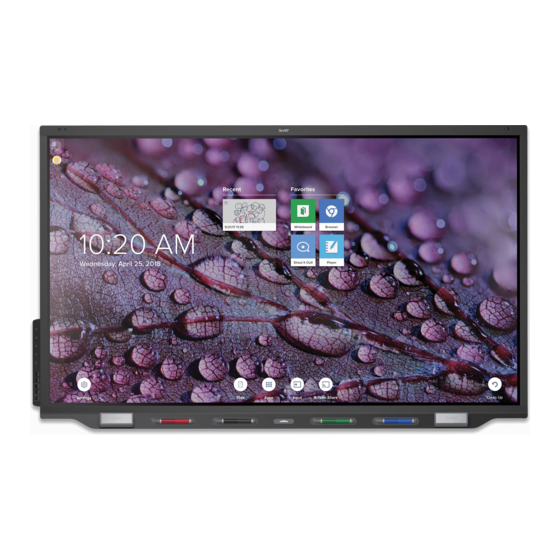
(see More information on page 9). About the display The SMART Board 7000R or 7000R Pro series interactive display is a powerful but easy-to-use collaboration tool that you can use to achieve better outcomes. The display includes an extensive set of features and components. -
Page 15: Writing, Drawing, And Erasing
CHAPTER 1 WELCOME The display’s HyPr Touch™ with EMR technology provides industry-leading touch and digital ink performance, resulting in virtually no lag and zero contact detect height. In addition, its Silktouch™ ultra-smooth finish allows you to use the display for hours without finger burn. Writing, drawing, and erasing The display comes with black, red, blue, and green pens, which you can use to write or draw on the screen. -
Page 16: Audio
For more information, see Chapter 3: Connecting computers and other devices on page 23. Accessory slot You can install an OPS-compatible device, such as a SMART OPS PC module, in the accessory slot. The PCM8 series of SMART OPS PC modules provides a complete Windows 10 Pro solution. -
Page 17: Convenience Panel
CHAPTER 1 WELCOME For more information about the PCM8 series of SMART OPS PC modules, see SMART OPS PC module on page 8. CAUTION The accessory slot’s maximum available power is 60 W. The slot is not a limited power source. To reduce the risk of fire, make sure that accessories connecting to the slot satisfy the fire enclosure requirements of IEC 60950-1 and/or IEC 62368-1. -
Page 18: Ambient Light Sensor
CHAPTER 1 WELCOME If the room is empty for 60 minutes, the display returns to Standby mode. NOTE The sensors can detect people through glass. Consider this when finding a location for the display (see Choosing a location on page 14). Don’t position the display so that the sensors are facing a window. -
Page 19: Identifying Your Specific Model
CHAPTER 1 WELCOME Identifying your specific model SMART offers different models of the SMART Board 7000R and 7000R Pro series interactive display: Model Frame style Screen size (approximate) SBID-7275R White 75" SBID-7286R White 86" SBID-7275R-P Black 75" SBID-7275R-PW White 75" SBID-7286R-P Black 86"... -
Page 20: Smart Ops Pc Module
Stands If you want to move the display from place to place, you can install it on a SMART mobile stand. Alternatively, if you are installing the display on a wall that cannot support the display’s full weight, you can install the display on a SMART floor stand. -
Page 21: More Information
WELCOME More information In addition to this guide, SMART provides other documents for the display in the Support section of the SMART website (smarttech.com/support). Scan the QR code on the cover of this guide to view links to SMART Board 7000R and 7000R Pro series interactive display documents and other support resources. -
Page 23: Chapter 2: Installing The Display
Connecting power and turning on the display for the first time Pairing pens with the display SMART recommends that only trained installers install the display. This chapter is for installers. Installers should read this information along with the installation instructions included with the display before they begin the installation. -
Page 24: Using Transportation Aides
CHAPTER 2 INSTALLING THE DISPLAY IMPORTANT Move the display at your own risk. SMART cannot accept liability for damages or injury that occur during the display’s transportation. When moving the display Follow local safety regulations and standards. Keep the display in its original packaging, including the pallet. -
Page 25: Installing The Display On A Wall
If the display’s glass is cracked or chipped, have it professionally inspected and repaired at a SMART authorized repair center. If the display’s glass shatters, carefully clean up the area and have the display repaired or replaced. -
Page 26: Choosing A Location
CHAPTER 2 INSTALLING THE DISPLAY Choosing a location A display is typically installed at the room’s focal point, such as at the front of a classroom or meeting space. Selecting an appropriate location for the display is crucial for ensuring the best possible experience with the product. - Page 27 INSTALLING THE DISPLAY Factor Considerations Visibility The display’s screen is clearly visible to all users in the room. SMART recommends users sit within a 178° viewing area: NOTE The viewing area depends on the display’s resolution and a variety of other factors.
-
Page 28: Choosing A Height
Be sure the wall you’re installing the display on can support the weight of the display and mounting equipment. If the wall can’t support the weight of the display and mounting equipment, consider using a SMART wall stand to transfer some of the weight from the wall to the floor (see smarttech.com/accessories). -
Page 29: Mounting The Display
The display comes with a WM-SBID-200 wall mount. SMART recommends using this wall mount to install the display on a wall. If you choose a third-party option rather than one of SMART’s mounting options, be sure the wall mount can accommodate the display’s dimensions and support the display’s weight as well as the weight of any attached accessories. -
Page 30: Installing The Display On A Stand
Using SMART mobile stands SMART mobile stands are designed for SMART interactive displays. They are height-adjustable. Some models include integrated speakers, a locking cabinet to secure equipment, and casters that swivel and lock for easy movement. -
Page 31: Connecting Power And Turning On The Display For The First Time
Power Save mode.) You’ll also need to work with your organization’s network administrators to configure the network for the display, see Connecting a SMART display with the iQ experience to a network. Connecting power and turning on the display for the first time The final step in installing and configuring the display is to connect power and turn it on. - Page 32 The display needs an internet connection for downloading and installing important updates. Ask the network administrator to confirm that the network has been correctly configured for the iQ experience. For more information about network configuration, see Connecting a SMART display with the iQ experience to a network. smarttech.com/kb/171538...
-
Page 33: Pairing Pens With The Display
SMART Board 7000R and 7000R Pro series interactive displays (see smarttech.com/kb/171230). If you previously paired a pen with a SMART Board 7000R or 7000R Pro series interactive display, you must pair it with another display to use it with that display. -
Page 35: Chapter 3: Connecting Computers And Other Devices
Viewing a connected computer’s input Setting a connected computer’s resolution and refresh rate Using recommended cables Sharing USB Type-B receptacles Connecting a SMART OPS PC module Viewing the OPS PC module input Connecting external displays Connecting other devices Connecting USB drives, peripherals, and other devices... -
Page 36: Installing Smart Software
Assure supporting, controlling, and securing the warranty term display and your other devices You can purchase additional licenses or subscriptions to SMART software to install on other computers. Contact your authorized SMART reseller (smarttech.com/where) for information about purchasing SMART software. -
Page 37: Connecting Room Computers And Guest Laptops
NOTES Install SMART software on any computers you connect to the display (see Installing SMART software on the previous page). As shown below, HDMI 1 and HDMI 2 share the Touch 1 USB Type-B receptacle, and HDMI 3 and VGA share the Touch 2 USB Type-B receptacle (see Sharing USB Type-B receptacles on page 31). - Page 38 CHAPTER 3 CONNECTING COMPUTERS AND OTHER DEVICES HDMI 1 Connector Standard Connection type Cable HDMI 1 HDMI 2.0 Video/audio HDMI Touch 1 (USB Type-B) Up to USB 3.0 Touch USB 2.0/USB 3.0 HDMI 2 Connector Standard Connection type Cable HDMI 2 HDMI 2.0 Video/audio HDMI Touch 1 (USB Type-B) Up to USB 3.0 Touch USB 2.0/USB 3.0...
- Page 39 CHAPTER 3 CONNECTING COMPUTERS AND OTHER DEVICES HDMI 3 Connector Standard Connection type Cable HDMI 3 HDMI 2.0 Video/audio HDMI Touch 2 (USB Type-B) Up to USB 3.0 Touch USB 2.0/USB 3.0 HDMI 4 Connector Standard Connection type Cable HDMI 4 HDMI 2.0 Video/audio HDMI Convenience panel Up to USB 3.0 Touch USB 2.0/USB 3.0...
-
Page 40: Viewing A Connected Computer's Input
CHAPTER 3 CONNECTING COMPUTERS AND OTHER DEVICES Connector Standard Connection type Cable Video Audio In (Stereo 3.5 mm) Stereo 3.5 mm Audio Stereo 3.5 mm Touch 2 (USB Type-B) Up to USB 3.0 Touch USB 2.0/USB 3.0 Viewing a connected computer’s input Use the Input app to view a connected computer’s input on the display. smarttech.com/kb/171538... -
Page 41: Setting A Connected Computer's Resolution And Refresh Rate
CHAPTER 3 CONNECTING COMPUTERS AND OTHER DEVICES To view a connected computer’s input 1. Connect the computer to the display. 2. Do one of the following: If iQ is enabled If iQ is disabled Tap the Home button below the Tap the Home button below the screen. -
Page 42: Using Recommended Cables
CHAPTER 3 CONNECTING COMPUTERS AND OTHER DEVICES Using recommended cables SMART recommends the following varieties of cable: Cable type Maximum length Recommendation HDMI 23' (7 m) Use only certified HDMI cables that have been tested to support the performance standard you require. -
Page 43: Connecting A Smart Ops Pc Module
Connecting a SMART OPS PC module If your organization has purchased a SMART OPS PC module, you or your organization’s installers can install the OPS PC module in the accessory slot of the SMART Board 7000R or 7000R Pro series interactive display following the OPS PC module’s installation... -
Page 44: Connecting Other Devices
CHAPTER 3 CONNECTING COMPUTERS AND OTHER DEVICES You can install the SMART software that is included with the display on the OPS PC module. For more information about installing software, see Installing SMART software on page 24. Viewing the OPS PC module input To view the OPS PC module input 1. -
Page 45: Connecting Usb Drives, Peripherals, And Other Devices
3.0 Type-A receptacles on the connector panel. You can connect USB drives, peripherals (such as keyboards), and other devices to these connectors and use the devices with the iQ experience, connected computers, and devices installed in the accessory slot (such as the SMART OPS PC module). -
Page 46: Connecting An External Display
CHAPTER 3 CONNECTING COMPUTERS AND OTHER DEVICES NOTE If a SMART OPS PC module is installed in the accessory slot, you can connect USB drives, peripherals, and other devices to the USB 2.0 Type-A, USB 3.0 Type-B, and USB Type-C receptacles on the OPS PC module to access those devices from the OPS PC module input. -
Page 47: Connecting An External Audio System
CHAPTER 3 CONNECTING COMPUTERS AND OTHER DEVICES If a SMART OPS PC module is installed in the accessory slot, you can connect an external display to the HDMI 1.4 out connector on the OPS PC module rather than the one on the display. -
Page 48: Connecting Room Control Systems
CHAPTER 3 CONNECTING COMPUTERS AND OTHER DEVICES In addition to the stereo 3.5 mm out connector, the display provides a Sony/Philips Digital Interface (S/PDIF) out connector (pictured). S/PDIF is a digital audio transmission medium. You need an audio receiver that supports S/PDIF to decode this connection to analog for use with an external sound bar or other... -
Page 49: Connector Diagrams
CHAPTER 3 CONNECTING COMPUTERS AND OTHER DEVICES Connector diagrams Connector panel The following diagram and table present the connectors on the display’s connector panel: Connector Connects to Notes HDMI 2.0 out External display See page 34 and HDMI cables connectors. USB 3.0 Type-A (×3) Supported USB drives, See Connecting USB drives, peripherals, and other... - Page 50 CHAPTER 3 CONNECTING COMPUTERS AND OTHER DEVICES Connector Connects to Notes HDMI 2.0 in HDMI 2 input Use this video and audio input (video and audio) with the Touch 1 input. See page 25 and HDMI cables connectors. HDMI 2.0 in HDMI 3 input Use this video and audio input (video and audio) with the Touch 2 input.
-
Page 51: Convenience Panel
CHAPTER 3 CONNECTING COMPUTERS AND OTHER DEVICES Convenience panel The following diagram and table present the connectors on the display’s convenience panel: Connector Connects to Notes USB 3.0 Type-A (×2) Supported USB drives, See Connecting USB drives, peripherals, and other peripherals, and other devices devices on page 33 and... -
Page 52: Smart Ops Pc Module (Optional)
CHAPTER 3 CONNECTING COMPUTERS AND OTHER DEVICES SMART OPS PC module (optional) The following diagram and table present the connectors on the optional SMART OPS PC module: Connector Connects to Notes USB Type-C Supported USB drives, See Connecting USB drives, peripherals, and other... - Page 53 CHAPTER 3 CONNECTING COMPUTERS AND OTHER DEVICES Connector Connects to Notes Stereo 3.5 mm out External speakers or [N/A] headphones Stereo 3.5 mm in Microphone [N/A] smarttech.com/kb/171538...
-
Page 55: Chapter 4: Maintaining The Display
Turning off, turning on, and resetting the display In most situations, you can put the display to sleep when not using it following the instructions in the SMART Board 7000R and 7000R Pro series interactive displays user guide (smarttech.com/kb/171539). In some situations, such as when you transport the display or clean its screen, you need to turn off the display for a period of time. -
Page 56: Cleaning And Maintaining Hardware
CHAPTER 4 MAINTAINING THE DISPLAY 3. Flick the switch beside the AC power inlet to the OFF (O) position. NOTE Wait at least 30 seconds before turning the display back on. To turn the display back on 1. Flick the switch beside the AC power inlet to the ON (I) position. 2. -
Page 57: Cleaning The Screen
CHAPTER 4 MAINTAINING THE DISPLAY Cleaning the screen Follow these instructions to clean the screen without damaging its anti-glare coating or other product components. CAUTION Do not use permanent or dry-erase markers on the screen. If dry-erase markers are used on the screen, remove the ink as soon as possible with a lint-free, non-abrasive cloth. -
Page 58: Replacing The Pens And Erasers
If condensation appears under the screen after you turn on the display, select an active video source and leave the display on for 48 hours. If the condensation doesn’t dissipate, contact SMART Support if the display is still under warranty. -
Page 59: Updating System Software
CHAPTER 4 MAINTAINING THE DISPLAY IMPORTANT Follow any documentation included with the third-party mounting hardware. To remove the display 1. Turn off any connected computers. 2. Turn off the display (see Turning off, turning on, and resetting the display on page 43). 3. -
Page 60: Applying An Automatic System Software Update Manually
CHAPTER 4 MAINTAINING THE DISPLAY NOTE You can configure your organization’s network to allow or prevent automatic system software and firmware updates (see Connecting to a network). Applying an automatic system software update manually If the display has downloaded but not yet applied the system software, you can start the update process manually from Settings. -
Page 61: Chapter 5: Troubleshooting
The SMART OPS PC module isn’t working as expected Contacting your reseller for additional support This chapter explains how to resolve a variety of common issues with the display and SMART OPS PC module (if installed). If the symptoms you’re encountering aren’t covered below or the solutions to the symptoms don’t work, refer to the SMART knowledge base for additional troubleshooting... -
Page 62: The Display Is Turning On When It Shouldn't
CHAPTER 5 TROUBLESHOOTING Symptom Troubleshooting steps The power light is lit, but the screen Make sure nothing is blocking the proximity sensors so that they can detect is blank. people in the room and either turn on the display or place the display in Ready mode. - Page 63 Home screen. If it appears correctly, the issue is with the video input. Take a photograph of the screen and send it to SMART support. If SMART support determines that the issue is with the screen and the display is under warranty, you may be eligible for a replacement.
-
Page 64: There's No Sound Or There's A Problem With The Sound
CHAPTER 5 TROUBLESHOOTING There’s no sound or there’s a problem with the sound Symptom Troubleshooting steps There’s no sound. If you’re using an external audio system, make sure it is turned on. Make sure the cables connecting the display to the computer are securely fastened. -
Page 65: Touch Isn't Working As Expected
On Mac computers, open System Information and make sure there are no error messages in the display’s row. For Mac computers with macOS Mojave, see How to resolve issues with installing and using SMART Learning Suite software on macOS Mojave. The display responds to touch Restart the display. -
Page 66: Iq Apps Aren't Working As Expected
You’re experiencing other issues Use only SMART Board 7000R or 7000R Pro series interactive display pens with with the pens. the display. Pens from other interactive displays aren’t compatible. Return the pen to its magnetic holder to calibrate it. -
Page 67: The Smart Ops Pc Module Isn't Working As Expected
Press and hold the power button on the OPS PC module. b. Wait two minutes. c. Press the power button to turn on the OPS PC module. If restarting the OPS PC module doesn’t resolve the issue, contact SMART support. There is an issue with Bluetooth. - Page 68 (pictured). TIPS Scan the QR code on the label to view the SMART Board 7000R or 7000R Pro series interactive display support pages on the SMART website. You can also find the serial number in the iQ settings (see Serial Number on page 64).
-
Page 69: Appendix A: Adjusting Iq Settings
See the settings for more information. Some settings aren’t available while you’re signed in to your SMART account. Sign out of your SMART account on your display to see all settings. - Page 70 [N/A] Shows information about the [N/A] System Bluetooth display’s Bluetooth SMART Cloud [Status] Shows the status of SMART Cloud [N/A] System SMART Cloud Status Service Region [N/A] Shows the service region [N/A] System Personalization NOTE If iQ is disabled, Personalization settings are not available.
- Page 71 Indefinitely Mobile App Enables or disables the Capture If this option is off, the User Saving Whiteboards function in the SMART kapp app QR code is not visible. The SMART kapp app is unable to connect to the display and your mobile device is...
- Page 72 Cast protocol. enabled by default. Enables or disables the Miracast Miracast is enabled System Miracast protocol. by default. SMART Support may ask users Performance System Performance Logging to enable Performance Logging Logging is disabled to help diagnose issues. by default.
- Page 73 System settings Option Values Function Notes User or system setting System Enables or disables the iQ [N/A] System SMART Board with iQ experience Display Screen Adjustment 0–100 Sets the overall brightness of the [N/A] System Brightness image 0–100 Sets the difference in brightness...
- Page 74 APPENDIX A ADJUSTING IQ SETTINGS Option Values Function Notes User or system setting 0–100 Sets the audio output from the Drag the slider System Balance speakers all the way to the left to have all audio from the left speaker. Drag the slider all the way to the right to have...
- Page 75 Copy diagnostic logs to a USB drive [N/A] [N/A] Save Log File Sends usage statistics and error [N/A] User Improve the reports to SMART Experience [Support ID] Shows the support ID associated [N/A] [N/A] Support ID with the display Security [N/A] Lock down the display’s settings...
- Page 76 About [N/A] Select a name for your display [N/A] System Board Name [N/A] Shows the SMART support site [N/A] [N/A] Help Send Feedback [N/A] Send feature request to SMART [N/A] [N/A] [N/A]...
- Page 77 Shows the display’s scaler version [N/A] [N/A] Scaler version [N/A] [N/A] [N/A] [N/A] Legal Information End User License [N/A] Shows the SMART end user license [N/A] [N/A] agreement Agreement [N/A] Shows the open source licenses [N/A] [N/A] Open Source Licenses [N/A]...
-
Page 79: Appendix B: Managing The Display Using Rs-232
Appendix B Managing the display using RS-232 Configuring the computer’s serial interface settings Power states Commands and responses Power state commands Input commands Brightness commands Freeze commands Screen shade commands Volume commands Mute commands Firmware version commands Serial number commands Part number commands Asynchronous state reporting commands Factory reset commands... -
Page 80: Configuring The Computer's Serial Interface Settings
SMART also offers SMART Remote Management cloud-based device-management software, which you can use to manage SMART Board interactive displays with iQ and devices running Windows, Chrome™ OS, Android™, and iOS operating systems. For more information, see SMART Remote Management. -
Page 81: Power States
APPENDIX B MANAGING THE DISPLAY USING RS-232 Power states The display has six power states: Power state Description The display is in normal operating mode. READY The screen is off, but the display is ready to turn on when the following occurs: A user presses the Power button on the convenience panel or the... - Page 82 APPENDIX B MANAGING THE DISPLAY USING RS-232 In the example below, the user used =-50 instead of -50. INCORRECT >set volume=-50 invalid cmd: setvolume=-50 > NOTES Use ASCII formatted commands. Commands aren’t case-sensitive and extra spacing is ignored. You can use the BACKSPACE key when typing commands. Review each entry carefully before you press ENTER.
-
Page 83: Power State Commands
APPENDIX B MANAGING THE DISPLAY USING RS-232 To increase or decrease the value of a setting Use the set command to increase or decrease the value by a designated number. This example increases the volume by 5: >set volume+5 volume=70 >... -
Page 84: Input Commands
APPENDIX B MANAGING THE DISPLAY USING RS-232 Input commands Get command Set command Response get input set input[Value] input=[Value] Where [Value] is one of the following: Where [Value] is one of the following: =hdmi1 hdmi1 =hdmi2 hdmi2 =hdmi3 hdmi3 =hdmi4 hdmi4 =vga1 vga1... -
Page 85: Screen Shade Commands
APPENDIX B MANAGING THE DISPLAY USING RS-232 Screen shade commands Get command Set command Response get screenshade set screenshade[Value] screenshade=[Value] Where [Value] is one of the following: Where [Value] is one of the following: =off Volume commands Get command Set command Response get volume set volume[Value]... -
Page 86: Serial Number Commands
APPENDIX B MANAGING THE DISPLAY USING RS-232 Serial number commands Get command Response get serialnum serialnum=[Value] Where [Value] is the serial number. Part number commands Get command Response get partnum partnum=[Value] Where [Value] is the part number, including the revision. Asynchronous state reporting commands Get command Set command... -
Page 87: Resolving Issues With Managing The Display Using Rs-232
APPENDIX B MANAGING THE DISPLAY USING RS-232 Resolving issues with managing the display using RS-232 The following table presents common issues with managing the display using RS-232 and explains how to resolve them: Symptom Troubleshooting steps Managing the display using RS-232 Make sure all the cable connections are secure. -
Page 89: Appendix C: Hardware Environmental Compliance
Appendix C Hardware environmental compliance SMART Technologies supports global efforts to ensure that electronic equipment is manufactured, sold and disposed of in a safe and environmentally friendly manner. Waste Electrical and Electronic Equipment (WEEE) Electrical and electronic equipment and batteries contain substances that can be harmful to the environment and to human health. - Page 90 SMART TECHNOLOGIES smarttech.com/support smarttech.com/contactsupport smarttech.com/kb/171538...
Need help?
Do you have a question about the SMART Board 7000R Series and is the answer not in the manual?
Questions and answers