SMART Board 6000S Series Installation And Maintenance Manual
Hide thumbs
Also See for SMART Board 6000S Series:
- Quick start manual (8 pages) ,
- Basic classroom troubleshooting (3 pages) ,
- User manual (62 pages)
Table of Contents
Advertisement
6000S
Installation and maintenance guide
SBID-6265S-V3
|
SBID-6275S-V3
SBID-6065S-V3
|
SBID-6075S-V3
SBID-6265S-C
|
SBID-6275S-C
SBID-6065S-C
|
SBID-6075S-C
SBID-6265S
|
SBID-6065S
|
Was this document helpful?
smarttech.com/docfeedback/171414
SMART Board
|
6000S Pro
series interactive displays
|
SBID-6286S-V3
|
SBID-6265S-V3-PW
SBID-6265S-V3-P
|
SBID-6275S-V3-P
|
SBID-6086S-V3
|
SBID-6065S-V3-PW
SBID-6065S-V3-P
|
SBID-6075S-V3-P
SBID-6465S-V3-P
|
SBID-6475S-V3-P
|
SBID-6286S-C
|
SBID-6265S-CPW
|
SBID-6086S-C
|
SBID-6065S-CPW
SBID-6275S
|
SBID-6286S
|
SBID-6265S-PW
SBID-6075S
|
SBID-6086S
|
SBID-6065S-PW
IDS665-3
|
IDS675-3
IDS665-1
|
IDS675-1
®
|
SBID-6275S-V3-PW
|
|
SBID-6286S-V3-P
|
SBID-6075S-V3-PW
|
|
SBID-6086S-V3-P
|
SBID-6486S-V3-P
|
SBID-6275S-CPW
|
SBID-6286S-CPW
|
SBID-6075S-CPW
|
SBID-6086S-CPW
|
SBID-6275S-PW
|
SBID-6286S-PW
|
SBID-6075S-PW
|
SBID-6086S-PW
|
IDS686-3
|
IDS686-1
SBID-6286S-V3-PW
SBID-6086S-V3-PW
Advertisement
Chapters
Table of Contents

Related Manuals for SMART SMART Board 6000S Series


Summary of Contents for SMART SMART Board 6000S Series
- Page 1 SMART Board ® 6000S 6000S Pro series interactive displays Installation and maintenance guide SBID-6265S-V3 SBID-6275S-V3 SBID-6286S-V3 SBID-6265S-V3-PW SBID-6275S-V3-PW SBID-6286S-V3-PW SBID-6265S-V3-P SBID-6275S-V3-P SBID-6286S-V3-P SBID-6065S-V3 SBID-6075S-V3 SBID-6086S-V3 SBID-6065S-V3-PW SBID-6075S-V3-PW SBID-6086S-V3-PW SBID-6065S-V3-P SBID-6075S-V3-P SBID-6086S-V3-P SBID-6465S-V3-P SBID-6475S-V3-P SBID-6486S-V3-P SBID-6265S-C SBID-6275S-C SBID-6286S-C SBID-6265S-CPW SBID-6275S-CPW SBID-6286S-CPW...
- Page 2 © 2022 SMART Technologies ULC. All rights reserved. No part of this publication may be reproduced, transmitted, transcribed, stored in a retrieval system or translated into any language in any form by any means without the prior written consent of SMART Technologies ULC. Information in this manual is subject to change without notice and does not represent a commitment on the part of SMART.
-
Page 3: Important Information
If the display requires replacement parts, make sure the service technician uses replacement parts specified by SMART Technologies or parts with the same characteristics as the original. Ensure that any cables that cross the floor to the display are properly bundled and marked to avoid a trip hazard. - Page 4 Contents Disconnect the display’s power cable from the wall outlet and seek assistance from qualified service personnel if any of the following occur: The power cable or plug is damaged Liquid is spilled into the display Objects fall into the display ...
- Page 5 Contents Important The following table shows the typical operating power for the display: Models Regulatory Typical power Models 6000S (V3) SBID-6X65S-V3, SBID-6X65S-V3-PW, SBID- IDS665-3 100V to 240V AC, 50 Hz to 60 Hz, 6X65S-V3-P, 105 W SBID-6X75S-V3, SBID-6X75S-V3-PW, SBID- IDS665-3 100V to 240V AC, 50 Hz to 60 Hz, 6X75S-V3-P,...
-
Page 6: Table Of Contents
There’s no sound or there’s a problem with the sound Touch isn’t working as expected The pens and erasers aren’t working as expected iQ apps aren’t working as expected SMART software on connected computers isn’t working as expected The SMART OPS PC module isn’t working as expected smarttech.com/kb/171414... - Page 7 Serial number commands Part number commands Model number commands Resolving issues with managing the display using RS-232 Appendix D Managing SMART Board 6000S (C) or 6000S series displays using RS-232 Connecting multiple displays Configuring the computer’s serial interface settings Commands and responses...
-
Page 8: Chapter 1 Welcome
Accessory mounting points Identifying your specific model Accessories Pen accessory kit Tool Explorer-enabled objects and manipulatives SMART OPS PC module Stands USB extenders More information ® This chapter introduces the SMART Board 6000S and 6000S Pro series interactive displays. smarttech.com/kb/171414... -
Page 9: About This Guide
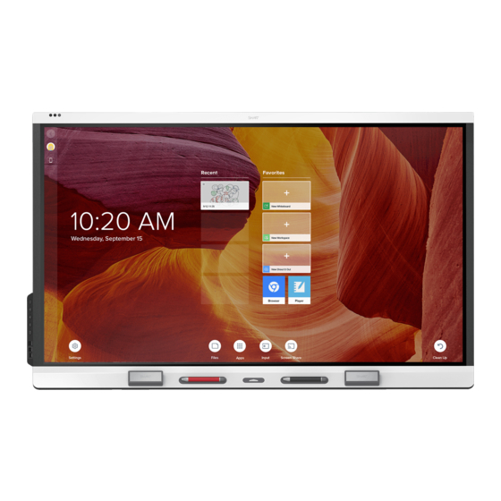
(see More information on page 19). About the display The SMART Board 6000S or 6000S Pro series interactive display with iQ is the hub of your classroom or meeting room. - Page 10 Chapter 1 Welcome Touch You can do everything on the display that you can do at your computer—open and close applications, meet with others, create new documents or edit existing ones, visit websites, play and manipulate videos, and so on—by touching the display’s surface. You can use an array of gestures within applications, including panning, scaling, rotating and zooming in and out.
- Page 11 For more information about using Tool Explorer-enabled objects on the display, see the SMART Board 6000S and 6000S Pro series interactive displays user guide (smarttech.com/kb/171415).
- Page 12 You can connect room computers and guest laptops to the display and view and interact with their inputs. The display comes with SMART software that you can install on connected computers to take full advantage of the display’s features while using the connected computers.
- Page 13 Chapter 1 Welcome Accessory slot You can install an OPS-compatible device, such as a SMART OPS PC module, in the accessory slot. ® SMART OPS PC modules provide a complete Windows 10 Pro installation. For more information on SMART OPS PC modules, see SMART OPS PC module on page 19.
- Page 14 For more information on energy saving modes, see About energy saving modes on page 30. The proximity sensor on the SMART Board 6000S (V3) models responds when the display is in the networked standby and the standby power states. On the 6000S and 6000S (C) models, the proximity sensor responds only when the display is in the networked standby power state.
- Page 15 The display allows you to sign in to your SMART Account using NFC (near field communication): just tap your SMART ID card on the screen and enter a PIN. This feature helps you save time signing in to your account without typing your username and password.
-
Page 16: Identifying Your Specific Model
The display features M4 mounting points located at the top-left and top-right for SMART approved accessories. Identifying your specific model SMART offers a variety of models of the SMART Board 6000S and 6000S Pro series interactive display: Model/SKUs Frame style... - Page 17 Chapter 1 Welcome Model/SKUs Frame style Screen size iQ embedded Microphone array (approximate) computing 6000S (C) SBID-6265S-C White 65" SBID-6275S-C White 75" SBID-6286S-C White 86" SBID-6065S-C White 65" SBID-6075S-C White 75" SBID-6086S-C White 86" 6000S (C) Pro SBID-6265S-CPW White 65"...
-
Page 18: Accessories
Note Support for the different pens, objects, and manipulatives varies depending on the model of display. See the SMART Board 6000S and 6000S Pro user guide (smarttech.com/kb/171415) smarttech.com/kb/171414... -
Page 19: More Information
Stands If you want to move the display from place to place, you can install it on a SMART mobile stand. If you are installing the display on a wall that cannot support the display’s full weight, you can install the display on a SMART floor stand. -
Page 20: Chapter 2 Installing The Display
Connecting power and turning on the display for the first time About energy saving modes SMART recommends that only trained installers install the display. This chapter is for installers. Installers should read this information along with the installation instructions included with the display before they begin the installation. -
Page 21: Using Transportation Aides
Chapter 2 Installing the display Important Move the display at your own risk. SMART cannot accept liability for damages or injury that occur during the display’s transportation. When moving the display: Follow local safety regulations and standards. -
Page 22: Installing The Display On A Wall
If the display’s glass is cracked or chipped, have it professionally inspected and repaired at a SMART authorized repair center. If the display’s glass shatters, carefully clean up the area and have the display repaired or replaced. -
Page 23: Choosing A Location
Chapter 2 Installing the display Choosing a location A display is typically installed at the room’s focal point, such as at the front of a classroom or meeting space. Selecting an appropriate location for the display is crucial for ensuring the best possible experience with the product. - Page 24 There is adequate ventilation or air conditioning around the display so that heat can flow away from it and the mounting equipment. SMART recommends at least 2" (5 cm) of space on all sides of the display for proper airflow.
-
Page 25: Choosing A Height
Be sure the wall you’re installing the display on can support the weight of the display and mounting equipment. If it can’t, consider using a SMART wall stand to transfer some of the weight from the wall to the floor (see smarttech.com/accessories). -
Page 26: Mounting The Display
If you choose a third-party option rather than one of SMART’s mounting options, be sure the wall mount can accommodate the display’s dimensions and support the display’s weight as well as the weight of any attached accessories. -
Page 27: Installing The Display On A Stand
For more information about SMART mobile stands, see smarttech.com/accessories. Using a third-party stand For information on selecting and using a third-party stand, see Installing your SMART Board 6000S on a stand. smarttech.com/kb/171414... -
Page 28: Connecting To A Network
Standby is enabled in Settings but not when Standby is enabled in Settings. SMART Board 6000S (V3) SMART Board 6000S and 6000S (C) For more information about the display’s network connection and configuration, see Connecting a SMART display with the iQ experience to a network. smarttech.com/kb/171414... -
Page 29: Connecting Power And Turning On The Display For The First Time
Chapter 2 Installing the display Connecting power and turning on the display for the first time The final step in installing and configuring the display is to connect power and turn it on. When you first turn on the display, a setup wizard appears. Follow the steps in the wizard to complete the setup. To connect the display to power ... -
Page 30: About Energy Saving Modes
The display needs an internet connection for downloading and installing important updates. Ask the network administrator to confirm that the network has been correctly configured for the iQ experience. For more information about network configuration, see Connecting a SMART display with the iQ experience to a network. -
Page 31: Chapter 3 Connecting Computers And Other Devices
Connecting room control systems Connector diagrams SMART Board 6000S (V3) connector panel SMART Board 6000S (C) and 6000S connector panel Convenience panel Warning Ensure that any cables that cross the floor to the display are properly bundled and marked to avoid a trip hazard. - Page 32 Tip You can purchase additional licenses or subscriptions to SMART software to install on other computers. Contact your authorized SMART reseller (smarttech.com/where) for information about purchasing SMART software.
-
Page 33: Connecting Room Computers And Guest Laptops
You can then run the cables across floors or behind walls as needed. Connector panel Convenience panel SMART Board 6000S (C) and 6000S (V3) SMART Board 6000S (V3) SMART Board 6000S SMART Board 6000S and 6000S (C) - Page 34 Chapter 3 Connecting computers and other devices Note Install SMART software on computers you connect to the display (see Installing SMART software on page 31). You can charge devices connected to the USB Type-C receptacles. SMART Board 6000S (V3) models can provide up to 65 W to connected devices (the USB Type-C receptacle labeled USB-C 2 on the rear connector panel provides 30 W when an OPS PC module is installed).
- Page 35 If you have problems with such a cable or an extender of any type, test the connection with a shorter cable before contacting SMART Support. The performance of cables longer than 23' (7 m) is highly dependent on the cable’s quality.
-
Page 36: Connecting A Smart Ops Pc Module
For troubleshooting information for connected computers, see Chapter 5 Troubleshooting on page 51. Connecting a SMART OPS PC module If your organization has purchased a SMART OPS PC module, you or your organization’s installers can install the OPS PC module in the display’s accessory slot following the OPS PC module’s installation instructions... - Page 37 A receptacle on the convenience panel, or two USB 3.0 Type-A receptacles on the convenience panel (see images below). The SMART Board 6000S (V3) models also include a USB Type-C receptacle on the connector panel. All models include one USB 3.0 Type-A receptacle on the connector panel.
- Page 38 Chapter 3 Connecting computers and other devices SMART Board 6000S and 6000S (C) SMART Board 6000S (V3) Important If the connected external display doesn’t support HDCP, the image on the external display is limited to 480p resolution. For full resolution output, connect a display that supports HDCP.
- Page 39 You can use the display’s RS-232 connector to connect a third-party external control system to the display (see Appendix D Managing SMART Board 6000S (C) or 6000S series displays using RS-232 on page 82 or Appendix C Managing the SMART Board 6000S (V3) display using RS-232 on page 74). Note ...
-
Page 40: Connector Diagrams
Chapter 3 Connecting computers and other devices Connector diagrams SMART Board 6000S (V3) connector panel The following diagram and table present the connectors on the display’s connector panel: Side Bottom Connector Connects to Notes USB Type-C USB-C 2 input See page ... - Page 41 See page 38 and Analog audio cables and connectors. RS-232 Room control system See Appendix C Managing the SMART Board 6000S (V3) display using RS-232 on page 74 and RS- 232 cables and connectors. Stereo 3.5 mm in VGA input (audio) See page ...
- Page 42 Chapter 3 Connecting computers and other devices SMART Board 6000S (C) and 6000S connector panel The following diagram and table present the connectors on the display’s connector panel: Side Bottom Connector Connects to Notes HDMI 2.0 out External display See Connecting an external display on page ...
- Page 43 37 and USB cables and connectors. SMART Board 6000S (C) and 6000S (V3) models feature one USB 3.0 Type-A connector. All other models feature two USB 3.0 Type-A connectors. smarttech.com/kb/171414...
- Page 44 See page 33 and USB cables and connectors. HDMI 2.0 in HDMI 3 input See page 33 and HDMI cables and (video and audio) connectors. USB Type-C USB-C See page 33 and HDMI cables and connectors. SMART Board 6000S (C) and 6000S (V3) models. smarttech.com/kb/171414...
-
Page 45: Chapter 4 Maintaining The Display
Turning off, turning on, and resetting the display In most situations, you can put the display in an energy saving mode when not using it following the instructions in the SMART Board 6000S and 6000S Pro series interactive displays user guide (smarttech.com/kb/171415). -
Page 46: Cleaning And Maintaining Hardware
Chapter 4 Maintaining the display 3. Flick the switch beside the AC power inlet to the OFF (O) position. Note Wait at least 30 seconds before turning the display back on. To turn the display back on 1. Flick the switch beside the AC power inlet to the ON (I) position. ... -
Page 47: Cleaning The Touch Sensors
Do not clean the screen using cleaning solutions or glass cleaners that are not approved by SMART. Non-approved cleansers can cause deterioration or discoloration of the screen. To clean the screen 1. Turn off the display (see Turning off, turning on, and resetting the display on page 45). -
Page 48: Maintaining Ventilation
If condensation appears under the screen after you turn on the display, select an active video source and leave the display on for 48 hours. If the condensation doesn’t dissipate, contact SMART Support if the display is still under warranty. -
Page 49: Removing And Transporting The Display
Chapter 4 Maintaining the display Note For pen and eraser part numbers, refer to the service parts diagrams. Removing and transporting the display On occasion, you might need to remove the display from its current wall mount and transport it to another location. -
Page 50: Updating System Software
Chapter 4 Maintaining the display To transport the display See Moving the display to the installation site on page 20. Updating system software When an update to the system software or firmware is available, the display downloads the update in the background then waits for four hours of inactivity. -
Page 51: Chapter 5 Troubleshooting
Contacting your reseller for additional support This chapter explains how to resolve a variety of common issues with the display. If your specific issue isn’t described here or the solutions to the symptoms don’t work, refer to the SMART knowledge base for additional troubleshooting information. -
Page 52: The Display Is Turning On When It Shouldn't
Chapter 5 Troubleshooting The display is turning on when it shouldn’t Symptom Troubleshooting steps The display turns on or enters Ready Check for and, if possible, move the display away from the following: mode when it shouldn’t. Direct sunlight ... - Page 53 Home screen. If it appears correctly, the issue is with the video input. Take a photograph of the screen and send it to SMART support. If SMART support determines that the issue is with the screen and the display is under warranty, you may be eligible for a replacement.
-
Page 54: There's No Sound Or There's A Problem With The Sound
The microphone array is not picking If you’re using an external computer, ensure that the computer’s audio settings are up sound, and the green indicator configured to use the SMART IFP Mic as the input source. light is not lit. smarttech.com/kb/171414... -
Page 55: Touch Isn't Working As Expected
See Turning off, turning on, and resetting the display on page 45. Make sure SMART Product Drivers and SMART Ink are installed and running on any When you touch the screen, the connected computers. pointer doesn’t appear in the correct ... -
Page 56: Iq Apps Aren't Working As Expected
Confirm with the installers that the computer is connected to the display with only a Writing is intermittent. single cable. Make sure SMART Product Drivers and SMART Ink are installed and running on any connected computers. Ink disappears as you write. ... -
Page 57: Smart Software On Connected Computers Isn't Working As Expected
The SMART OPS PC module isn’t working as expected Symptom Troubleshooting steps See the SMART OPS PC modules user guide (smarttech.com/kb/171747). The SMART OPS PC module isn’t working as expected. Contacting your reseller for additional support If an issue you’re experiencing with the display persists or isn’t covered in this chapter or the knowledge base, contact your authorized SMART reseller (smarttech.com/where) for support. - Page 58 Chapter 5 Troubleshooting Tips Scan the QR code on the label to view the SMART Board 6000S or 6000S Pro series interactive display support pages on the SMART website. The label features the display’s base model number (for example, SBID-6065-V3). Please note this number is different from the actual model/SKU number (for example SBID-6265-V3).
-
Page 59: Appendix A Adjusting Settings
System-level settings apply to all users. See the settings for more information. Some settings aren’t available while you’re signed in to your SMART Account. Sign out of your SMART Account on the display to see all settings. Network settings... -
Page 60: Personalization
View available bluetooth [N/A] Shows available Bluetooth devices. Turn on System devices Bluetooth to view available Bluetooth devices. SMART Cloud Service Region [N/A] Shows the service region. [N/A] System Personalization Note If iQ is disabled, Personalization settings are not available. Option... -
Page 61: Application Settings
Enables or disables access to See Opening your User integration in Files Google Drive when you’re signed Google Drive or Library in to your SMART Account. OneDrive on the display. Allow OneDrive Enables or disables access to See Opening your User integration in Files OneDrive when you’re signed in... - Page 62 Function Notes User or system setting SMART kapp Mobile App These options are not available for SMART Board 6000S (V3) or MX-V3 models Saving Whiteboards Enables or disables the Capture If this option is off, the User function in the SMART kapp app.
-
Page 63: System Settings
Option Values Function Notes User or system setting Auto-disconnect from When enabled, the display SMART recommends System Wifi for Miracast disconnects from the network enabling this setting for when a device shares its screen areas with high using Miracast. network saturation or busy networks. - Page 64 Appendix A Adjusting settings Option Values Function Notes User or system setting SMART Board with iQ Enables or disables the iQ [N/A] System experience. Default input Inputs available Select the default input the display The iQ System on the display.
- Page 65 Appendix A Adjusting settings Option Values Function Notes User or system setting Go to energy saving Disabled Sets the number of minutes of The default is 60 System mode after inactivity before the display enters minutes. 1 min an energy saving mode. 5 mins 30 mins 1 hour...
- Page 66 Warm Very Warm Lightness 0–488 Sets the overall lightness of the [N/A] System image. This option is not available for SMART Board 6000S (V3) models. Contrast 0–488 Sets the overall contrast of the [N/A] System image. This option is not...
- Page 67 When enabled, show the input [N/A] System when there is no signal previews when there is no signal. Audio Audio In These options are available for SMART Board 6000S (V3) models only. Volume Range slider Sets the microphone’s volume. [N/A] System Built-in microphone Enables or disables the display’s...
- Page 68 Appendix A Adjusting settings Option Values Function Notes User or system setting Balance Range slider Sets the audio output from the Drag the slider System speakers. all the way to the left to have all audio from the left speaker. Drag the slider all the way to the right to have all...
- Page 69 Save Log File to a USB [N/A] Copy diagnostic logs to a USB drive. [N/A] [N/A] Submit Log file to SMART [N/A] Send diagnostic logs to SMART. [N/A] [N/A] Improve the Experience Sends usage statistics and error...
- Page 70 Appendix A Adjusting settings Option Values Function Notes User or system setting Security Lock Down Settings [N/A] Lock down the display’s settings See Locking System using a security certificate on a USB down the drive. Settings app for more information. Make passwords visible Reveals characters when typing a [N/A]...
- Page 71 System Enabled Management on the display. Radix Viso version [N/A] Shows the Radix Viso version. [N/A] System About Board Name [N/A] Select a name for your display. [N/A] System Help [N/A] Shows the SMART support site for [N/A] [N/A] smarttech.com/kb/171414...
- Page 72 Shows the display’s pen detection [N/A] [N/A] system firmware version. Legal Information [N/A] [N/A] [N/A] [N/A] End User License [N/A] Shows the SMART end user license [N/A] [N/A] Agreement agreement. Open Source Licenses [N/A] Shows the open source licenses. [N/A] [N/A] SMART Intellectual...
-
Page 73: Appendix B Enrolling The Display In Smart Remote Management
Appendix B Enrolling the display in SMART Remote Management Your SMART Board 6000S or 6000S Pro series interactive display has a built-in feature that enables you to enroll the display with your organization’s SMART Remote Management account. When you enroll... -
Page 74: Appendix C Managing The Smart Board 6000S (V3) Display Using Rs-232
Appendix C Managing the SMART Board 6000S (V3) display using RS- Configuring the computer’s serial interface settings Commands and responses Power state commands Input commands Brightness commands Freeze commands Screen shade commands Volume commands Mute commands Firmware version commands Serial number commands... -
Page 75: Configuring The Computer's Serial Interface Settings
Use only a standard RS-232 cable. Do not use a null modem cable. Null modem cables typically have ends of the same type. Tip SMART also offers SMART Remote Management cloud-based device-management software, which you can use to manage SMART Board interactive displays with iQ and devices running Windows, ™ ™ Chrome OS, Android , and iOS operating systems. -
Page 76: Commands And Responses
Appendix C Managing the SMART Board 6000S (V3) display using RS-232 Commands and responses To access display information or to adjust display settings using the room control system, type commands after the command prompt (>) and wait for the response from the display. -
Page 77: Power State Commands
Appendix C Managing the SMART Board 6000S (V3) display using RS-232 To assign a value to a setting Use a set command. This example sets the volume to 65: >set volume=65 volume=65 > To increase or decrease the value of a setting ... - Page 78 Appendix C Managing the SMART Board 6000S (V3) display using RS-232 The display has six power states: Power state Description The display is in normal operating mode. READY The screen is off, but the display is ready to turn on when one of the following occurs: ...
-
Page 79: Input Commands
Appendix C Managing the SMART Board 6000S (V3) display using RS-232 With the exception of get powerstate and set powerstate, commands are available only when the display is in READY or ON power state. Input commands Get command Set command... -
Page 80: Screen Shade Commands
Appendix C Managing the SMART Board 6000S (V3) display using RS-232 Screen shade commands Get command Set command Response get screenshade set screenshade[Value] screenshade=[Value] Where [Value] is one of the following: Where [Value] is one of the following: ... -
Page 81: Serial Number Commands
Appendix C Managing the SMART Board 6000S (V3) display using RS-232 Serial number commands Get command Response get serialnum serialnum=[Value] Where [Value] is the serial number. Part number commands Get command Response get partnum partnum=[Value] Where [Value] is the part number, including the revision. -
Page 82: Appendix D Managing Smart Board 6000S (C) Or 6000S Series Displays Using Rs-232
Appendix D Managing SMART Board 6000S (C) or 6000S series displays using RS-232 Connecting multiple displays Configuring the computer’s serial interface settings Commands and responses Power state commands Input commands Brightness commands Freeze commands Screen shade commands Volume commands Mute commands... -
Page 83: Connecting Multiple Displays
Use only a standard RS-232 cable. Do not use a null modem cable. Null modem cables typically have ends of the same type. Tip SMART also offers SMART Remote Management cloud-based device-management software, which you can use to manage SMART Board interactive displays with iQ and devices running Windows, ™ ™ Chrome OS, Android , and iOS operating systems. -
Page 84: Configuring The Computer's Serial Interface Settings
Appendix D Managing SMART Board 6000S (C) or 6000S series displays using RS-232 Configuring the computer’s serial interface settings Configure the computer’s serial interface before sending commands to the display. To configure the computer’s serial interface 1. Turn on the display. - Page 85 Appendix D Managing SMART Board 6000S (C) or 6000S series displays using RS-232 invalid cmd: setvolume=-50 > Notes Use ASCII formatted commands. Commands aren’t case-sensitive and extra spacing is ignored. In many terminal applications on a computer, you can use the BACKSPACE key when typing commands.
- Page 86 Appendix D Managing SMART Board 6000S (C) or 6000S series displays using RS-232 To increase or decrease the value of a setting Use the set command to increase or decrease the value by a designated number. This example increases the volume by 5: >set volume+5...
-
Page 87: Power State Commands
Appendix D Managing SMART Board 6000S (C) or 6000S series displays using RS-232 Power state commands Get command Set command Response get powerstate set powerstate[Value] powerstate=[Value] Where [Value] is one of the following: Where [Value] is one of the following: ... -
Page 88: Input Commands
Appendix D Managing SMART Board 6000S (C) or 6000S series displays using RS-232 Power state Description POWERSAVE The screen is off, and the display is a very low power state. The display enters READY or ON state when one of the following occurs: ... -
Page 89: Brightness Commands
Appendix D Managing SMART Board 6000S (C) or 6000S series displays using RS-232 Get command Set command Response If multiple displays are connected [Display],@ get input [Display],@ set input[Value] @,[Display] input=[Value] Where [Display] is the display’s label Where Where (A, B, and so on). -
Page 90: Screen Shade Commands
Appendix D Managing SMART Board 6000S (C) or 6000S series displays using RS-232 Screen shade commands Get command Set command Response get screenshade set screenshade[Value] screenshade=[Value] Where [Value] is one of the following: Where [Value] is one of the following: ... -
Page 91: Serial Number Commands
Appendix D Managing SMART Board 6000S (C) or 6000S series displays using RS-232 Serial number commands Get command Response get serialnum serialnum=[Value] Where [Value] is the serial number. Note If multiple displays are connected, the response includes the serial numbers for all displays separated by commas. -
Page 92: Certification And Compliance
IDS665-1, IDS675-1, IDS686-1 Innovation, Science and Economic Responsible Party – U.S. Contact Information Development Canada statement SMART Technologies Inc. 2401 4th Ave, 3rd Floor This device complies with RSS-210 of the Innovation, Science Seattle, WA 98121 and Economic Development Canada Rules. Operation is compliance@smarttech.com... - Page 93 Japan VCCI Class A statement – EU Declaration of Conformity applicable only to models certified for Hereby, SMART Technologies ULC declares that the radio sale in Japan equipment type Interactive Display IDS665-3, IDS675-3, IDS686-3, IDS665-1, IDS675-1, IDS686-1 and the OPS AM50, こ...
- Page 94 DEALER No: DA0076339/11 Regulatory models IDS686-1 REGISTERED No: ER81697/20 DEALER No: DA0076339/11 Hardware environmental compliance SMART Technologies supports global efforts to ensure that electronic equipment is manufactured, sold, and disposed of in a safe and environmentally friendly manner. Waste Electrical...
- Page 95 SMART Technologies smarttech.com/support smarttech.com/contactsupport smarttech.com/kb/171414...
Need help?
Do you have a question about the SMART Board 6000S Series and is the answer not in the manual?
Questions and answers