
Related Manuals for Tektronix RMD5000


Summary of Contents for Tektronix RMD5000
- Page 1 RMD5000 Rackmount Kit Instructions www.tektronix.com *P075102000* 075-1020-00...
- Page 2 Copyright © Tektronix. All rights reserved. Licensed software products are owned by Tektronix or its subsidiaries or suppliers, and are protected by national copyright laws and international treaty provisions. Tektronix products are covered by U.S. and foreign patents, issued and pending. Information in this publication supersedes that in all previously published material.
-
Page 3: Service Safety Summary
Use Care When Servicing With Power On. Dangerous voltages or currents may exist in this product. Disconnect power and disconnect test leads before removing protective panels, soldering, or replacing components. To avoid electric shock, do not touch exposed connections. RMD5000 Rackmount Kit Instructions... -
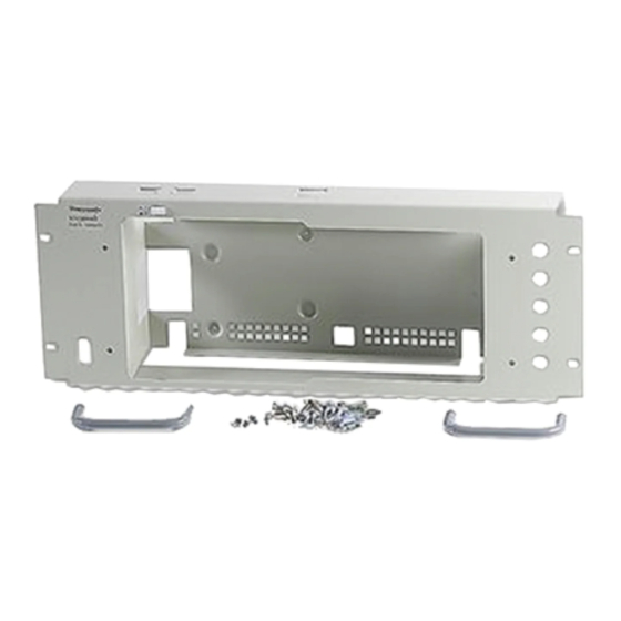
Page 4: Kit Description
DPO5000 Series All Serial Numbers MSO5000 Series All Serial Numbers Kit Parts List The parts included in this rackmount kit are listed below. (See Table 1.) (See Figure 1 on page 3.) Table 1: RMD5000 Rackmount kit Item Quantity Part number Description... - Page 5 Kit Description Figure 1: Rackmount kit parts (part appearance may vary) Figure 2: Optional slide assembly kit RMD5000 Rackmount Kit Instructions...
-
Page 6: Warranted Characteristics
Cooling air enters on the bottom and right sides as shown. (See Figure 3.) You must provide adequate cool air to meet the ambient temperature requirements listed. (See Table 3 on page 5.) Figure 3: Instrument cooling RMD5000 Rackmount Kit Instructions... -
Page 7: Environmental Requirements
Adhering to these clearance requirements provides the rack-mounted instrument with sufficient clearance for air circulation and accommodation of the power cord and mounting hardware. Failure to provide these clearances can result in overheating and can cause instrument faults or failure. RMD5000 Rackmount Kit Instructions... - Page 8 Kit Description Figure 4: Instrument with rack adapter installed RMD5000 Rackmount Kit Instructions...
-
Page 9: Installation Instructions
If you need further details for disassembling or reassembling the product, refer to the appropriate product manual. Contact your nearest Tektronix Service Center or Tektronix Factory Service for installation assistance. WARNING. To prevent the rackmounted instrument from tipping forward onto the operator, install the instrument so that the operator will be able to access all of its rear-panel connectors without pushing down on the instrument. - Page 10 1. Disconnect the power cord from the rear of the instrument. 2. Remove the four T-15 TORX screws that secure the rear cover to the front case assembly. (See Figure 5.) 3. Remove the rear cover. Figure 5: Removing the rear case cover RMD5000 Rackmount Kit Instructions...
- Page 11 8 in-lb. (See Figure 6.) NOTE. The bottom support plate has holes to facilitate mounting optional accessories. You can use screws or nylon straps to mount accessories. Figure 6: Assembling the left and right mounting plates RMD5000 Rackmount Kit Instructions...
- Page 12 Figure 7: Assembling the rackmount front support plate 3. Install the two handles using four 10-32 x 0.25 inch pan head T-20 TORX-drive screws tightened to 16 in-lb. Handles should curve towards the sides of the instrument. RMD5000 Rackmount Kit Instructions...
- Page 13 “DPO4000B” stamping on the plate is visible. For DPO5000 instruments, install the top support plate with the flange toward the back of the enclosure. Figure 8: Installing the top support plate RMD5000 Rackmount Kit Instructions...
- Page 14 Installation Instructions 5. Install the instrument into the rackmount enclosure using six 6-32 x 0.250 inch flat-head T-15 TORX-drive screws tightened to 8 in-lb. (See Figure 9.) Figure 9: Installing the instrument in the enclosure RMD5000 Rackmount Kit Instructions...
- Page 15 (See page 21, Finishing the Installation.) If you require the instrument to slide in and out of the instrument rack, order the optional slide assembly kit and use the instructions that follow. (See page 14, Mount the Track Hardware (Optional).) RMD5000 Rackmount Kit Instructions...
- Page 16 2. Install the front left- and right-side track sections on the instrument using four 6-32 x 0.250 inch pan head T-15 TORX-drive screws tightened to 8 in-lb. (See Figure 11.) Figure 11: Installing the left- and right-side track sections RMD5000 Rackmount Kit Instructions...
- Page 17 Figure 12: Track orientation This completes the installation of the slide hardware to the instrument. To complete the installation, proceed to: Rackmount the Rack- Adapted Instrument. (See page 16.) RMD5000 Rackmount Kit Instructions...
- Page 18 1. Assemble the slide-out track: a. Measure the distance between the front and rear rail of the equipment rack. RMD5000 Rackmount Kit Instructions...
- Page 19 Leave the screws loose so that the overall length of the slide-out track assembly can be adjusted when installing it in the rack. d. Repeat steps b and c to assemble the left slide-out track assembly. RMD5000 Rackmount Kit Instructions...
- Page 20 Select the mounting position in rack: Select two 0.5 inch-spaced holes in the front rail. Verify that the 4.36 inch and 10.500 inch clearances exist relative to those mounting holes. (See Figure 14.) Figure 14: Vertical clearances for rack installation (left-front rail shown) RMD5000 Rackmount Kit Instructions...
- Page 21 Install in rack: Using the method and hardware determined from substep b, secure the right slide-out track assembly to its front and rear rails. The screws should be lightly seated so mounting can be adjusted later. RMD5000 Rackmount Kit Instructions...
- Page 22 Retighten the four screws and push the instrument all the way into the rack. If the tracks do not slide smoothly, readjust the level using the method just detailed. When leveling is completed, tighten the 10-32 screws using 28 inch-lb of torque. RMD5000 Rackmount Kit Instructions...
- Page 23 Secure the instrument to the rack using four 10-32 x 0.625 in screws and rectangular washer spacers as shown. (See Figure 16.) Figure 16: Securing the instrument to the rack * End of document * RMD5000 Rackmount Kit Instructions...
Need help?
Do you have a question about the RMD5000 and is the answer not in the manual?
Questions and answers