Table of Contents
Advertisement
Quick Links
RMD2000
xx
DPO2000 and MSO2000 Series Rackmount Kit
ZZZ
Instructions
Warning
The servicing instructions are for use by qualified personnel
only. To avoid personal injury, do not perform any servicing
unless you are qualified to do so. Refer to all safety summaries
prior to performing service.
www.tektronix.com
*P071233200*
071-2332-00
Advertisement
Table of Contents

Subscribe to Our Youtube Channel
Related Manuals for Tektronix RMD2000


Summary of Contents for Tektronix RMD2000
- Page 1 RMD2000 DPO2000 and MSO2000 Series Rackmount Kit Instructions Warning The servicing instructions are for use by qualified personnel only. To avoid personal injury, do not perform any servicing unless you are qualified to do so. Refer to all safety summaries prior to performing service.
- Page 2 Copyright © Tektronix. All rights reserved. Licensed software products are owned by Tektronix or its subsidiaries or suppliers, and are protected by national copyright laws and international treaty provisions. Tektronix products are covered by U.S. and foreign patents, issued and pending. Information in this publication supersedes that in all previously published material.
-
Page 3: Table Of Contents
Service Safety Summary................... Kit Description...................... Products......................Kit Parts List ....................Clearance Requirements ..................Installation Instructions .................... Minimum Tool and Equipment List ................. Install......................Rackmount the Rack-Adapted Instrument without rack slides ........... Rackmount the Rack-Adapted Instrument using rack slides ..........RMD2000 Rackmount Kit... -
Page 4: Service Safety Summary
Use Care When Servicing With Power On. Dangerous voltages or currents may exist in this product. Disconnect power, remove battery (if applicable), and disconnect test leads before removing protective panels, soldering, or replacing components. To avoid electric shock, do not touch exposed connections. RMD2000 Rackmount Kit... -
Page 5: Kit Description
INSTRUCTIONS, TECH:RACKMOUNT, ENGLISH; RMD2000 (this document) Not shown 1 each 016-2006-xx KIT, HARDWARE RMD2000 — Includes the bow handles (above) and all the following: Not shown 4 each 210-0833-xx WASHER, RECESSED; 0.42 ID X 0.112 THK, STL NI PLATED, 0.588 OD... - Page 6 SCREW, MACHINE; 8-32 X 0.5, FLH, 100 DEG, 410 SS, POZ Not shown 4 each 212-0591-xx SCREW, MACHINE; 10-32 X 0.75, OVH, POZ, STL, NI Not shown 4 each 213-0199-xx SCREW, MACHINE; 12-24 X 0.75, OVH, STL NP, POZ Figure 1: Rackmount kit parts RMD2000 Rackmount Kit...
-
Page 7: Clearance Requirements
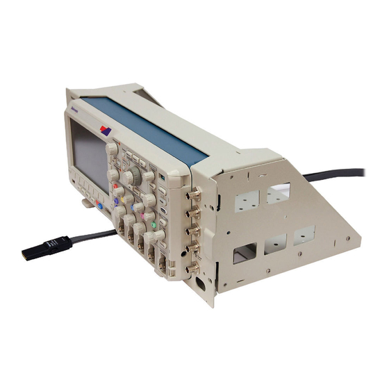
Adhering to these clearance requirements provides the rack-mounted instrument with sufficient clearance for air circulation and accommodation of the power cord and mounting hardware. Failure to provide these clearances can result in overheating and can cause instrument faults or failure. RMD2000 Rackmount Kit... - Page 8 Kit Description Figure 3: Instrument with rack adapter installed RMD2000 Rackmount Kit...
-
Page 9: Installation Instructions
If you need further details for disassembling or reassembling the product, refer to the appropriate product manual. Contact your nearest Tektronix Service Center or Tektronix Factory Service for installation assistance. WARNING. To prevent the rackmounted instrument from tipping forward onto the operator, install the instrument so that the operator will be able to access all of its rear-panel connectors without pushing down on the instrument. -
Page 10: Install
If your application requires that the digital probe be routed to the interior of the rack, place the probe cable(s) in the slot provided before positioning the oscilloscope. RMD2000 Rackmount Kit... - Page 11 The BNC double female jacks are not included as part of this rackmount kit; they must be purchased separately. Align the guides in the front panel bracket and the sides, as shown, and then swing the bottom of the front panel bracket into position. RMD2000 Rackmount Kit...
- Page 12 6-32 X 0.312 flat head Pozidriv screws. Tighten these screws to 8 in-lb. Attach the handles, using two of the 8-32 x 1/2 panhead screws and split lockwashers in each handle. Torque these screws to 16 in-lb. RMD2000 Rackmount Kit...
-
Page 13: Rackmount The Rack-Adapted Instrument Without Rack Slides
Equipment Required: One screwdriver handle and one number two Pozidriv tip. Rack Procedure: Select the appropriate screws for your equipment rack from the kit; 10–32, 12–24, M5, or M6. Assemble them with the recessed and flat washers as shown: RMD2000 Rackmount Kit... -
Page 14: Rackmount The Rack-Adapted Instrument Using Rack Slides
The slide-out tracks permit the rack-adapted instrument to be extended out of the rack for rear-panel and connector maintenance without removing the instrument from the rack. RMD2000 Rackmount Kit... - Page 15 Remove the front (chassis) section of each of the two tracks. Install the front left- and right-side track sections on the instrument using four of the 10-32 x 3/8 inch slotted screws and the nuts with captured lockwashers. Tighten to 28 in-lb. RMD2000 Rackmount Kit...
- Page 16 (10-32) and a bar nut as illustrated. Leave the screws loose so that the overall length of the slide-out track assembly can be adjusted when installing it in the rack. Step-Repeat steps 4 and 5 to assemble the left slide-out track assembly. RMD2000 Rackmount Kit...
- Page 17 Installation Instructions Mount the slide-out track assemblies: Select the mounting position in the rack: Select two 0.5 inch-spaced holes in the front rail, and verify that there is a 3.25 inch clearance above and below those mounting holes. RMD2000 Rackmount Kit...
- Page 18 5 to 28 inch-lb, to fix the front to rear flange spacing of the slide-out track assembly. 11. Mount the left slide-out track assembly: Repeat steps 9 and 10 to mount the left slide-out track assembly. RMD2000 Rackmount Kit...
- Page 19 Retighten the four screws and push the instrument all the way into the rack. If the tracks do not slide smoothly, readjust the level using the method just detailed. d. When leveling is completed, tighten the 10-32 screws using 28 inch-lb of torque. RMD2000 Rackmount Kit...
- Page 20 Select four of the appropriate screws for your equipment rack from the kit; 10-32, 12-24, M5, or M6. b. Secure the instrument in the rack using the screws selected, with the recessed washers and flat washers. End of Document RMD2000 Rackmount Kit...
Need help?
Do you have a question about the RMD2000 and is the answer not in the manual?
Questions and answers