Table of Contents
Advertisement
Advertisement
Table of Contents
Troubleshooting

Related Manuals for EKKO EK20R


Summary of Contents for EKKO EK20R
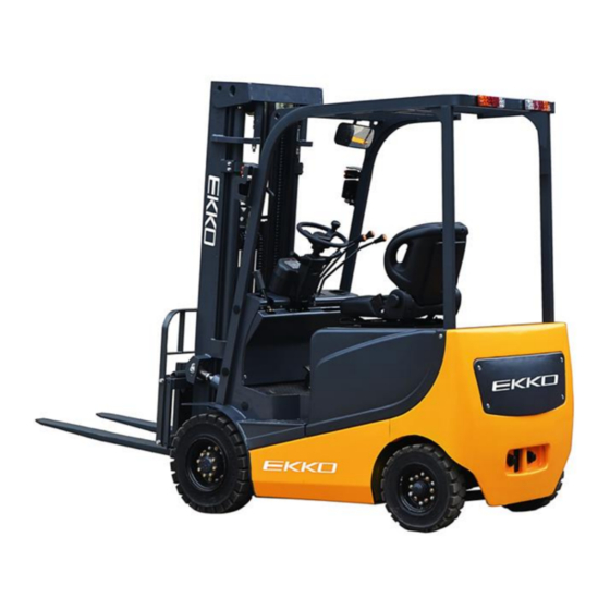
- Page 1 EK20R(EK20RL) Electric Counterbalanced Forklift Manual...
- Page 2 Note Please read this manual before using! Note Please do not use it before completing the installation! Aug.2018...
- Page 3 In order to meet the needs of the national environmental protection request, To reduce industrial pollution and improve productivity, we design and produce new series of EK20R(EK20RL) type Counterbalanced forklift on the basis of absorption of the advantages of domestic & overseas Electric forklift ,they are especially suitable for cargo loading and unloading, handling, stacking, etc for food, bank, light textile, station, port, logistics and other enterprises.
- Page 4 The Statement Our company production model EK20R(EK20RL) type Counterbalanced Electric Forklift is a special motor vehicle used in Factory ,Tourist attractions ,Amusement places which is specified by “special equipment safety supervision regulations” Contents...
-
Page 5: Table Of Contents
1.General Introduction .................... 1 2.Proper usage ......................2 3..Introduction of the product ................4 3.1Model overview ......................4 3.2Product Schematic diagram&Parameter ............4 4.The Schematic diagram of Operating Mechanism ........5 5.Structure ,Principle and Adjustment of main parts of forklift ....7 5.1Drive system ........................ - Page 6 9.1 Repair & Maintenance Safety procedure ............30 9.2 Routine Maintenance ....................31 9.3 Professional Maintenance manual ..............31 9.4 Maintenance ,Recharging and replacement of the Accumulator ... 34 10.Safety Operation And Cautions ..............42 10.1General Rul ........................ 42 10.2 Transportation & Storage ................... 42 10.3 Check before using....................
-
Page 7: General Introduction
1、General Introduction EK20R(EK20RL) type 4 wheel Counterbalanced Electric Forklift adapts battery as the power source ,uses the AC motor as the power to drive the device through the gear transmission. The lifting and tilting of the fork are driven by the DC motor and Hydraulic drive to push the cylinder to lift the cargo. -
Page 8: Proper Usage
The device is suitable for Stacking & Handling cargo on firm ,flat floors The service environment: a. Altitude does not exceed 1200m; b. Indoor room temperature at +5℃ to +40℃ ; c. When environment temperature at +40℃,the relative humidity can’t over 50%,at low temperature ,allow bigger relative humidity d. - Page 9 Operating lighting must be at lest 50LUX Modification Any modification that may affect the truck rated capacity, stability, or safety operations must be approved in advance by the Truck’ s original manufacturer or Its authorized Manufacturer or its successor. This includes the effects of changes such as Braking ,steering ,Visibility, and the addition of removable accessories.
-
Page 10: Introduction Of The Product
3、Introduction of the product 3.1Model overview This manual is a collection of EA type 1.6T counterbalanced Electric forklift (Hereinafter referred to as Forklift ) 3.2Product Schematic diagram & Parameter... - Page 11 Model EK20RL EK20R Power Electric Electric Operator type Rider Rider Load capacity Q (lbs) 4500 4500 Lift height h3 (in) Load center c (in) Distance between fork x(in) 18.8 18.8 backrest and front wheel Wheel base y (in) 55.5 55.5...
-
Page 12: The Schematic Diagram Of Operating Mechanism
Lifting speed Laden/unladen (in/s) 9.9/16 9.9/16 Lowering speed (in/s) 9.5/10.2 9.5/10.2 Laden/unladen Max gradient performance 12/15 12/15 Laden/unladen Service brake Hydraulic Hydraulic pressure pressure Driving motor (kW) Lifting Motor (kW) Battery, According to DIN 43531/35/36 A,B,C,no Battery Voltage/Capacity (V/Ah) 48/420 48/420 Battery weight(±5%)... -
Page 13: Structure ,Principle And Adjustment Of Main Parts Of Forklift
1. Hand braking 2.Combination switch 3.Steering wheel 4.Lifting handle 5.tilting handle 6.Side shift handle 7.Accelerator 8.Foot brake 9.Emergency stop switch 5、Structure ,Principle and Adjustment of main parts of forklift... -
Page 14: Drive System
5.1Drive system 5.1.1Overview The forklift is powered by batter and use a frequency conversion system to convert direct current into Alternating current by controlling the AC motor on the driving wheel . The AC motor converts the high speed and low torque to the low speed and high torque through the gear reducer ,And the driving wheel performs the action. -
Page 15: Steering System
26.Bearing 27.Bearing cover 28.Head bolt Spring washer 30. O-Ring 31.Pad 5.2Steering system 5.2.1Overview Steering system is composed of steering wheel .Steering shaft ,Steering gear, Steering pump0 and steering axle .The steering shaft is connected to the steering gear through the universal joint, And the connecting shaft is connected to the steering wheel through the universal joint ,The steering Column can be tilted back and forth to an appropriate position. - Page 16 piston rod pushes the steering joint through the connecting rod to deflect the steering wheel .then realizing steering . The steering axle is fixed to the tailstock at the rear of the frame by the front and rear pins through the fixing plate ,That is, the vibration damping pad ,So that the axle body can swing around the pin shaft .There is on joint on the left and right sides of the steering axle .and two tapered rollers on the rear hub.
- Page 17 17.Spring washe12 18.BoltM12×40 19. Nut M10×1.25 20.Bolt M10×1.25×40 21.Bent neck grease nipple M6 22.Oil seal 23.Bearing 24. O-ring 25.8×1.8 25.Steering joint kingpin 26.steering joint adjust washer 27.Bearing 28.set pin 29.Right joint 30.Washer 8 31.O-Ring32. Nut M8×1.25 33.Framework oil seal 34.Steering hub 35.Bearing 36Bolt M8×18 37.Flat whasher24...
-
Page 18: Brake Structure &Brake Schematic
Inject grease Preload adjustment 5.2.4 Check after reinstallation of steering system (1) Turn the steering wheel from side to side and see whether the forces are even, and the rotation is steady . (2)Check weather the oil pressure pipe is arranged correctly, and weather the left and right steering is installed in reverse . - Page 19 shoe is pressed against the fixed pin ,the brake shoe moves in the direction of the brake drum. After the fixed pin is pressed ,the frictional force between the friction lining and the brake drum is increased. Because the main brake shoe gives the auxiliary brake shoe a much greater pressure than the brake cylinder pressure ,thereby generating a large braking force .
- Page 20 brake cylinder .So that the cylinder of the pump is properly placed to prevent oil leakage and eliminate the possible air resistance during emergency braking . 1. Lock nut 2. Push Rod 3. Dust cover Locking wire 5. Lock washer 6.
- Page 21 1. Brake baseplate assembly 2. Slack adjuster 3. Friction disc assembly 4. Elastic gasket wire 5. Hand brake lever 6.Return Spring 7. Washer 8.Pole 9. .Return Spring 10. Hand push Rod 11. Compressed spring 12. Adjustment Lever 13.Pressure spring seat 14.
- Page 22 5.3.6 Brake assembly and adjustment essentials Decomposition, assembly ,adjustment of the brake and adjustment of the brake pedal in the dissembled state of the wheel and the hub 1、Decomposition of the brake (1) Remove the support pin ,adjustment lever ,adjustment device and spring on the auxiliary brake shoe.
- Page 23 Figure 5 Figure 6 (7) Decompose the brake cylinder:remove the dust ring,press the piston out of the piston on the other side and press the piston with your fingers .as figure 7 Figure 7 2、 Brake assembly (1) Apply brake fluid to the cup and piston of the brake cylinder and assembly the spring ,piston cup.
- Page 24 (e)Adjusting mechanism threads and other rotating part . (5) Parking brake cable is stuck with E-shaped retaining ring . (6) Install the brake shoe with a fixed spring ,as figure 9 (7) Attached the compression spring to the hand brake lever and attached the push rod to the brake shoe.As figure 10 shoes Figure 9 Figure 10...
- Page 25 Figure 11 Figure 12 3、 The operation test of automatic gap adjuster shown as in Figure 13 (1) First ,the diameter of the brake shoe is close to the specified installation size ,and the adjuster is rotated by the hand to adjust the lever, when the hand is released ,the adjustment lever returns to its original position ,and the adjuster gear does not rotate Note: even when the hand is released ,the adjuster gear returns with the...
- Page 26 (2) Adjust pedal limit bolt .Shown as figure 15,adjust the pedal height (3)Adjust the push rod until the front end of the push rod contacts the master cylinder piston. And then retract 1-2 turns to ensure that the free travel of the pedal is between 10mm-20mm.
-
Page 27: Operating System
Ⅰ、After the new bridge has been working with the main engine for 50h,the gear oil should be replaced .When changing oil ,lean the bridge and add new oil Ⅱ、Check the fastening of each fastener and find that it is loose and tightened immediately Ⅲ、Check for oil leakage at the joint between the wheel axle and the hub .If there is leakage, Reapply the sealant... -
Page 28: Electric System
The fork is mounted on the carriage ,and the carriage moves up and down in the mast by chain drive or the overall movement of the mast ,so that the goods are off the ground or stacked on the shelf .the overall movement of the chain drive and the inner mast achieved by the expansion and contraction of the cylinder, the forklift operating process is realized by controlling the expansion and contraction of the working cylinder(including the tilting... - Page 29 1.Waiting time lamp 2.Trouble alarm lamp 3.battery mark 4.Speed ,power ,time display 5.Temperature alarm lamp 6.Hand brake light 7.Seat lamp 8.Instrument function key 9.Function selection key (UP) 10Function selection key (Down) 11.Parameter adjustment button (small) 12.Parameter adjustment button (large) 13.Exit function key 14Battery indicator 1)Battery The battery indicator lights up—the measured battery level is less than or...
-
Page 30: Hyraulic System
5.6 Hydraulic system The oil pump motor drives the gear pump to provide hydraulic power. The two lift cylinders are responsible for the lifting and lowering of the forks. The two tilting cylinders complete the front and rear tilting movement of the mast , and one side shifting cylinder completes the left and right side shifting of the pallet rack.The control of the lifting, tilting and side-shifting oil circuits is controlled by three handles on the triple valve. -
Page 31: Electrical Schematic Diagram
6、Electrical schematic... -
Page 32: Hydraulic Schematic Diagram
7、Hydraulic schematic... -
Page 33: Operating Specification
8、Operating Specification Before operating the forklift, please be familiar with the dashboard function of each switch/button. 8.1 Start ,Run Parking ○ 1 Insert the key into the key switch, turn to the right, and turn the emergency power off safety switch in the direction indicated by the arrow above the button. -
Page 34: Steering Wheel Angle Front And Rear Adjustment
the lowest position, tighten the parking brake handle, press the safety switch, and pull out the key. (Note that you cannot leave the truck without tightening the hand brake lever). 8.2 The steering wheel Angle adjustment According to the individual operating habits, steering wheel angle can be adjusted . -
Page 35: Hydraulic Joystick Operation
The button of the emergency power off switch is a plastic piece. When pressing down or rotating up, do not use excessive force to avoid damage to the switch. 8.6 The use of speakers and reversing speakers For the safety of driving, vehicle equipped with speakers and reversing speakers. -
Page 36: Maintain Introduction
and slowly move forward, when the fork is fully inserted then parking and stepping on the brakes, operate the lifting handle to raise the weight to a certain height, tilt the mast backwards, slowly reverse the forklift , do not touch the adjacent goods, Lowered the goods to a correct position when the heavy objects completely leave the cargo pile. -
Page 37: Routine Maintenance
point. When the forklift is lifted, appropriate measures must be taken to prevent the forklift from slipping or tipping over (wedges, blocks can be used). Cleaning Operation: Flammable liquid can not be used for cleaning the forklift. Before cleaning, take safety precautions to prevent electric sparks (e.g. sparks caused by short circuit). -
Page 38: Professional Maintenance Manual
The liquid level will be higher when being recharged. 9.2 .2 Check every pole, every cable and their covers. 9.2.3Check if the accumulator box is secured. 9.2.4 Check the forklift for oil leakage. 9.2.5 Check the chain, rollers, fork, oil pipes and horn. 9.2.6 Check the brake. - Page 39 —Replace the hydraulic filter Time interval of maintenance● Check the air gap of the electromagnetic brake Brake ● Check the operation switch to show the function of the device ● and components Check alarm system and safety device ● Electrical Check the cable for damage and the terminal is secure ●...
-
Page 40: Maintenance ,Recharging And Replacement Of The Accumulator
List of maintenance 9.4 Maintenance, Recharging and Replacement of the accumulator The forklift must be parked in a safe location before any operation on the accumulator. 9.4.1 Maintenance Technician Only qualified technician can perform operations on the accumulator such as recharging, maintenance and replacing. Before operation carefully read instruction, manuals including operation manual, replenishment preparation and recharging requirements. - Page 41 Recharging of the accumulator may not work outdoors in cold weather. In this case, move it indoors to perform recharging. 8) If the accumulator will not be in use for a long time, it should be recharged and discharged once every month and it should be fully recharged every time. 9) During recharging or using, the liquid level of electrolyte lowers because of water evaporation, so pure water should be added.
- Page 42 density control work, cleaning of the battery and lead-out piles, etc., which can effectively extend the service life of the battery. Check for water in the battery box and find that the water must be drained immediately. In addition, the battery should not be stored with electrolyte. If you want to store the used and fully charged battery for a short period of time, charge it every other month during the storage period to compensate for the self-discharge of the battery and prevent the battery plate from being vulcanized...
- Page 43 If the electrolyte surface is too low, the distilled water should be replenished in time. Do not add tap water, river water or well water to avoid self-discharge failure caused by impurities; do not add electrolyte, otherwise the electrolyte concentration will increase, and the battery will be shortened the Service life. Note that the electrolyte surface should not be too high to prevent the electrolyte from overflowing during charging and discharging, causing short-circuit failure.
- Page 44 D25 - electrolyte density at 25 ° C Dt - measured density of electrolyte at t °C T—— electrolyte temperature when measuring density 9.4.6 Storage, transportation and installation of the accumulator The forklift must be parked on the level ground steadily. To prevent short circuit, naked cable ends and the terminal posts should be covered with insulated covers.
- Page 45 9.4.7Battery Charging (1)Initial charging (the company's products are generally pre-charged, users can not do this operation) The quality of the initial charge has a great influence on the battery, and it must be operated by a experienced personnel . The unused battery should be charged before use. Clean the surface of the battery before initial charging and check for damage.
- Page 46 The temperature of the electrolyte during charging should not exceed 45 ° C. When the temperature is close to 45 ° C, the charging current should be halved or suspended. Continue charging after the electrolyte temperature drops below 35 °C. However, it is necessary to extend the charging time appropriately;...
- Page 47 charged. (For the observation of the charging status, please refer to the manual of the charger) In order to understand the condition of the battery in time, it is recommended to establish a charge and discharge record for each battery, so as to provide a useful basis for the judgment of the failure of the battery in the future.
-
Page 48: Safety Operation And Cautions
The battery that is normally used is charged once every 2 to 3 months. A battery that has not been used for a long time should be balanced charged before use. 10、Safety caution 10.1 General rule 10.1.1 Requirements for drivers: The operator must have the operating qualification of the forklift (approved by the relevant department) before driving the forklift 10.1.2 The operator must read the entire contents of the instruction manual... -
Page 49: Check Before Using
○ 2 After pulling up the stationary truck, the front and rear wheels are well padded. ○ In case of long-term disuse, the battery should be replenished every 15 days. 10.3 Check before Using 10.3.1 If the new forklift is damaged during transportation, please do not put it into use and contact the supplier in time for proper treatment. - Page 50 safely operated (e.g.: wheel wear or brake failure), then it must stop using until it is fully repaired. 10.4.5 Safe operation and environmental protection: inspection and maintenance must be performed in accordance with the time intervals on the maintenance list. Parts of the forklift cannot be changed without any permission, especially safety devices.
- Page 51 10.4.12 the use in the elevator and loading platform maneuvering: if there is sufficient loading capacity, does not affect the operation of the vehicle, and agreed by the user of the forklift, lift and loading platform that can be used for forklift transport.
-
Page 52: Toubleshooting
approve the changes, nameplates, labels and markings of Operation and Maintenance Manual must be modified as well 11、Service Manual 11.1Hand and foot brake common faults and troubleshooting Fault Cause Troubleshooting 1、Improper brake pedal Adjust it position 2、Brake system oil leakage Overhaul or replace 3、Air is mixed in the brake exhaust... -
Page 53: Steering System Common Faults And Troubleshooting
2、Impurities are mixed into Check and replace brake the brake fluid fluid 3、Hand brake position cable Replace or repair deformation, joint dropout 11.2steering system common faults and troubleshooting Fault Cause Troubleshooting 1、There is air on Steering system Exhaust air hydraulic line components 2、oil level is too low ,inhaling air Add oil and exhaust air 3、The divert valve hole is blocked... -
Page 54: Lifting System Common Faults And Troubleshooting
2、Suction tank or oil filter plugged Clean and replace 11.3lifting system common faults and troubleshooting Fault Cause Troubleshooting 1、The gap between upper end Reduce adjustment roller of outer mast and channel gasket steel of inner mast is too large > 2.The gap between the lower end increase adjustment roller of the outer mast and the... -
Page 55: Electric System Common Faults And Troubleshooting
Or can't lift and stuck 4、Oil leakage in the suction pipe Repair welding, bottom of the filter in the fuel tank leakage 5、Loose pipe joint tighten 6、 Oil pump gear and pump body Check the cleanliness of are excessively worn, and the the oil, requiring 9-11 clearance is too large 7、... -
Page 56: Gearbox Failure Reasons And Troubleshooting
Horn rang for long time 1、Horn switch contact long pass 1、bad reversing buzzer Reversing buzzer does not ring 2、Poor contact of the reverse switch 3、Poor line connection 11.5Gearbox common faults and troubleshooting fault troubleshooting 1.The friction plate is stuck or worn. Check the friction plates for gluing, uneven contact or warpage. - Page 57 1.The operating mechanism is not flexible when stuck 1Check the operating lever 2.Stem jammed with dirt 2.Cleaning valve, fuel tank 3.Return spring deformation or and piping Valve stem fracture 3.Remove the back cover and cannot be 4.External force causes replace the spring reset deformation of the stem 4.Replace stem or valve...
-
Page 58: Gear Pump Failure Reasons And Troubleshooting
loose again, tighten the nut to the 6.oil pump malfunction specified torque. 6.replace oil pump 1.The system is repeatedly operated for a while and then 1.Air in the hydraulic system discharged. 2.Oil pump suction air 2.Check oil pump suction test Overflow 3.Suction pipe resistance is too 3Check the cause of negative... - Page 59 damaged, and the air is taken in. 7.Change the direction of the oil 7.Oil pump is not in the wrong pump to make the speed to the direction or the speed is too high specified value 8.Oil leakage on the suction side 8Check the oil suction part and its seal, replace the failed seal There is...
-
Page 60: Other Common Faults And Troubleshooting
the oil level, and there are a lot the season, or heating of bubbles in the oil. 4.Adjust the coaxially of the two 3.The viscosity of the oil is too axes high, and the oil temperature is 5.Disassemble the oil pump and too low turn the driven gear around 4.The coaxially between the... -
Page 61: Aftersales
12.After-sales service If there is a problem that cannot be solved by professional maintenance staff, please contact our after-sales service staff at (877)232-6517 Note: the manufacturer reserves the right of interpretation. If have change not notice additionally!
Need help?
Do you have a question about the EK20R and is the answer not in the manual?
Questions and answers