
Related Manuals for EKKO EK20LI Series


Summary of Contents for EKKO EK20LI Series
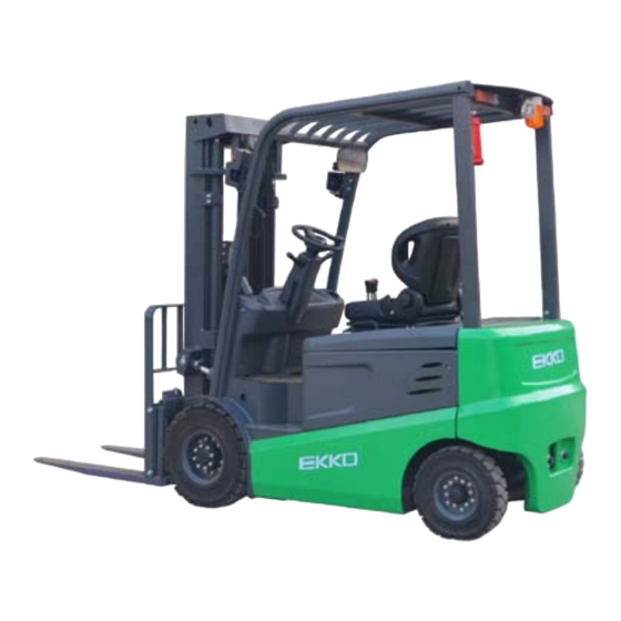
- Page 1 The Specification EK20LI/EK22LI Series Electric Forklifts Note Please read this manual before using! Note Please do not use it before completing the installation!
- Page 2 Introduction To meet the needs of the national environmental protection request to reduce industrial pollution and improve productivity, we designed and produced a new series of EK20Li/EK22Li type counterbalanced forklift based on absorption of the advantages of domestic & overseas electric forklift. They are especially suitable for cargo loading and unloading, handling, stacking, etc for food, bank, light textile, station, port, logistics and other enterprises.
- Page 3 The Statement Our production model EK20Li/EK22Li type 4500/5000lbs counterbalanced electric forklifts is a special motor vehicle used in factory, tourist attractions, amusement places which is specified by “special equipment safety supervision regulations”.
-
Page 4: Table Of Contents
Contents 1.General Introduction ..................1 2.Proper use ......................3 3.Introduction of the product ................4 4.The Schematic diagram of Operating Mechanism ........7 5. Structure ,Principle and Adjustment of main parts of forklift ....8 6.Electrical schematic ..................25 7.Hydraulic schematic ..................26 8.Operating Specification .................. -
Page 5: General Introduction
1.General Introduction EK20Li/EK22Li type 4 wheel Counterbalanced Electric Forklift adapts battery as the power source, uses the AC motor as the power to drive the device through the gear transmission. The lifting and tilting of the fork are driven by the DC motor and Hydraulic drive to push the cylinder to lift the cargo. - Page 6 The device is suitable for Stacking & Handling cargo on firm, flat floors The service environment: a. Altitude does not exceed 47inch. b. Indoor room temperature at +5℃ to +40℃. c. When environment temperature at +40℃, the relative humidity can’t over 50%, at low temperature, allow bigger relative humidity d.
-
Page 7: Proper Use
2.Proper use Please use the Counterbalanced electric forklift according to this specification. The Forklift described in this manual is a self-controlled series of Counterbalanced Electric forklift. With Multi-way valve control forklift lifting, Forward & backward tilting, side shifting etc. function. Improper use can cause personal injury or machine damage. -
Page 8: Introduction Of The Product
3.Introduction of the product 3.1Model overview This manual is a collection of EK20Li/EK22Li type 4500/5000lbs counterbalanced Electric forklift (Hereinafter referred to as Forklift) 3.2Product Schematic diagram & Parameter... - Page 9 Manufacturer EKKO EKKO EKKO EKKO Model EK20-189LI EK20-216LI EK22-189LI EK22-216LI Power unit Electric Electric Electric Electric Operation Tower Rack Tower Rack Tower Rack Tower Rack Rated traction weight Q (lbs.) 4500 4500 5000 5000 Load center c (Inch) 19.68 19.68 19.68...
- Page 10 Overall width 42.12/42.91 42.12/42.91 42.12/42.91 42.12/42.91 (Inch) s/e/l Fork dimensions 1.57/4.72/42.12 1.57/4.72/42.12 1.57/4.72/42.12 1.57/4.72/42.12 (Inch) Width of fork carriage 34.25 34.2519 34.25 34.2519 (Inch) Min. Ground clearance 3.15 3.1496 3.15 3.1496 (Inch) Aisle width with pallet 156.30 156.2989 156.30 156.2989 1000 x 1200 across forks (Inch) Aisle width with pallet 800...
-
Page 11: The Schematic Diagram Of Operating Mechanism
4.The Schematic diagram of Operating Mechanism The Forklift uses battery as power source, uses electric and hydraulic to travelling, & Lifting, Forward & backward tilting and steering Operating Mechanism diagram: 1. Hand br a king 2. Combination switch 3. Steering wheel 4. -
Page 12: Structure ,Principle And Adjustment Of Main Parts Of Forklift
5. Structure, Principle and Adjustment of main parts of forklift 5.1Drive system 5.1.1Overview The forklift is powered by battery and use a frequency conversion system to convert direct current into alternating current by controlling the AC motor on the driving wheel. - Page 13 18. Stop washers for round nuts 19. Spring washer 20. Gasket set 21. P ad s et 22. be aring s eat 23. Bearing 24. bushing 25. Oil seal 26. bearing 27. bearing cover 28. Head Bolt 29. Spring washer 30.
- Page 14 cavity. 1.Bolt M16×12 2.Spring washer 6 3.Tighten pin 4.Connecting rod 5.Joint Bearing 6.bushing 7.left knuckle 8.steering axle 9.Steering oil cylinder 10.Cotter pin5×50 11.Groove nut 12.Flat washer27 13.Adjustable washer 14.Bearing 15.Pin 16.Flat washer12 17.Spring washer 12 18.Bolt M12×40 19. Nut M10×1.25 20.Bolt M10×1.25×40 21.Curved neck grease nozzleM6 22.Oil seal 23.Bearing...
- Page 15 (1) As the picture shows, Grease the inner cavity of the hub, The inner and outer bearings, and the hub cap, and apply some grease to the lip of the oil seal. (2) Fixing the outer ring of the bearing to the hub and attaching the hub to the steering joint shaft.
- Page 16 5.2.4 Check after reinstallation of steering system (1) Turn the steering wheel from side to side and see whether the forces are even, and the rotation is steady. (2) Check whether the oil pressure pipe is arranged correctly, and weather the left and right steering is installed in reverse.
- Page 17 to walk, and the control circuit can be connected. Parking brake has the function of adjusting tightness. 5.3.2Brake pedal The brake pedal portion is constructed as shown in the figure ,and the pedal converts in the pedaling force acting on the pedal into the brake oil pressure by the push rod of the master cylinder .
- Page 18 1.Lock n ut 2. P ush R od 3. D ust c over 4.Locking wire 5. Lock washer 6. A uxiliary cup 7. pi s ton 8. M aster c up 9. S pring 10. C heck va lve 11. V alve s eat 12.
- Page 19 10. Hand push Rod 11. C ompressed s pring 12. Adjustment Lever 13. Pressure spring s eat 14. S pring 15.Pressure s pring Cover 16.Spring 17.Pressure s pring s eat 18.Pressure s pring L ever 19.Support pi n 20.Washer 21.Rubber pl u g 22.Brake c able a ssembly 23.Bolt M 8×16 24.Spring W asher 8...
- Page 20 Figure 1 Figure 2 (3) Remove the anchor spring on the main brake show, as figure 3 (4) Remove the main brake shoe and the auxiliary brake shoe, Remove the adjuster and adjuster spring at the same time, as figure 4 Figure 3 Figure 4 (5) Remove the brake pipe from the brake cylinder, then remove the mounting bolts of the brake cylinder and...
- Page 21 Figure 5 Figure 6 Decompose the brake cylinder: remove the dust ring, press the piston out of the piston on the other side and press the piston with your fingers. Figure 7 Brake assembly 2、 (1) Apply brake fluid to the cup and piston of the brake cylinder and assembly the spring, piston cup.
- Page 22 Figure 7 Figure 8 Attached the compression spring to the hand brake lever and attached, as figure Figure 9 Figure 10 (8) Install brake shoe guide to support pin and then install brake shoe return spring, Install the main hoof first, and then the auxiliary hoof, As shown in figure 11 (9) Install adjuster, adjuster spring, ejector pin, ejector return spring, please pay attention to following point :...
- Page 23 (11) Measure the inner diameter of the brake drum, the out diameter of the brake shoe, and adjust the adjuster to make sure the difference between the inner diameter of brake drum and the outer diameter of friction plate of the brake shoe is 0.3mm-0.5mm, as figure 12 shows.
- Page 24 (3) Adjust the push rod until the front end of the push rod contacts the master cylinder piston. And then retract 1-2 turns to ensure that the free travel of the pedal is between 10mm-20mm. (4) Lock the push rod nut and the pedal limit bolt nut. figure figure (5) Brake switch adjustment as shown in figure 16...
- Page 25 Ⅰ、After the new bridge has been working with the main engine for 50h, the gear oil should be replaced. When changing oil, lean the bridge and add new oil Ⅱ、Check the fastening of each fastener and find that it is loose and tightened immediately Ⅲ、Check for oil leakage at the joint between the wheel axle and the hub.
- Page 26 5.5 Electrical system 5.5.1Overview The electrical system mainly includes battery pack, traction motor, pump motor, traction motor controller and pump motor controller, steering combination switch, multi-way valve block controller, display instrument, combined control switch, instrument, and lighting device. etc. 5.5.2 Display Curtis’s instrument is used to realize the auxiliary control function and provide the driver with vehicle condition display interface.
- Page 27 Curtis meters provide the operator with some easy information about the health of the vehicle's mechanism. As figure 1/Parameter adjustment key (left turn) 2/Speed mode switch key/Parameter Adjustment key (up turn) 3/Parameter adjustment key (right turn) 4/Parameter adjustment key (scroll down) 5/Parameter Adjustment key (Confirm) 6/Turtle speed indicator 7/Parking light...
- Page 28 5.6 Hydraulic system The oil pump motor drives the gear pump to provide hydraulic power. The two lift cylinders are responsible for the lifting and lowering of the forks. The two tilting cylinders complete the front and rear tilting movement of the mast, and one side shifting cylinder completes the left and right side shifting of the pallet rack.
-
Page 29: Electrical Schematic
6. Electrical schematic... -
Page 30: Hydraulic Schematic
7. Hydraulic schematic... -
Page 31: Operating Specification
8. Operating Specification Before operating the forklift, please be familiar with the dashboard function of each switch/button. 8.1 Start, Run & Parking Insert the key into the key switch, turn to the right, and turn the emergency power off safety switch in the direction indicated by the arrow above the button. - Page 32 Determine the vehicle forward or backward. Toggle joystick in place, right foot will tread the foot pedal accelerator to make the forklift slowly forward or backward. Continue down the pedal, the forklift 's speed to speed up. Started never put foot accelerator jammed on to the end, in order to avoid the vehicle out of control. 8.4 Brake pedal operation When the moving forklift needs to stop, release the pedal accelerator, move the right foot to the middle of the foot brake pedal, and the vehicle will stop after braking...
- Page 33 (2) Tilt lever: a. Back tilt (back pull); B. stay in place; C. Forward tilt (push forward) Every joystick can only Operate one hydraulic circuit. when the lever is moved, the attached micro switch will start the oil pump motor to rotate at the same time and output the hydraulic oil with pressure to make the relevant hydraulic components move.
-
Page 34: Maintenance And Service Manual
9.Maintenance and Service Manual The part on the forklift , especially the safety devices, shall not be modified without permission, and the speed of the forklift must not be changed.All spare parts supplied by the original manufacturer are subject to strict quality inspection.In order to ensure the safety and reliability of the forklift, please use the original accessories.Replacement parts, including all oils, must be collected and disposed of in accordance with local environmental and health laws and regulations. - Page 35 Lifting chain and rollers: Chain and rollers will be worn quickly without good lubrication.Perform periodic lubrication according to following maintenance table. Shorten the lubrication period under adverse operation conditions (such as in dusty and hot environment). Hydraulic oil pipe: The oil pipe must be changed every 6 years. When change the hydraulic assembled parts, the oil pipe should be also changed.
- Page 36 List of Maintenance Time interval of maintenance● ● Check the air gap of the electromagnetic brake Brake ● Check the operation switch to show the function of the device and ● Check alarm system and safety device ● Check the cable for damage and the terminal is secure Electrical ●...
- Page 37 9.4 Maintenance, Recharging and Replacement of the accumulator The forklift must be parked in a safe location before any operation on the accumulator. 9.4.1 Maintenance Technician Only qualified technician can perform operations on the accumulator such as recharging, maintenance and replacing.
- Page 38 10) If individual cell fails, identify the cause, and repair the cell immediately. Replace the cell when it cannot be repaired. 11)The site for recharging should be well ventilated. It is prohibited to smoke or use open fire, avoiding the risk of hydrogen explosion.
- Page 39 Check the battery case for cracking and damage, and the pole and lead chuck should be free from burning. Wipe the external dust of the battery with a cloth. If there is electrolyte on the surface, wipe it off with a cloth or rinse it with hot water, then wipe it with a cloth.
- Page 40 Can be corrected as follows: The standard temperature of the electrolyte (25 ° C) is converted according to the following formula: D25 = Dt + 0.0007(t - 25) D25 - electrolyte density at 25 ° C Dt - measured density of electrolyte at t °C T——...
-
Page 41: Safety Caution
10.Safety caution 10.1 General rule 10.1.1 Requirements for drivers: The operator must have the operating qualification of the forklift (approved by the relevant department) before driving the forklift 10.1.2 The operator must read the entire contents of the instruction manual before using it, and drive the truck after fully understanding the operation method. - Page 42 10.4 Safe Operation 10.4.1Requirements for drivers: The forklift must be operated by a trained staff. He can demonstrate the operation of the goods to the users and can clearly guide the user how to operate the forklift. 10.4.2 Drivers’ rights, obligations, and responsibilities: Has been trained by the operation of the vehicle, the driver must be clear of his rights and obligations;...
- Page 43 10.4.10 distance between forklift: Keep in mind that the forklift in front could suddenly stop at any time, so please keep an appropriate distance. 10.4.11 headroom: When the headroom is below the cargo or mast, it is prohibit using the forklift. 10.4.12 the use in the elevator and loading platform maneuvering: if there is sufficient loading capacity, does not affect the operation of the vehicle, and agreed by the user of the forklift, lift and loading platform that can be used for forklift transport.
-
Page 44: Service Manual
11.EK20Li/EK22Li Service Manual 11.1Hand and foot brake common faults and troubleshooting Fault Cause Troubleshooting 1、Improper brake pedal position Adjust it 2、Brake system oil leakage Overhaul or replace 3、Air is mixed in the brake system exhaust 4、Brake shoe clearance is not adjusted Adjust it Poor braking 5、Deformation, damage or excessive... -
Page 45: Steering System Common Faults And Troubleshooting
2steering system common faults and troubleshooting Fault Cause Troubleshooting 1、There is air on Steering system hydraulic line Exhaust air components 2、oil level is too low, inhaling air Add oil and exhaust air 3、The divert valve hole is blocked and the spool Clean and replace is stuck 4、Steering cylinder piston rod bending... -
Page 46: Lifting System Common Faults And Troubleshooting
lifting system common faults and troubleshooting 11.3 Fault Cause Troubleshooting 1、The gap between upper end roller of outer Reduce adjustment gasket mast and channel steel of inner mast is too large > 1mm 2.The gap between the lower end roller of the increase adjustment gasket outer mast and the channel steel of the inner mast is too large >... -
Page 47: Electrical System Common Faults And Troubleshooting
9、Diverter valve is improperly diverted Adjust Electrical system common faults and troubleshooting 11.4 1、Poor contact of the key switch 2、break line Turn on the key switch without voltage 3、Poor contact of connectors 4、Loose battery connector 1、break line Stepping on the accelerator pedal, the forklift does no t 2、Poor contact of connectors move 3、Poor contact of the direction switch... -
Page 48: Multi Valve Common Faults And Troubleshootin
3The part is damaged and cracked. Replace it. Multi valve common faults and troubleshooting 11.6 Fault Cause troubleshooting 1.Lip seal wear 1.Replace the lip seal 2.Damage to the stem seal 2.Replace stem or disc assembly 3.The lip seal is embedded with foreign matter such 3.Clean foreign matter such as paint as paint and dust. - Page 49 4.Steering gear malfunction 4.replace the steering gear 1.Cleaning valves, fuel tanks, piping, etc. 1.There is a foreign matter stuck between the main 2.Serious hydraulic oil pollution, cleaning valve core of the relief valve or the overload valve No action in hydraulic system and the valve seat.
-
Page 50: Gear Pump Common Faults And Troubleshooting
Gear pump common faults and troubleshooting 11.7 Fault Cause Troubleshooting 1.Replace the oil filter with a suitable flow 1.Suction oil filter has a small flow area or is area or clean the blocked oil filter blocked by foreign matter 2.The fuel tank is filled with hydraulic oil as 2.Tank level is too low required 3.High installation position of oil pump;... -
Page 51: Other Common Faults And Troubleshooting
Fault Cause troubleshooting 1、 The amount of oil such as hydraulic oil and gear oil Fuel to the required level does not meet the requirements. Abnormal sound 2、Front and rear hub bearings are loose and broken Tighten the bearing and lock during moving the nut back to about 1/8 turn. -
Page 52: After-Sales Service
rotate. The fracture updates the 3、Gearbox, gear, friction plate damage replace 4、Differential and cross shaft damage replace 5、Loose fasteners tighten 12.After-sales service If there is a problem that cannot be solved by professional maintenance staff, please contact our after-sales service staff at +1(877)232-6517 Note: the manufacturer reserves the right of interpretation.
Need help?
Do you have a question about the EK20LI Series and is the answer not in the manual?
Questions and answers