
Related Manuals for EKKO EK18GS


Summary of Contents for EKKO EK18GS
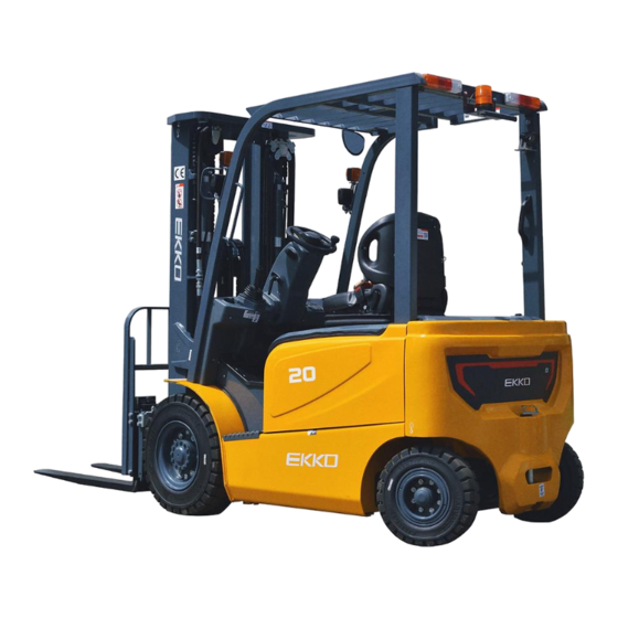
- Page 1 Electric Counterbalance Forklift Truck Series EK18GS / EK18GSH / EK20GS / EK25GB / EK25GHB / EK30GB / EK35GB Operation and Maintenance Manual...
- Page 2 Foreword The EKKO counterbalance electric forklift trucks are new series of products developed by our company to meet the market demand, based on the advantages of electric forklift trucks at home and aboard and in combination with our existing products and mature technologies. They are characterized by environmental protection, maintenance-free, long service life, high efficiency and energy saving, high safety, etc.
- Page 3 Please strictly abide by the regulations and precautions in this Manual in use, so that your forklift will be in the best working condition. This Manual describes standard and optional vehicles, and the real object shall prevail for non-standard vehicles. In case of any technical questions, please consult the manufacturer.
-
Page 4: Table Of Contents
Table of Contents Driving, Operation and Safety Procedures of Forklift Truck .........1 . Basic Principles....................1 . Transportation of Forklift truck ...............1 . Storage of Forklift truck...................1 . Preparation before Use..................1 . Operation of Forklift truck................2 . Routine Maintenance of Forklift Truck ............4 . -
Page 5: Driving, Operation And Safety Procedures Of Forklift Truck
I. Driving, Operation and Safety Procedures of Forklift Truck 1 . Basic Principles Forklift truck drivers and management personnel must keep in mind the concept of "safety first", and carry out safe and standard operation according to the Operation and Maintenance Manual and Driver's Manual of the forklift truck. -
Page 6: Operation Of Forklift Truck
(3) Check the sound, light and alarm devices: various lights, buzzers and horns (including rear handle buttons); (4) The drive and reverse gear handle shall be in the middle position (neutral position); (5) Check the state of each handle and pedal; (6) Make preparations before startup;... - Page 7 (8) Pay attention to pedestrians, obstacles and potholes when driving, and pay attention to the upper clearance of the forklift; (9) No one is allowed to stand on the fork, and the truck shall not carry persons other than the driver; (10) No one is allowed to stand or walk under the fork;...
-
Page 8: Routine Maintenance Of Forklift Truck
(20) If pneumatic tires are equipped, the tire inflation pressure shall be the pressure value specified on the "Tire Pressure" plate; (21) The maximum noise value outside the forklift truck shall not be more than 0 dB(A), and the test method is stated in JB/T3300; (22) Be familiar with and master the contents of various signs on the forklift. -
Page 9: Description Of Frame Number Printing Position
Filling volume Name Grade, code and service temperature Viscosity Anti-freezing hydraulic 1 .5-2t (E):33 grade hydraulic oil 40# oil YYY-LPL-HS32 Hydraulic oil 2-2.5t: 42 Operating Normal temperature Cold storage 3 -3.8t: 45 condition environment environment Brake fluid 4604 synthetic brake fluid GB12891 HZY4 3 # general purpose lithium grease (-20°C~+120°C) Grease Or 2# L-XDCBB2 low-temperature grease... -
Page 10: Load Curve
is located in the middle-upper area on the right wall plate of vehicle body, and the frame number of the battery side taking (side pulling and side shoveling) model is located in the middle-upper area on the left wall plate of vehicle body, as shown in the following figure. - Page 11 (2) Rated load chart of forklift 1 .5t Two-stage Mast 1.5t Three-stage Mast 1 .8t Two-stage Mast 1.8t Three-stage Mast...
- Page 12 Small 2t Two-stage Mast Small 2t Three-stage Mast 2 t Two-stage Mast 2t Three-stage Mast 2 .5t Two-stage Mast 2.5t Three-stage Mast 3 t (M type) Two-stage Mast 3t (M-type) Three-stage Mast...
- Page 13 3 t (S-type) Two-stage Mast 3t (S-type) Three-stage Mast 3 .5t (M-type) Two-stage Mast 3.5t (M-type) Three-stage Mast 3 .5t (S-type) Two-stage Mast 3.5t (S-type) Three-stage Mast 3 .8t Two-stage Mast 3.8t Three-stage Mast...
-
Page 14: Main Technical Parameters Of Forklift Truck
II. Main Technical Parameters of Forklift Truck Outline Drawing of the Vehicle... - Page 15 List of Main Technical Parameters Model EK18 EK18 EK20 Configuration No. A3H4-M/A5H4-M A5H4-S A5XH4-S Rated lifting capacity 1500 1800 1500 1800 2000 Load center distance Power type Battery Driving mode Seat type Tire type Pneumatic tire Front wheel size 6.50-10-10PR 6.50-10-12PR Rear wheel size 16x6-8-10PR...
- Page 16 Lifting motor power 10.6 (S3-15%) Battery voltage/rated V/Ah 48/480 48/400 48/420 capacity Battery weight Total weight 3300/2585 3175/2395 3050/2345 3100/2395 3125/2345 (with/without battery) List of Main Technical Parameters EK20 EK25 EK20 EK25 Model Configuration No. A3H4-M/A5H4-M A5H4-S Rated lifting capacity 2000 2500 2000...
- Page 17 Lifting speed (full load/no load) 0.290/0.440 0.260/0.400 15/25 15/25 Max. gradeability, full load/no load 17/26 15/25 Power of drive motor (S2-60 min) Lifting motor power (S3-15%) Battery voltage/rated capacity 48/600 48/500 Battery weight Total weight (with/without battery) 4030/3100 4190/3260 3940/3100 4100/3260 List of Main Technical Parameters Model...
- Page 18 Lift height (standard) 3000 Body length (excluding 2567 2572 2567 2572 2612 fork) Body width 1260 1392 Height of overhead guard 2180 2185 Travel speed (full load/no 1 4.5/15 12/13 14.5/15 load) Lifting speed (full load/no 0.290/0.440 0.260/0.400 0.260/0.400 load) Max.
-
Page 19: Structure, Principle, Adjustment And Maintenance
III. Structure, Principle, Adjustment and Maintenance 1 . Transmission System 1 .1 Overview The transmission system of the electric forklift truck consists of a drive axle (Fig. -2) and a reducer (Fig. 1-3). The drive axle is used to support and bear the mast and frame. - Page 20 1 .3 Drive axle assembly The drive axle assembly is composed of axle housing, axle shaft, hub, brake and wheel, and is installed in the front of the frame. The 1.5-3.8t axle housing is of an integral casting structure. The hub is supported on the axle housing by a conical roller bearing, and is connected to the tire with bolts and nuts.
- Page 21 Fig. 1-3 Reducer and Differential (1.5-3.8t) .4 Installation of hub (1) Fill the hub with 100cc grease and install it on the axle housing. See Fig. (2) Tighten the inner lock nut with a torque of about 1kg.m and then return it for 1/8 turn.
-
Page 22: Brake System
(4) Install the lock plate and lock nut, and pull up the lock plate. Fig. 1-5 Measurement of Initial Torque (5) Tire assembly Install the connecting rod and cap on the tire, and assemble the rim. Pay attention to the following conditions: Note: a) The air valve rod is at the rim gap and faces outward;... - Page 23 state. 2 .1.1 Service brake system The service brake system is mainly composed of brake pedal, master cylinder, slave cylinder, brake fluid reservoir, pipeline and brake. The principle of service brake is shown in Fig. 2-1.1, and the structure of brake pedal is shown in Fig. 2-1.2. The brake pedal is installed on the bracket assembly through the pin shaft.
- Page 24 Fig. 2-1.2 Service Brake System .1.2 Parking brake system The parking brake device is assembled in the wheel brake and is composed of a pull rod and a stay rod. The pull rod is installed on the main brake shoe side by a pin, and the action of the pull rod is transmitted to the auxiliary brake shoe side through a stay rod, as shown in Fig.
- Page 25 2 .1.3 Brake master cylinder The master cylinder includes a valve seat, a one-way valve, a return spring, a cup, a piston and an auxiliary cup. The end is fixed with a lock washer and a locking wire; the outside is protected with a rubber dust cover; the master cylinder piston is operated through a push rod by operating a brake pedal.
- Page 26 Fig. 2-3 Brake Master Cylinder 2 .1.4 Brake The brake is a double-shoe brake, which is installed on both sides of the box axle assembly. The brake consists of 2 groups of brake shoes, brake slave cylinder and slack adjuster. One end of the brake shoe is in contact with the fixing pin, and the other end is in contact with the clearance adjusting device.
- Page 27 the vehicle moves forward, as shown in Fig. 2-4.2. Fig. 2-4.1 Action in Forward Mode Fig. 2-4.2 Action in Backward Mode (2) Clearance self-adjusting mechanism The clearance self-adjusting mechanism can keep proper clearance between the friction plate and the brake drum. The structure is shown in Fig. 2-5. The clearance self-adjusting mechanism only acts during reversing and braking.
- Page 28 ▲ Action of clearance self-adjusting mechanism When the forklift truck moves backward, brake operation is carried out. The auxiliary brake shoe contacts with the main brake shoe and rotates together to make the pull rod turn right around Point A. As shown in Fig.
- Page 29 Fig. 2-7 Brake Assembly (1) Brake cable assembly (2) Washer 8 (3) Bolt M8x20 (4) Pawl (5) Pawl pin shaft (6) Torsion spring (7) Hand brake push rod (8) Spring (9) Rear brake shoe with (10) Spring wire device (11) Brake shoe return spring (12) Guide block friction plate assembly (13) Guide plate...
- Page 30 6 0~75 mm. After depressing the pedal, the clearance between the pedal and the front bottom plate shall be greater than 20 mm; (3) Step on the brake pedal and lengthen the push rod until the front end of the push rod contacts the piston of the master cylinder;...
- Page 31 2 .2 Main points of brake disassembling, assembling and adjustment This section describes the disassembling, assembling and adjustment of the brake and the adjustment method of the brake pedal when the wheel and hub are disassembled. This section is applicable to 2.5t brake. Although the structure of regulators is different for other models, the maintenance methods are basically the same.
- Page 32 (4) Remove the main brake shoe and auxiliary brake shoe. Remove the adjuster and adjuster spring at the same Fig. 2-13 time. (5) Remove the brake pipe from the brake slave cylinder. Then remove the mounting bolts of the brake slave cylinder and remove the brake slave Fig.
- Page 33 2 .2.2 Brake inspection Inspection of parts and components, repair or replacement of damaged parts and components (1) Inspect whether there is rust on the inner surface of the slave cylinder and the periphery of the piston. Then measure the clearance between the piston and the cylinder.
- Page 34 (5) Visually inspect the inner surface of the brake drum. In case of damage or eccentric wear, grind and correct it, and replace it if it exceeds the correction limit. Unit: mm 1 .0-2 t (E) 2.0-2.5t 3.0-3.8t Standard value Φ254 Φ314 Φ310...
- Page 35 Fig. 2-20 (5) The parking brake cable is stuck with an E-ring. (6) Install the brake shoe with the fixing spring. (7) Install the pressure spring on the push rod of the hand brake, and then install the push rod on the brake shoe. Fig.
- Page 36 d) The lower end of the adjusting lever must be in contact with the adjuster teeth. Fig. 2-23 (10) Connect the brake oil pipe to the slave cylinder. (11) Measure the inner diameter of the brake drum and the outer diameter of the brake shoe, and adjust the adjuster so that the difference between the inner diameter of the brake drum and the outer diameter of the brake shoe friction plate is 1 mm.
- Page 37 a) Fix the adjusting lever, ejector rod, ejector rod spring and compression spring seat; b) Check whether the ejector rod return spring and adjuster spring are damaged, whether the rotation of the adjuster gear and its meshing parts are excessively worn or damaged, and whether the lever is in contact with the gear, and replace damaged parts.
-
Page 38: Steering System
adjusted ) Failure of slave cylinder Repair or replace ) The brake shoe return spring damaged Replace ) Brake drum deflection Repair or replace ) Oil leakage of brake system Repair or replace ) Clearance of brake shoe improperly Adjust the adjuster Braking adjusted failure... - Page 39 displacement, which is transmitted to the steering gear through the steering shaft. According to the turning angle of the steering wheel, the steering gear transmits the appropriate volume of pressure oil to the steering cylinder through the pipeline, and the oil cylinder pushes the steering wheel through the steering trapezoidal mechanism to realize steering.
- Page 40 The steering trapezoid adopts a crank slider mechanism, and the steering knuckle is pushed by the cylinder piston rod through the connecting rod to offset the steering wheel, thus realizing steering. The steering axle is fixed on the tail frame at the rear of the frame by bolts after the installation of damping blocks on the front and rear end plates, so that the axle body can swing around the pin shaft on the end plate, and a certain damping effect can be obtained due to the damping blocks.
- Page 41 (1) Steering cylinder The steering cylinder is a double-acting piston cylinder. Both ends of the piston rod are connected with the steering knuckle through the connecting rod. The pressure oil from the full hydraulic steering gear moves the piston rod left and right through the steering cylinder to realize left and right steering.
- Page 42 Fig. 3-4 Hub .5 Installation, commissioning, and maintenance .5.1 Adjustment steps of the pre-tightening load of the steering wheel bearing (1) As shown in Fig. 3-5, apply grease to the inner cavity of the hub, inner and outer bearings and hub cover, and apply some grease to the lip of the oil seal; (2) Fix the bearing outer ring around the hub, and install the hub to the steering knuckle shaft;...
- Page 43 Fig. 3-5 Adding Lubricating Grease and Pre-tightening Load Adjustment (6) Tap the hub gently with a wooden hammer, rotate the hub by hand for 3~4 turns to ensure stable rotation, and measure the rotating torque of the hub, which is 2 .94~7.8N.m (0.3~0.8kgm);...
- Page 44 (3) Check the working status of the steering system during routine maintenance. During steering, the hand operating force acting on the steering wheel shall be 10-25N; the difference between the left and right steering forces shall not be more than 10N; when the forklift runs in a straight line at the maximum speed, there shall be no obvious snaking phenomenon.
-
Page 45: Electrical System
4 . Electrical System 4 .1 Overview The electrical system of EKKO lead acid counterweight electric forklift truck is equipped with a full AC control system, which can realize the silent, efficient, smooth, unhindered and safe control of the whole vehicle. - Page 46 Fig. 4-1 Schematic Diagram of Electrical System (CPD15/18/20/25/30/35-A5H4-M/S & CPD20-A5XH4-S & CPD38-A5H4-S)
- Page 47 Fig. 4-2 Schematic Diagram of Electrical System (CPD15/18/20/25/30/35-A3H4-M)
- Page 48 .2 Instrument .2.1 Jiachen intelligent instrument (with Jiachen electronic control) (1) It is a color screen instrument connected to the vehicle system via CAN bus. It can display the running status of the vehicle and has the diagnosis function. (2) The instrument can read or modify the settings of all control modules connected to it in the CAN bus network.
- Page 49 Steering indication Electric quantity display Hour meter Electric quantity display Speed display Operation mode Date and time Fig. 4-4 Introduction to Instrument Interface Display Information (Standard Main Interface) Steering indication Electric quantity display Hour meter Electric quantity display Operation mode Speed display Wheel angle...
- Page 50 Fig. 4-7 Jiachen Intelligent Instrument Panel (with INMOTION Electronic Control) Fig. 4-8 Introduction to Instrument Interface Display Information (4) Function and application 1 ) Hour meter The figure shows the accumulated working time of the current vehicle. The working timer starts timing after the key switch is turned on and the vehicle starts working.
- Page 51 3 ) Battery capacity indication It displays the current battery capacity icon, and the current battery capacity is displayed above the battery capacity icon. 4 ) Operation mode It displays the current working mode, with three gears: "P", "E" and "S". ) Steering indication It indicates the left and right steering of the vehicle.
- Page 52 The user shall be liable for personal and property losses caused by his/her unauthorized maintenance. .4 Motor .4.1 Motor specification Table 4-1 Motor Specification Model EK30GB / EK35GB EK20GB / EK25GB EK18GS Item Traction motor Wanxin (15KW) Wanxin (11KW) Wanxin (8KW) brand Model of travel JXQ-15-3B...
- Page 53 The relative humidity reaches 100%, and condensation forms on the motor surface. .5 Use of Battery and Charger .5.1 Battery specifications Parameters Specification Notes 4 8V/400Ah (-S standard) EK18GS / 48V/420Ah (standard for 4PzS400 EK18GSH small 2t) 4PzS420 48V/480Ah (-M standard, -S 4PzS480 optional)
- Page 54 4 8V/750Ah (optional) EK30GB / 80V/400Ah (-S standard) 4PzS400 EK35GB 80V/480Ah (-M standard, -S 4PzS480 optional, 3.8t standard) 80V/560Ah (optional) 4PzS560 8 0V/600Ah (optional) 4PzS600 Actual 48V:41V~52V Operating operating voltage range 80V 69V 88V : ~ voltage Note: Other models of domestic or imported batteries can be configured according to user requirements.
- Page 55 naturally evaporate and electrolyze resulting in a lower liquid level and higher density of the electrolyte. Therefore, distilled water shall be added frequently to maintain the normal height and density of the electrolyte. (7) Over-discharge (i.e., the voltage drop of battery cell is below 1.70V) and over-charge shall be avoided as far as possible during the use of the battery.
- Page 56 Note: (1) During battery charging, when the electrolyte temperature exceeds 0°C, the charging shall be suspended. (2) During battery charging, when the electrolyte temperature exceeds 50°C, the service life of the battery will be affected. (3) Do not charge the battery at low temperatures (such as cold outdoor), otherwise, the service life of the battery will be affected.
- Page 57 Table 4-5 Faults and Treatment Methods of Battery Remedial and Fault Characteristics Causes Preventive Measures 1 ) Insufficient initial charging. ) Long-term undercharge. ) Frequent 1 ) In mild cases, over discharge. ) Low capacity equalizing charge ) After discharging, ) The electrolyte shall be adopted.
- Page 58 5 ) Severe self-discharge. 1 ) Electrolyte not up to standard. ) Excessive charge and discharge or 1 ) The battery overcharge and Active capacity is reduced. over discharge. Remove sediments in materials 2) The electrolyte is 3 ) Electrolyte mild cases and scrap on plate turbid.
- Page 59 off switch is not pressed, the battery is easy to be fed, affecting the normal use of the forklift. 4 .7 Routine maintenance (1) Check the wear condition of the contacts. Replace the contacts when they are worn. The contacts shall be checked once every three months. (2) Check the pedal or handle microswitch, and measure the voltage drop at both ends of the microswitch.
- Page 60 .8 Fault diagnosis .8.1 Jiachen Control System Fault English fault name Solution Controller short circuit single 1. Restart the key switch. 2. Battery overcurrent voltage is low. Controller short circuit 1. Restart the key switch. 2. Battery continuous overcurrent voltage is low. Controller current sensor failure 1.
- Page 61 1 . Traction motor temperature sensor fails; 2. Wiring harness fails, and the Motor temperature sensor open traction motor temperature sensor cable is broken. 1 . Traction motor temperature sensor fails; 2. Wiring harness fails, and the Motor temperature sensor short traction motor temperature sensor cable is short-circuited.
- Page 62 1 . Check whether the wiring harness of t Drive shorted & the main drive output 1 is overcurrent ,cut off short-circuited; 2. Drive output 1 coil fails. 1 . Check whether the wiring harness of t Drive shorted & the main drive output 1 is overcurrent ,warning short-circuited;...
- Page 63 1 . Check whether the wiring harness of Drive input opened the main drive input is short-circuited. Drive input shorted & 1. Check whether the wiring harness of overcurrent ,warning the main drive input is short-circuited. 1 . Check whether the wiring harness of the main drive input is short-circuited;...
- Page 64 1 . Check whether the CAN bus is open-circuited or short-circuited (controller and instrument); 2. Check whether the resistance on the CAN bus is 6 0Ω. 1 . Check whether the CAN bus is open-circuited or short-circuited (controller and instrument); 2. Check whether the resistance on the CAN bus is 6 0Ω.
- Page 65 Forward or reverse switch active 1. Set the direction switch to neutral. before key on Forward switch reverse switch active 1. Direction switch fault at the same time Throttle analog value out of 1. Accelerator pedal fails or the analog range value needs to be recalibrated Throttle switch failure...
- Page 66 1 15 BMS high temperature failure BMS CAN failure BMS ISO failure Slave watchdog failure CAN line voltage high BMS cell high voltage failure BMS cell low voltage failure BMS cell delta high voltage failure BMS cell delta high temperature 1 23 failure BMS low voltage failure...
- Page 67 1 43 BMS Over Discharge Alarm 4 .8.2 INMOTION Fault English fault name Solution Code Incorrect start Accelerator pedal Release accelerator pedal switch active before key on Incorrect start Forward switch or Set the direction switch to neutral. reverse switch active before key on Forward switch and reverse switch Direction switch fault active at the same time...
- Page 68 1 、 T r a c t i o n m o t o r t e m p e r a t u r e t o o Traction motor temperature is low low; 、Traction motor thermistor fault 、Traction motor temperature too Traction motor temperature is high high 2 、...
- Page 69 is high cut DC bus voltage of traction controller 1 12 high back(Hardware monitoring) High battery voltage Internal power supply error Check wiring harness of motor encoder and temperature sensor Pump controller temperature is low Alarm controller temperature Pump controller temperature is high Alarm high controller temperature...
- Page 70 Replace precharge resistor Pump controller precharge failed DC bus voltage of pump controller is Low battery capacity low cut back DC bus voltage of pump controller is High battery voltage high cut back DC bus voltage of pump controller is High battery voltage high cut back(Hardware monitoring) 1 、Restart the key switch;...
- Page 71 Vehicle feedback protection of 1 80 BMS indicates brake Current alarm lithium battery BMS CAN Error BMS CAN communication error Steer controller short Check power wiring harness The temperature of the steer 2 02 Steer controller temperature is high controller is too high and cooling is cut back required .
- Page 72 1 、 C h e c k p o w e r w i r i n g h a r n e s s ; 2、Contact is enabled without Slave traction controller short contacting the controller DC bus voltage of Slave traction Low battery voltage controller is low cut back 1 、The vehicle is overloaded or...
- Page 73 The default value of the Slave Refresh the protection after the traction controller is updated program and restart the key. 1 、Slave traction motor temperature is too low; Slave traction motor temperature is 2、Thermistor fault of the slave traction motor slave 、Temperature traction motor is too high;...
-
Page 74: Hydraulic System
5 . Hydraulic System 5 .1 Overview The hydraulic system consists of oil pump, multi-way valve, priority valve, lifting cylinder, tilt cylinder, high and low pressure oil pipes, joints and other parts. The lifting motor drives the oil pump, which marks the conversion of mechanical energy into hydraulic energy. - Page 75 oil pressure cavity, and they are separated by the meshing points of two gears. When the gear rotates continuously, the oil suction and discharge port of the pump continuously sucks and discharges oil. The oil pump converts the mechanical energy of motor into hydraulic energy, so the oil pump is the power mechanism of forklift hydraulic system.
- Page 76 Fig. 5-3 Outline Drawing of Multi-way Valve The multi-way valve is of two-piece four-body type, and the hydraulic oil from the working oil pump is controlled by the valve stem of the multi-way valve, and the high-pressure oil is distributed to the lift cylinder or the tilt cylinder. Safety valve and self-locking valve are installed inside the multi-way valve.
- Page 77 (1) Operation of multi-way valve The multi-way valves are operated with the operating rod, all of which are installed on a connecting shaft. The shaft is fixed on the right valve connecting plate of the frame through the support, and the operating rod operates the multi-way valve through the connecting rod.
- Page 78 (2) Adjustment of multi-way valve pressure Pressure adjustment method of safety valve (Fig. 5-6) The pressure of the safety valve shall not be adjusted at will. If it must be adjusted, please follow the steps below. a) Unscrew the plug of the measuring hole at the inlet of the multi-way valve and install an oil pressure gauge that can measure at 25MPa.
- Page 79 mast, fork arm carrier and piston, and the hydraulic oil is pressed back to the oil tank. A cut-off valve is installed at the bottom of the cylinder (Fig. 5-8). If the mast rises, the high-pressure pipe can be broken for safety protection. .
- Page 80 pass through the hole Aon the outer circumference of the valve element. If the flow rate of oil through the hole is lower than the set value for the valve and the pressure difference between the front and rear of the valve element is lower than the spring force, the valve element will not move and the slide valve will not act.
- Page 81 the valve element 7 moves to the right, and the oil flow decreases as holes D and C become smaller. It thus reduces the flow through the orifice. Fig. 5-9 Speed Limit Valve (1) Speed limit valve connector (2) Spring (3) Seal (4) Collar (5) Throttle plate (6) Valve element (7) Valve bush (8) Steel ball (9) One-way valve spring (10) Valve body 5 .1.6...
- Page 82 when the slide valve is pulled back, the high-pressure oil enters from the front of the cylinder block, pushing the piston backward until the mast tilts backward and reaches a proper position. Fig. 5-10 Tilt Cylinder (1) Lug (2) Dust ring (3) Baffle ring (4) Yx seal ring (5) O-ring (6) Guide sleeve (7) Bearing (8) O-ring (9) Piston rod (10) Cylinder block (11) Yx seal ring (12) Support ring (13) Piston (14) Yx seal ring 5 .1.7...
- Page 83 Fig. 5-11 Schematic Diagram of Hydraulic System (1) Hydraulic oil tank (2) Oil suction filter (3) Pump motor (4) Gear pump (5) Multi-way valve (6) Steering gear (7) Steering cylinder (8) Speed limit valve (9) Cut-off valve (10) Lift cylinder (11) Tilt cylinder (12) Attachment cylinder (13) Oil return filter...
- Page 84 Fig. 5-12 Hydraulic Pipeline .2 Maintenance, fault analysis and troubleshooting .2.1 Maintenance Check the pipe joint, lifting cylinder, tilt cylinder, oil pump, full hydraulic steering gear and steering cylinder of the hydraulic transmission system for leakage or serious oil leakage before and after the shift. Check whether the working oil in the working oil tank is sufficient.
- Page 85 5 .2.2 Failure analysis and troubleshooting: Fault Fault cause Troubleshooting 1 ) Excessive wear and clearance between oil pump gear and pump Replace the worn parts or oil pump. body. Replace with a new piston seal ring. ) The piston seal of the lifting cylinder is worn, the clearance is too Replace with a new spring.
- Page 86 the guide sleeve are damaged with oil Replace it. leakage. 1 ) The oil supply of the oil pump is insufficient, and it feels light during slow steering and heavy during fast Select an appropriate oil pump or steering. check whether the oil pump is ) There is air in the steering normal system, foam in the oil, and irregular noise.
-
Page 87: Lifting System
6 . Lifting System 6 .1 Overview of Basic Lifting System The basic lifting system is a two-stage roller-type vertical ascending and descending system, which is composed of inner and outer masts, and two rear lifting cylinders Cylinder and a fork arm carrier. 6 .1.1 Inner and outer masts The inner and outer masts are welded parts, and mainly supported on the axle... - Page 88 Fig. 6-1 Inner and Outer Masts and Attachments 6 .1.2 Fork arm carrier The fork arm carrier rolls in the inner mast through the main roller that is installed on the main roller shaft and clamped by the elastic collar, and the middle and lower rollers are composite rollers.
- Page 89 Fig. 6-2 Layout of Fork Arm Carrier 6 .1.3 Roller Adjustment Method Main rollers (6 pcs.) are respectively installed at the upper end of the outer mast (2 pcs.), the lower end of the inner mast (2 pcs.) and both sides of the fork arm carrier column plate (2 pcs.).
- Page 90 is used in conjunction with the side roller to make the inner mast and the fork arm carrier move freely, as shown in Fig. 6-3. Fig. 6-3 Layout of Rollers Note: (a) Adjust the side roller clearance to 0~0.5mm; (b)Grease is applied on the surface of the main roller and the contact surface of mast.
- Page 91 piston rod and the upper cross beam of inner mast. (3) Then slowly lower the inner mast and observe whether the two cylinder stroke terminals are synchronized. Refer to the adjustment method of lifting synchronization; Fig. 6-4 Installation of Rear Lifting Cylinder (4) Adjust the tension of the chain.
- Page 92 (1) Put a pallet on the fork and park the car on flat ground. (2) Make the forks and pallets fall to the ground. (3) Remove the upper end joint of the chain and remove the chain from the sprocket, as shown in Fig. 6-6. (4) Lift the inner mast.
- Page 93 (6) Lower the inner mast and remove the main roller at the bottom of the inner mast. (7) The main roller on the upper part of the outer mast will also be exposed from the top of the inner mast, so that the main roller can be removed. (8) Replacement of main roller: Remove the upper main roller with a drawing tool, and do not lose the adjusting pad.
- Page 94 The maintenance of the upper main roller and side roller of the inner and outer masts belongs to high-level maintenance, and attention shall be paid to safety, as shown in Fig. 6-7. Fig. 6-7 Inner and Outer Masts and Attachments 6 .2.2 Fork arm carrier The fork arm carrier rolls in the inner mast through the main roller that is installed...
- Page 95 Fig. 6-8 Layout of Fork Arm Carrier .2.3 Roller Adjustment Method Main rollers (6 pcs.) are respectively installed at the upper end of the outer mast (2 pcs.), the lower end of the inner mast (2 pcs.) and both sides of the fork arm carrier column plate (2 pcs.).
- Page 96 Fig. 6-9 Layout of Rollers Except that the middle composite rollers of the fork arm carrier column plate bear both front and rear loads and lateral loads, the rest main roller only bears front and rear loads, and the side roller bears left and right lateral loads. The main roller is used in conjunction with the side roller to make the inner mast and the fork arm carrier move freely, as shown in Fig.
- Page 97 cylinder stroke terminals are synchronized. If they are not stopped at the same time, it indicates that the left and right cylinder strokes are not synchronized. Increase or decrease the number of gaskets at the top of the piston rod to synchronize the stroke. Add adjusting gaskets with thicknesses of 0.2 mm and 0.5 mm between the head of piston rod and the upper cross beam of inner mast.
- Page 98 Type of Forklift A (mm) 36-41 ~2.0t(E) 24-29 ~2.5t 19-24 ~3.8t Fig. 6-11 (3) Make the fork fall to the ground and tilt back in place, adjust the upper end joint of the chain, and adjust the nut to make the tension of the two chains the same. Replacement of fork arm carrier roller (1) Put a pallet on the fork and park the car on flat ground.
- Page 99 Replacement of mast roller (1) Remove the fork arm carrier from the inner mast in the same way as described in c Replacement of fork arm carrier roller. (2) Drive the forklift truck to flat ground, and pad the front wheels by 250~300 mm. (3) Pull up the hand brake and pad the rear wheels with wedges.
- Page 100 6 .3.1 Inner, Middle and Outer Mast The inner, middle and outer mast are welded parts, and mainly supported on the axle housing. The bottom of the outer mast is connected with the axle housing through a support shaft, and the middle part is connected with the frame through a tilt cylinder, which can tilt forward and backward under the action of the tilt cylinder.
- Page 101 6 .3.2 Fork arm carrier The fork arm carrier rolls in the inner door frame through the main roller that is installed on the main roller shaft and clamped by the elastic collar, and the intermediate roller is a composite roller. The main roller shaft is welded on the fork arm carrier, and the roller on the column plate side is fixed on the fork arm carrier by bolts.
- Page 102 and both sides of the lower end of the fork arm carrier. Side rollers (10 pcs.) are respectively installed at the upper end of the outer mast (2 pcs.), the upper end of the middle mast (2 pcs.), the lower end of the middle mast (2 pcs.), the lower end of the inner mast (2 pcs.) and the fork arm carrier (2 pcs.), as shown in Fig.
- Page 103 Fig. 6-16 Composite Roller 6 .3.4 Maintenance Adjustment of lifting cylinder When the lifting cylinder, inner mast or outer mast is removed and replaced, the stroke of the rear lifting cylinder needs to be readjusted (note: It is not required for the front lifting cylinder).
- Page 104 so attention should be paid to your safety. Fig. 6-17 Synchronous Adjustment of Rear Lifting Cylinder (5) When the front cylinder needs to be replaced, it is necessary to remove the fork arm carrier in the same way as c. Remove the fork arm carrier as a whole before removing and replacing the front lifting cylinder.
- Page 105 (1) Put a pallet on the fork and park the car on flat ground. (2) Make the forks and pallets fall to the ground. (3) Remove the upper end joint of the chain and remove the chain from the sprocket, as shown in Fig.
- Page 106 (4) Remove the upper end joint of the chain on the rear cylinder head and remove the chain from the sprocket. (5) Lower the inner mast until the rollers at the lower part of inner mast and the upper part of middle mast are exposed. (6) Replacement of main roller: a) Remove the upper main roller with a drawing tool, and do not lose the adjusting pad.
Need help?
Do you have a question about the EK18GS and is the answer not in the manual?
Questions and answers