Table of Contents
Advertisement
Quick Links
Advertisement
Table of Contents

Related Manuals for EKKO EK18A-189LI


Summary of Contents for EKKO EK18A-189LI
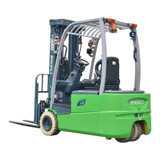
- Page 1 Operating and Service Manual EK18A-189LI / EK18A-212Li...
- Page 2 Foreword To meet the demand of the market, based on the absorption the advantage of battery forklift truck both at home and abroad, combined with the company to introduce advanced technology at home and abroad and the development of new products, our company developed the battery powered counterbalance forklift truck.
-
Page 3: Table Of Contents
CONTENTS I. Safety regulations for driving and operation of forklift truck ........1 1. Fundamental principle ..................1 2. The delivery of the truck ..................1 3. The storage of the truck ..................1 4. Preparations before use ..................1 5. -
Page 4: Safety Regulations For Driving And Operation Of Forklift Truck
I. Safety regulations for driving and operation of forklift truck 1. Fundamental principle Drivers and superiors of the truck should always keep “SAFTY FIRST” in mind. Operate according to the OPERATION & SERVICE MANUAL and OPERATOR’S MANUAL. 2. The delivery of the truck Pay attention to the following items when delivering the forklift truck by car: (1) Pull up the hand brake;... -
Page 5: Operation Of Forklift Truck
(6) Complete the preparation work before starting; (7) Loose the parking brake; (8) Carry out the operation of mast lifting and lowering, forward and backward tilting, steering and braking. 5. Operation of forklift truck (1) Only trained and authorized operator shall be permitted to operate the truck; (2) Wear safety guards such as shoes, helmet, clothing and gloves while operating the truck;... -
Page 6: Daily Maintenance Of Forklift Truck
(13) Tilt the mast backward as possible if the lifting height is high. Load or unload with mast slightly forward or backward tilt; (14) Slow down and be more careful when travelling on dock or bridge plate; (15) When checking the battery or fuel tank level the driver should not be on the truck and make the truck shut down and stop steadily;... - Page 7 Check parking brake function: when parking brake starts, stop on the ramp with specified slope (no load); Instruments and lighting fixtures, etc. : check whether all parts of instruments, lighting, connectors, switches and electrical lines work normally. (2) Oil and grease for the truck Name Original brand Mark, code and service temperature...
- Page 8 (3) The figure of Lubrication System...
-
Page 9: Primary Parameters Of Forklift Truck
". Primary Parameters of Forklift Truck... - Page 10 Primary Parameters Specialty Model code EK18A-LI Configuration GE1(2/6)LI Rated load weight lbs. 4000 Load center distance Inch Power source Battery Operation type Sit-on truck Tire Tire type Super elastic solid tire Size of front tire 200/50-10 Size of rear tire 16X6-8 Dimension parameter Angle of mast,...
- Page 11 Main detachable parts dimensions and weights Truck configuration EK18A-LI Unit GE1(2/6)LI Item Max external 485x230x370 dimension Drive axle Weight Max external 1060×611× dimension Counterweig Weight 1295 Max external 1550×950×1540 dimension Overhead guard Weight Max external M a s( t M300, 1010×420×2080 dimension excluding...
-
Page 12: რ. The Structure, Principle, Adjustment And Maintenance Of Forklift Truck
რ. The Structure, Principle, Adjustment and Maintenance of Forklift Truck 1. Transmission system 1.1 General description The drive system of this series of electric forklift adopts the drive unit produced by German ZF Company, which is left and right drive units and arranged symmetrically. - Page 13 Fig.1-2 Transport of drive axle Sling position 2.Wheel hub bolt 1.3.2 Storage of drive axle After the drive axle stored for 6 months, the starting motor works at approximately 1000rpm maintained for 2 minutes, so that the gear oil inside the drive axle is fully agitated and reactivated to ensure that each part is lubricated.
- Page 14 Fig.1-3 Position of each oil hole 1. Oil filling port of gear box 2. Oil drain hole of Gear box 1.3.4 The brake connection of the drive axle Fig.1-4 Position of brake oil port 1. Breathing cap connector 2. External braking hydraulic oil connector (M10X1) 3.
- Page 15 Incorrect connections may cause personal injury or damage to parts. Be sure to follow the electrical wiring diagram for proper connection. Maximum tightening torque of nuts on UVW binding posts is 8Nm. If connected according to the distribution of U, V and W, the rotation direction of the motor is clockwise (look from the input side of the motor).
- Page 16 Oil drainage a) Clean the area around the drain plug thoroughly; b) Place a suitable container under the drain plug to receive the oil; c) Remove the oil plug and seal ring with tools; d) Drain the old oil completely into the container. Refuel a) Clean the iron dust on the oil drain plug;...
- Page 17 Fig.1-6 The drive axle and external connection 1.Hub nut 2. Bolts M14x1.5x70...
-
Page 18: Braking System
2. Braking system 2.1 General description Service brake system is mainly hydraulic power brake, mainly by the brake pedal, brake pump, oil cup and wet brake composition, wet brake integrated in the drive axle. Parking brake adopts pedal brake, By stepping on the brake pedal, the cable drives the left and right brake sub-pumps to realize parking braking. - Page 19 Fig.2-2 Service brake device 2.3 Brake pedal adjustment (1) Shorten the push rod on the brake main pump; (2) Adjust the stop bolt. As shown in the figure below, adjust the pedal height, which is about 60-75-mm; After stepping the pedal, the gap between the pedal and the front bottom plate should be greater than 20 mm;...
- Page 20 2.4 Brake master pump The master pump consists of a seat, a one-way valve, a return spring, and a leather bowl, piston and auxiliary leather bowl. The ends are secured with stop washers and stop wire, the exterior is protected by a rubber dust cap, and the master pump piston is actuated by a push rod with the help of an operating brake pedal.
- Page 21 Fig.2-3 Brake master pump 2.5 The operation of parking brake Parking brake adopts pedal brake, by stepping on the brake pedal, drive the brake cable, through the brake lever plate is divided into two ways, respectively drive the left cable and right cable to drive the brake sub-pump action, so as to achieve parking brake.
- Page 22 Figure 2-5 Parking brake pedal layout The normal operation sequence of forklift travelling is as follows: in standby state, press down the parking brake pedal to reset it, the indicator light of instrument parking brake turns off, and then put the gear switch on forward or backward, press on the accelerator, and the forklift moves.
- Page 23 2.8 Adjustment of brake switch a) Release the lock nut of the brake switch after the height of the brake pedal is adjusted; b) Unplug the plug to separate the wires; c) Turn the switch to make the gap A=1mm; d) Confirm that the brake light should be on when the brake pedal is pressed.
-
Page 24: Steering System
3. Steering system 3.1 General description The function of forklift steering system is to change the direction of forklift or keep the forklift traveling straight. The performance of steering system is directly related to driving safety, operating efficiency and operator's labour intensity. According to the power source used for steering, the steering system can be divided into mechanical steering system (manual steering system) and power steering system. - Page 25 turning angle, the appropriate volume of pressure oil through pipeline passed on to the steering cylinder, cylinder realize the steering through steering trapezoidal mechanism push the steering wheel. The difference between the full hydraulic steering device and the hydraulic power steering device is that the full hydraulic steering device replaces the mechanical components such as the mechanical steering device and the longitudinal pull rod, and the full hydraulic steering device is connected with the steering cylinder by high pressure tubing.
- Page 26 a comfortable position for the operator. (2) Steering gear G3 series 1.5~2t adopts the cycloidal rotary valve type full hydraulic steering gear, which is a closed dynamic load steering gear. (see hydraulic system for details). (3) Steering transmission mechanism The mechanism that deflected the left and right wheels in a certain relationship by passing the power output of the steering gear through the oil cylinder and the steering mechanism is called the steering transmission mechanism, which is realized by the horizontal oil cylinder steering bridge component (see the relevant steering...
- Page 27 Fig. 3-5 Add grease and adjust preload (6) Gently knock the wheel hub with a wooden hammer, turn the wheel hub 3 to 4 circles by hand to ensure smooth rotation, and measure the rotational torque of the wheel valley, whose value is 2.94~7.8N.m (0.3~0.8 kgm); (7) When the rotational torque is higher than the specified value, it can be returned 1/6 circle and then measured the rotational torque;...
- Page 28 1200 hours; (3) Pay attention to check the working status of steering system during daily maintenance. When steering, the manual force acting on the steering wheel should be 6-20N; The difference of right and left steering force is no more than 5N; When the car travels in straight line at the maximum speed, there should be no obvious snake phenomenon.
- Page 29 Figure 3-2 steering axle 1) steering cylinder 2) pivoting support 3) support gear shaft 4) hub 5) hub cover 6) lock nut 7) washer 8) bearing 9)bearing 10)oil seal 11)axle 12) Angle potentiometer (1) Steering cylinder The steering cylinder is a double-acting cylinder, and the piston rod is equipped with teeth in the middle.
- Page 30 Figure 3-3 Steering cylinder The hub is installed on the wheel shaft with two tapered roller bearings, and the wheel is installed on the hub through the rim. The end of the hub is equipped with an oil seal to keep the grease in the hub and shaft cavity, and a nut is used to adjust the tightness of the bearing.
- Page 31 the force applied is proper and the steering power is smooth. (2) Check if the layout of hydraulic circuit is proper and the installation of left and right hoses is right. (3) Lift up the rear wheels and slowly turn the steering wheel right and left several times to limit position so as to exhaust air from the hydraulic pipeline and the steering cylinder.
-
Page 32: Electric System
4. Electric system 4.1 General description The standard configuration of the electric system of G3 series 1.5-2t front-drive three-wheel forklift trucks is an AC control system, which can realize a silent, high efficient, smooth and safe control of the truck. The electrical system is mainly composed of combined instrument, traction control system, lifting control system, lithium tank group, control switch and lighting device, wiring harness and so on. - Page 33 机械式 组合开关 起升 S模式 前倾 P模式 侧移 属具 起升调速 加速器开关 加速器信号 倾斜位移传感器 倾斜切断阀继电器 转向限速 NEVP л降电磁阀 起升高位开关 倒车继电器 Lift Height SW к位机 内置 к缓冲开关 内置 压力开关 к位机 Figure 4-1a Principle diagram of electric system...
- Page 34 Figure 4-1b Principle diagram of electric system (Curtis system)
- Page 35 Discharge relay COIL TRAC. RIGHT & LEFT SMART DISPLAY MASTER PUMP COMBIACE2 NEWGEN PREMIUM ACE2 NEWGEN 80V/300A 80V/230+230A Figure 4-1c Principle diagram of electric system (ZAPI system)
- Page 36 4.2 Instrument 1) Panel layout 1 Fig. 4-2 Panel layout of technology system ● The meaning of gear display is: D - Drive,R - Reverse,N - Neutral ● The speed mode value can be customized as required. The following types are available: ●...
- Page 37 ● Notification icon, reserved, customizable according to customer requirements. ● Network signal quality:empty – none,one grid – poor,two grids – middle, three grids – good, More than four grids – excellent ● – already connected to the cloud, Internet cloud connect:the icon appears the icon not appears –not connected to the cloud ●...
- Page 38 3401T-5002 The battery icon on the main interface of the table would be displayed in different colors according to the battery quantity. The battery quantity range is 0~100%. The specific meanings of battery icons are as follows: 20%~100%: green 10%~19%: yellow with flashing 0%~9%:red with flashing.
- Page 39 4.3.2 Electronic control assembly 1. Bottom plate 2. Driven AC controller 3. Drive AC controller 4. Pump AC controller 5. Fuse 6. Fuse 7. Contactor 8. OPS buzzer Figure 4-4 Electronic control system assay (technology system)
- Page 40 1. Bottom plate 2. Driven AC controller 3. Drive AC controller 4. Pump AC controller 5. Fuse 6. Fuse 7. Contactor 8. OPS buzzer(24 V) 9. 24V relay Figure 4-5 Electronic control system assay (Curtis system)
- Page 41 1. Electric control plate 2. Drive controller 3. Pump controller 4. Main contactor 5. SW200 bracket 6. Copper bar 1 7. Copper bar 2 8. Copper bar 3 9. Copper bar 4 10. Fuse holder 11. Fuse 12. OPS buzzer 13. Relay Figure 4-6 Electronic control system assay (ZAPI system)
- Page 42 Traction and pump motor controller (technology system) 1) The main control adopts 32-bit embedded integrated motor controller, working frequency 120MHz; 2) Advanced and efficient control algorithm to achieve constant torque and power control of AC induction motor; 3) Advanced PWM technology is adopted to realize efficient utilization of power supply voltage.
- Page 43 Drive and pump motor controller (Curtis System) 1 ) The use of vector control technology, combined with Curtis's algorithm, ensures that the controller always provides peak torque and optimal efficiency. 2) The torque and speed working area is very wide and the regeneration performance is perfect.
- Page 44 maximum allowable working temperature is 85ºC. ● Protection functions of ACE2 motor controller: a) Battery polarity protection b) Incorrect connection protection c) Over heat protection; overload protection; short circuit protection d) Protection class of controller 1P65 e)Out-of-control protection; f) Battery over discharging protection g)Mis-starting protection.
- Page 45 4.4 Motor Motor type: three phase AC type induction motor (free from maintenance) Table 4-1 Motor specification Pump motor Power 14KW Rated voltage Rated current 210A Rated speed 2337rpm Note In the inspection and maintenance of the motor must be operated without power, to avoid accidents.
- Page 46 (4) Lithium-ion batteries can be charged at any time, but it should be fully charged at least once a month in order to calibrate the battery level. It is recommended to fully charge the battery at least once a week during normal use (5) Do not flush the lithium battery with water to prevent the battery from water.
- Page 47 bolts on the power main circuit should be inspected. (5) Ensure that the low-voltage power supply of the truck is disconnected before maintenance, and then ensure that the truck is disconnected from the power loop of the battery system. Maintenance can be carried out after completion of the above confirmation.
- Page 48 safety valve without permission. (2) Be careful during the battery connection operation to avoid the phenomenon that the whole group or part of the battery is connected in reverse, or the whole group or part of the battery is short circuit. (3) In the process of taking the battery, it should be guaranteed that the battery is upright, Shall not be inverted.
- Page 49 (4) The storage environment should be kept dry and ventilated, away from heat source. :Notes (1) If the SOC of the battery system is lower than 20%, please charge it in time. (2) Please use the special charging equipment authorized by the manufacturer to charge.
- Page 50 normal. continue unchanged forklift works in lead-acid or growing mode. 2) battery cell performance test. 2) the consistency of the 3) replace the current sensor. battery cell. 4) Replace BMS. 3) the current sensor is damaged. 4) BMS fault. 1) Re-plug the EV Charger and connect the battery charger source.
- Page 51 use parking brake pedal, and the hand brake light lighting up constantly, the travelling function has been limited. When operate the truck again, the parking brake pedal must be step on again, the hand brake switch light is out, the travelling function limited is released, the work could be started.
- Page 52 Figure 4-7 Emergency power off switch Danger Do not turn off emergency power off switch when truck is travelling. in some cases, if turn off emergency switch suddenly, the goods would fall off from the fork, causes damage of people and goods. Only when forklift is travelling, if it is impossible to stop forklift by other ways, then turn off emergency power off switch manually.
- Page 53 Diagnostics can be provided in two ways: one is to use a digital handheld unit, which can provide detailed fault information; The other is that the fault codes are transmitted by CAN-BUS, and the fault codes and module nodes are displayed on the intelligent instrument.
- Page 54 to "Restore Factory Settings" operation 2. After executed solution 1, If the fault persists with powered on again, replace the control unit. 1. When power on, must start work after the main circuit breaker sucked. Driver bus low 2. Check that the coil control terminal of the main circuit breaker voltage alarm is properly connected to the main harness connection...
- Page 55 the battery is higher than the "battery reset value" after charging, can the fault code be eliminated and the electric control be allowed to work normally. 2. Measure the battery voltage. If the measured voltage is inconsistent with the battery discharge protection value, replace the control unit.
- Page 56 2. If the heat dissipation measures of the above modules are all good, it is necessary to check whether the drive motor works normally. If it does not work properly, the power module will overheat. Second, replace the power module. 3.Replace the control unit.
- Page 57 3.Replace the control unit. The output of the 1. Check whether the U, V, and W power cables of the motor are drive power unit connected reliably. default phase 2. Replace the driver module. Battery pack is low 1. Check the battery connection voltage, output 2.
- Page 58 3. Replace the controller. 1. Check whether the output port is overloaded. HP_OUT5 output 2. Check whether the corresponding output port connection port overcurrent wiring harness is short circuit. 3. Replace the controller. 1. Check whether the output port is overloaded. DO6 output port 2.
- Page 59 there is brake lock or other abnormal conditions. 1. Check the direction switch. Direction switch 2. Check the related wiring harness. failure 3. Replace the control unit. 1. Check whether the seat switch is connected incorrectly or The seat switch is not damaged.
- Page 60 ISO solenoid valve 1. Check the load. control port output 2. Check the connection wire. overcurrent 3. Replace the control unit. The output current of 1. Check the load. the fan control port is 2. Check the connection wire. overcurrent 3.
- Page 61 1. Check the value setting of "Accelerator pedal Calibration" to see whether the minimum and maximum voltage values of the accelerator pedal are set accurately. If not, recalibrate the accelerator pedal and set it with the monitoring software of the upper computer.
- Page 62 Lithium battery pack overtemperature Check lithium battery pack. protection Lithium battery pack Check lithium battery pack. total voltage high Lithium battery pack Check lithium battery pack. overcurrent Lithium battery pack Check lithium battery pack. cut-out protection Lithium battery pack Check lithium battery pack. charging connect Lithium battery pack Check lithium battery pack.
- Page 63 Communication 1. Check the communication wire harness between the dual between dual-drive drives; modules is 2. Check the module parameters "drive motor type" setting is interrupted correct; (2) Common faults of pump control system Fault Fault name Details code 1. The fault may be caused by inefficient heat dissipation. Check the heat dissipation between the power module and the aluminum plate and between the aluminum plate and the frame.
- Page 64 power unit is between the oil pump module and the motor is short-circuited unsaturated or (short-circuited between three-phase cables or short-circuited overcurrent between a phase cable and the frame), and check whether the motor coil has a burning smell. 2. Check the cable connection of the control unit and the oil pump module is normal connection (only V series products).
- Page 65 unit one by one. 3. Replace the control unit. 1. Check whether the 5V output is grounded, and check whether 5V voltage output the wiring of each motor encoder is correct. fault of oil pump 2. Exclude external devices that use 5V output from the control control unit unit one by one.
- Page 66 working for a long time because the multi-way valve joystick potentiometer or switch signal cannot be reset normally. The oil pump electricity working for a long time would lead to its very high temperature. 1. The fault may be caused by inefficient heat dissipation. Check the heat dissipation between the power module and the aluminum plate and between the aluminum plate and the truck frame.
- Page 67 2. Replace the lifting potentiometer 3. Replace the control unit. 1. Check whether the wire harness between the temperature Oil pump motor sensor of the oil pump motor and the main cable is normal. temperature sensor 2. Replace the oil pump motor temperature sensor. short circuit failure 3.
- Page 68 extreme environment. temperature below +95°C, Excessive load on vehicle. and cycle interlock or KSI. Improper mounting controller. Battery parameters misadjusted. Set: Capacitor bank voltage Non-controller system drain on dropped below the Severe battery. Undervoltage limit with Severe Battery resistance too high. FET bridge enabled.
- Page 69 Battery parameters voltage below misadjusted. Overvoltage limit. Battery resistance too high for given regen current. Battery disconnected while regen braking. Set: +5V supply (pin 26) 5V Supply External load impedance on the outside the 5 V±10% range. Failure +5V supply (pin 26) is too low. Clear: Bring voltage within range.
- Page 70 Set: Driver 1 (pin 6) is either open or shorted. This Open or short on driver load. Coil 1 Driver fault can be set only when Dirty connector pins. Open/Short Main Enable = Off. Bad crimps or faulty wiring. Clear: Correct open or short, and cycle driver.
- Page 71 Main contactor tips are welded Set: Just prior to the main closed. contactor closing, Motor phase U or V capacitor bank voltage (B+ disconnected or open. connection terminal) was Main Contactor Welded An alternate voltage path (such loaded for a short time and as an external pre-charge resistor) is voltage providing a current to the capacitor...
- Page 72 Set: Pot2 wiper (pin 17) voltage is lower than the low fault threshold (can be changed with Pot2 Wiper Low Pot2 wiper voltage too low. function Setup_Pot_Faults()). Clear: Bring Pot2 wiper voltage above the fault threshold. Set: (pin current exceeds 10 mA. Pot Low Combined resistance...
- Page 73 so that the vehicle will not operate requires cycling of KSI. until KSI is cycled. For example, if a Clear: Cycle KSI. user changes the Throttle Type this fault will appear and require cycling KSI before the vehicle can operate. Set: the error of GPS GPS ID...
- Page 74 Driven Standby Pump Standby Drive Standby Driven Standby Pump Set: Received GPS Lock Grade 1. Received the GPS Grade 1 truck Grade 1 truck lock signal Drive lock signal Clear: GPS cancel the lock the truck Standby Driven Standby Pump Set: controller overheating in the receiving...
- Page 75 Set: Travelling instrument communication Unmatched 1. Startup travelling and instrument failed Drive Display handshake failure Clear: Check the CAN communication between travelling and instrument Standby Driven Standby Pump Set: The controller received transfer current BMS current 1. Received the current limiting limiting information Drive limit...
- Page 76 message. a long time. Clear: Check the CAN communication between travelling and BMS. Standby Driven Standby Pump Set: battery 1. Received undervoltage signal undervoltage alarm Drive Undervoltage from BMS Clear: Check the battery Standby Driven Standby Pump Set: Runtime VCL code error condition.
- Page 77 Period. Clear: Cycle KSI or receive CAN NMT message. Set: No motor encoder movement detected. Clear: Either cycle KSI, or 1. Stalled motor. if parameter LOS Upon 2. Motor encoder failure. Encoder Fault = On and Stall Detected 3. Bad crimps or faulty wiring. Interlock has been cycled, 4.
- Page 78 voltage supply for the driver circuits. detection. Clear: Cycle KSI. 1. Motor characterization failed during characterization process. 0 = sequencing error. Normally caused turning Motor Characterization Test Enable before running the test. 1 = encoder signal seen but step size not auto-detected;...
- Page 79 fault is issued when they do not. Clear: Download the correct VCL and OS software into the controller. Set: After the EM Brake was commanded to set and time has elapsed to allow 1. Vehicle movement sensed after the the brake to fully engage, EM Brake has been commanded to EM Brake Failed vehicle movement has been...
- Page 80 Clear: Download appropriate software your controller model. Set: When the Dual Drive software is enabled, the controller must be set to either Speed Mode Express or Speed Mode; otherwise this fault is set. 1. Dual drive enabled on only one controller.
- Page 81 undervoltage condition at the key input . Undervoltage threshold is 11V for 36/48V controllers and 30 V for 80V controllers. Troubleshooting (fault at startup or in standby) - Fault can be caused by a key input signal characterized by pulses below the undervoltage threshold, possibly due to external loads like DC/DC converters starting-up, relays or contactors during switching periods, solenoids energizing or de-energizing.
- Page 82 positive rail value. If one phase voltage is lower than a certain percentage of the rail voltage, this alarm occurs. Cause 2 Motor running test. When the motor is running, the power bridge is on and the motor voltage feedback tested; if it is lower than expected value (a range of values is considered), the controller enters in fault state.
- Page 83 It is suggested to verify the power contacts of LC; if they are stuck, is necessary to replace the LC. Cause The LC coil is driven by the controller, but it seems that the power contacts do not close. In order to detect this condition the controller injects a DC current into the motor and checks the voltage on power capacitor.
- Page 84 power section. Replace the controller. Cause: The temperature of the controller base plate is above 85 °C. The maximum current is proportionally decreased with the temperature excess from 85 °C up to 105 °C. At 105°C the current is limited to 0 A. Troubleshooting: It is necessary to improve the controller cooling.
- Page 85 Check if there is a short or a low impedance pull-down between NLC and –BATT. - The driver circuit is damaged; replace the logic board. Cause The LC coil driver is not able to drive the load. The device itself or its driver circuit is damaged.
- Page 86 - Ask for help to a EKKO technician. Cause: the traction parameter "DISP TYPE" was wrong WAIT DISP AUTH Troubleshooting: Check the parameter. Cause: the display is disconnected NO CAN DISP Troubleshooting: Check the wiring, or ask for help to a Zapi technician.
- Page 87 when this alarm appears , traction speed will reduce to 50% of the maximum speed and traction max current also will be reduced to 50% of the maximum current, pump current also will be reduced to 50% of maximum current , tilt and steering function can work as normal .
- Page 88 manufacturer ,or set traction parameter "NETWORKING" to "OFF" (in set options menu). cause Networking alarm ; the traction inverter received the 1AA message from the networking device, if the inverter lost this message, this alarm will appears, the truck should inhibit lifting and traction function , but tilt , side shift , attachment , steering function can work as normal 0X1AA TIMEOUT...
- Page 89 Cause: Lithium battery alarm ; the traction inverter lost the 2F0 message, and the inverter can't receive this message again within 2F0 TIMEOUT 800ms , when this alarm will appears, truck should stop work , inhibit traction and lifting and tilt , only steering function can work as normal Troubleshooting: Check the lithium battery, recycle the switch ,or ask for help to the lithium battery manufacturer...
- Page 90 SP MISMATCH XX (1) Checks the correspondence of the parameters between Master and Supervisor (2) Ask for assistance to a EKKO technician (3) If the problem is not solved it is necessary to replace the logic board REMA T. ALARM This alarm isn't used for this truck.
- Page 91 Troubleshooting BUMPER STOP Turn off one or both inputs dedicated to the bumper functionality. If the alarm occurs even if the inputs are in the rest position, check if the microswitches are stuck. In case the problem is not solved, replace the logic board The control detects a mismatch between the expected slip and the ED SLIP MISMATCH evaluated...
- Page 92 Cause: If DC Pump option is set to ON, the software expects the voltage on -P output to be at a “steady state” value, before switching the LC on. WAIT MOTOR STILL If the voltage is different, it could be due to the fact that the motor connected to -P is not still.
- Page 93 Troubleshooting - Check the connections between the controller outputs and the loads. - Collect information about characteristics of the coil connected COIL SHOR. EB. to the driver and ask for assistance to a Zapi technician in order to verify that the maximum current that can be supplied by the hardware is not exceeded.
- Page 94 Cause: Input mismatch between Hard & Soft input and tiller input : the two inputs are activated at the same time. Troubleshooting: - Check if there is wrong connection in the external wiring. - Using the “Tester” menu of the controller verify that what the TILLER ERROR controller sees in input is in accordance with the actual state of the external switch inputs.
- Page 95 Troubleshooting: - Check wirings. PUMP INC START - Check microswitches for failures. - Through the TESTER function, check the states of the inputs are coherent with microswitches states. - If the problem is not solved, replace the logic board. Cause: Switching the LC on, the software checks the output voltage on -P connector, and expects that it is at a “steady state”...
- Page 96 Troubleshooting: - Verify that the EB coil is connected correctly . - Verify that the parameter POSITIVE E.B.is set in accordance SMART DRIVER KO with the actual configuration . The software, in fact, depending on specific parameter value, makes a proper diagnosis; a wrong configuration of this parameter could generate a false fault.
- Page 97 Cause Short circuit between two motor phases. The number that follows the alarm identifies where the short circuit is located: - 36 à U – V short circuit - 37 à U – W short circuit - 38 à V – W short circuit MOT.PHASE Troubleshooting (36/37/38)
- Page 98 Cause This fault is displayed when the controller detects an overvoltage condition. Overvoltage threshold is 65 V for 36/48V controllers and 116 V for 80V controllers. As soon as the fault occurs, power bridge and MC are opened. The condition is triggered using the same HW interrupt used for undervoltage detection, uC discerns between the two VDC LINK OVERV.
- Page 99 Troubleshooting INIT VMN LOW - Check the motor power cables. - Check the impedance between U, V and W terminals and -Batt terminal of the controller. - Check the motor leakage to truck frame. - If the motor connections are OK and there are no external low impedance paths, the problem is inside the controller.
- Page 100 Cause The error between the power setpoint and the estimated power is out of range. POWER MISMATCH Troubleshooting Ask for assistance to a Zapi technician about the correct adjustment of the motor parameters. Cause The voltage feedback of LC driver is different than expected Troubleshooting - Verify that the coil is connected correctly.
- Page 101 Cause: The output of the motor thermal sensor is out of range. Troubleshooting: SENS MOT TEMP KO Check if the resistance of the sensor is what expected measuring its resistance. - Check the wiring. - If the problem is not solved, replace the logic board. Cause: The voltage of traction A24 pin is wrong, A24 pin voltage is +80V, from the key, if the voltage is wrong, this alarm will...
- Page 102 Cause: The controller receives from the CAN bus the message that another controller in the net is in fault condition; as a consequence the controller itself cannot enter into an operative WAITING FOR NODE status, but it has to wait until the other node comes out from the fault status.
- Page 103 Cause This fault appears when no load is connected between the NLC output and the positive voltage (for example +KEY). Troubleshooting LC COIL OPEN - Check the wiring, in order to verify if LC coil is connected to the right connector pin and if it is not interrupted. - If the alarm is still present, than the problem is inside the logic board;...
- Page 104 Cause: The maximum current gain parameters are at the default values, which means the maximum current adjustment procedure has not been carried out yet. CURRENT GAIN Troubleshooting: Ask for assistance to a Zapi technician in order to do the adjustment procedure of the current gain parameters. Cause This alarm occurs when the A/D conversion of the analog inputs returns frozen values, on all the converted signals, for more than...
- Page 105 Troubleshooting: - Check the EVs conditions. COIL SHOR. EVAUX - Check the wiring. - Collect information about characteristics of EV coils and ask assistance to a Zapi technician. - If the problem is not solved, replace the logic board. Cause: This fault appears when no load is connected between the NAUX1 output and the positive terminal PCOM .
- Page 106 Troubleshooting: This alarm could be caused by a CAN bus malfunctioning, which blinds master- supervisor communication Cause: This is a warning to point out that it is time for the programmed maintenance. CHECK UP NEEDED Troubleshooting: Turn on the CHECK UP DONE option after that the maintenance service.
- Page 107 ○ Pump master CPU fault ALARM ALARMS OF NODE 5.0 CODE Cause: This is a safety related test. It is a self-diagnosis test that involves the logic between master and supervisor microcontrollers WATCHDOG Troubleshooting: This alarm could be caused by a CAN bus malfunctioning, which blinds master-supervisor communication Cause A hardware problem in the logic board due to high currents (overload).
- Page 108 Troubleshooting: A) If the problem occurs at start up (the LC does not close at all), check: - Motor internal connections; - Motor power cables connections; If the motor connection are OK, the problem is inside the controller. B) If the problem occurs after closing the LC (the LC closes and then PUMP VMN opens back again), check: - Motor internal connections;...
- Page 109 Cause 1 Before switching the LC on, the software checks the power bridge: it turns on alternatively the low-side power MOSFETs and expects the phase voltages decrease down to -B. If the phase voltages are higher than a certain percentage of the nominal battery voltage, this alarm occurs.
- Page 110 Troubleshooting: - Check the motor connection, that there is continuity. If the motor PUMP I=0 connection is opened, the current cannot flow, so the test fails and the EVER error code is displayed; - If everything is ok for what it concerns the motor, the problem could be in the current sensor or in the related circuit.
- Page 111 Cause: This warning occurs when the temperature sensor is open (if digital) or if it has overtaken the MAX MOTOR TEMP threshold (if analog) Troubleshooting: - Check the temperature read by the thermal sensor inside the motor MOTOR through the MOTOR TEMPERATURE reading in the TESTER TEMPERAT.
- Page 112 - If the problem is still present after replacing the encoder, the failure is in the controller. This is not implemented in DUALACE2. PEDAL WIRE Troubleshooting: - Ask for help to a EKKO technician. Cause: This is a warning the tilt linear pot. is doing the acquisition...
- Page 113 TILT LIN Troubleshooting: ACQUIS. Once the acquisition is done. re-cycle the key, then this alarm will disappear Cause: TILT LIN OUT Th input of tilt linear pot. is not in the acquired range Troubleshooting: Acquire the maximum and minimum potentiometer values through pump "ADJUSTMENT "menu.
- Page 114 Cause: The TILT POT. input read by the microcontroller is not comprised in the range "MIN TILT UP" ÷ "MAX TILT UP" (or "MIN TILT DOWN" ÷ "MAX TILT DOWN") TILT POT Troubleshooting OUTRNG Acquire the maximum and minimum TILT potentiometer value through the pump "ADJUSTMENT"...
- Page 115 Troubleshooting Acquire the maximum and minimum Aux. potentiometer value OUTRNG through the pump "ADJUSTMENT" menu. If the alarm is still present, check the mechanical calibration and the functionality of the potentiometer. If the alarm is not disappeared the failure is in the controller logic board, replace it.
- Page 116 1ST LEV This alarm is not implemented in pump. INHIBIT AUTH. FAILED This alarm is not implemented in pump. 0X1AA This alarm is not implemented in pump. TIMEOUT REM DEV INIT This alarm is not implemented in pump. Cause: “SET MOTOR TEMP.” Parameter out of range (-20, +20), WR.
- Page 117 Cause: RPM HIGH This alarm occurs in Gen. Set versions when the speed exceeds the threshold speed. Cause The two digital inputs dedicated to the bumper functionality are high at the same time. Troubleshooting BUMPER STOP - Turn off one or both inputs dedicated to the bumper functionality; - If the alarm occurs even if the inputs are in the rest position, check if the microswitches are stuck.
- Page 118 Cause: This alarm occurs only when the controller is configured as PMSM and the feedback sensor selected is sin/cos. The signal coming from sin/cos sensor has a wrong direction. The hexadecimal value “XX” SIN/COS facilitates Zapi technicians debugging the problem D.ERR.XX Troubleshooting: Check the wirings.
- Page 119 Cause The controller detected a difference between the estimated absolute orientation of the rotor and the position of the index signal (ABI encoder). HOME SNES. ERR XX It is caused by a wrong acquisition of the angle offset between the orientation of the rotor and the index signal Troubleshooting Repeat the auto-teaching procedure.
- Page 120 Troubleshooting Reset the alarm by switching key off and on again. If the alarm OVERLOAD condition occurs again, ask for assistance to a Zapi technician. The fault condition could be affected by wrong adjustments of motor parameters. Cause “ENCODER 1” parameter Mismatch between PULSES...
- Page 121 Troubleshooting: - Check if there is wrong connection in the external wiring. - Using the “Tester” menu of the controller verify that what the TILLER ERROR controller sees in input is in accordance with the actual state of the external switch inputs. - Check if there is short circuit between A6 and A1 - In case no failures/problems have been found, the problem is in the controller, which has to be replaced.
- Page 122 Troubleshooting: - Check wirings. PUMP INC - Check microswitches for failures. START - Through the TESTER function, check the states of the inputs are coherent with microswitches states. - If the problem is not solved, replace the logic board. Cause: Switching the LC on, the software checks the output voltage on -P connector, and expects that it is at a “steady state”...
- Page 123 Troubleshooting: - Verify that the EB coil is connected correctly . - Verify that the parameter POSITIVE E.B.is set in accordance with SMART the actual configuration . The software, in fact, depending on specific DRIVER KO parameter value, makes a proper diagnosis; a wrong configuration of this parameter could generate a false fault.
- Page 124 Cause Short circuit between two motor phases. The number that follows the alarm identifies where the short circuit is located: - 36 à U – V short circuit - 37 à U – W short circuit - 38 à V – W short circuit MOT.PHASE Troubleshooting SH.
- Page 125 116 V for 80V controllers. As soon as the fault occurs, power bridge and MC are opened. The condition is triggered using the same HW interrupt used for undervoltage detection, uC discerns between the two evaluating the voltage present across DC-link capacitors: - High voltage à...
- Page 126 Troubleshooting - Check the motor power cables. - Check the impedance between U, V and W terminals and -Batt terminal of the controller. - Check the motor leakage to truck frame. - If the motor connections are OK and there are no external low impedance paths, the problem is inside the controller.
- Page 127 Cause The error between the power setpoint and the estimated power is out of POWER range. MISMATCH Troubleshooting Ask for assistance to a Zapi technician about the correct adjustment of the motor parameters. Cause The voltage feedback of LC driver is different from expected, i.e. it is not in accordance with the driver operation.
- Page 128 the main contactor). Cause: The output of the motor thermal sensor is out of range. Troubleshooting: SENS MOT - Check if the resistance of the sensor is what expected measuring its TEMP KO resistance. - Check the wiring. - If the problem is not solved, replace the logic board. Cause: The voltage of A17 pin is wrong, if the voltage is wrong, this alarm...
- Page 129 Check the connections between the controller outputs and the loads. - Collect information about characteristics of the coil connected to the driver and ask for assistance to a Zapi technician in order to verify that the maximum current that can be supplied by the hardware is not exceeded.
- Page 130 is found to be faulty. The hexadecimal value “XX” EB driver facilitates Zapi technicians debugging the problem. Troubleshooting: This type of fault is not related to external components. Replace the logic board. Cause This fault appears when no load is connected between the NLC output and the positive voltage (for example +KEY).
- Page 131 Cause This alarm occurs when the A/D conversion of the analog inputs returns frozen values, on all the converted signals, for more than 400 ms. The goal of this diagnosis is to detect a failure in the A/D ANALOG converter or a problem in the code flow that skips the refresh of the INPUT analog signal conversion.
- Page 132 output and the positive terminal PCOM . Troubleshooting: - Check the EB coil. - Check the wiring. - If the problem is not solved, replace the logic board. Cause: A wrong profile has been set in the throttle profile. THROTTLE PROG.
- Page 133 SENS. KO The output of the controller thermal sensor is out of range. Troubleshooting: This kind of fault is not related to external components. Replace the controller. Cause At start-up, the controller checks the battery voltage (measured at key input) and it verifies that it is within a range of ±20% around the nominal value.
- Page 134 Cause: This is a safety related test. It is a self-diagnosis test that involves the logic between master and supervisor microcontrollers WATCHDOG Troubleshooting: This alarm could be caused by a CAN bus malfunctioning, which blinds master-supervisor communication Cause An hardware problem in the logic board due to high currents (overload).
- Page 135 VOLT, programmed through the STEER ACQUIRING function . Troubleshooting: Acquire the maximum and minimum values from the steering potentiometer through the STEER ACQUIRING function. Check the mechanical calibration and the functionality of the potentiometer. - If the problem is not solved, replace the logic board. Cause “ENCODER 1”...
- Page 136 performed, replace the controller. Cause The algorithm implemented to check the main RAM registers finds wrong contents: the register is “dirty”. This alarm inhibits the machine WRONG RAM operations. MEM. Troubleshooting Try to switch the key off and then on again, if the alarm is still present replace the logic board.
- Page 137 Cause This alarm occurs when a mismatch is detected between the setpoint CTRAP for the overcurrent detection circuit (dependent on parameter DUTY PWM CTRAP) and the feedback of the actual threshold value. THRESHOLD Troubleshooting The failure lies in the controller hardware. Replace the logic board. Cause This alarm occurs when the A/D conversion of the analog inputs returns frozen values, on all the converted signals, for more than 400...
- Page 138 Cause: This is a safety related test. The master μC has detected a supervisor μC wrong set point. SP MISMATCH Troubleshooting: Check the matching of the parameters between master and supervisor. - Ask for assistance to a Zapi technician. - If the problem is not solved, replace the logic board. Cause CANbus communication does not work properly.
- Page 139 a travel demand Troubleshooting: The typical root cause for this error code to be displayed is in the harness or in the load coil. So the very first check to carry out concerns connections between dashboard outputs and loads. In case no failures/problems have been found externally, the problem is in the logic card, which has to be replaced Cause:...
-
Page 140: Hydraulic System
5. Hydraulic system 5.1 General description The hydraulic system is composed of oil pump, multi-way valve, priority valve, lifting oil cylinder, tilting oil cylinder, high and low pressure oil pipe, joint and other parts. The lifting motor drives the oil pump, which converts mechanical energy into hydraulic energy and supplies the system with oil, which is distributed to each cylinder through multiple valves. - Page 141 atmospheric pressure, and fills between the teeth. The volume of the space represented by the number 2 (where the gear enters the engagement) decreases from large to small, and the oil is hydraulic into the pressure oil path. Namely 1 is oil suction cavity, 2 is pressure oil cavity, they are separated by the meshing point of two gears.
- Page 142 (1) pump body (2) drive gear (3) passive gear (4) front end cover (5) rear end cover (6) liner plate (7) sealing ring (8) retaining ring (9) oil seal (10) elastic retaining ring 5.1.2 Multiway valve The multiway valve appearance is shown in Fig.5-3. Fig.5-3 Outline drawing of multiple valve The multi-way valve adopts two pieces of four-type, the hydraulic oil from the working oil pump is controlled by the multi-way valve stem, and the high-pressure oil...
- Page 143 a connecting shaft, the shaft is fixed on the front valve connecting plate of the frame through the bracket, the joystick operates the multi-way valve through the connecting rod. The multi-way valve mounting bracket is provided with a trigger pull rod and a micro switch.
- Page 144 Fig. 5-5 Multi-way valve control handle identification According to the direction of the arrow shown in figure 5-5, push forward and pull back the lifting handle, the mAst will rise and fall, push forward and pull back the tilting handle, and the mast will tilt forward and backward. (2) Limit solenoid valve One end of the limit solenoid valve is connected with the oil outlet of the multi-way valve tilting valve plate, and the other end is connected with the tilting steel...
- Page 145 a) Unscrew the measuring hole screw plug of the inlet part of the multi-way valve, and install an oil pressure gauge that can measure 25MPa. b) Operate the tilting handle to measure the pressure at the bottom of the cylinder stroke.
- Page 146 the mast is raised, the high-pressure pipe rupture can be a safety protection. 1.Bolt M16×1.5×40 2.Gasket 16 3.Chain wheel 4.Retainer ring 40 5.Chain assy’ 6.Sleeve 7.Bolt M12×1.25×25 8.Bolt M12×1.25×50 9.U bolt 10.Nut M10×1.25 11.Gasket 10 12.Gasket 10 13.Pin B10×26 14.Adjusting block 15.Cylinder support block 16.Nut M12×1.25 17.Piston rod 18.Scraper seal 40×52×7/10 19.Guide sleeve 20.Seal ring 40×50×6 21.Steel-backed bearing 4030...
- Page 147 the A hole on the outer circumference of the valve core. If the flow rate of the oil through the hole is less than the set value of the valve, the pressure difference before and after the valve core is less than the spring force, then the valve core does not move and the slide valve does not act.
- Page 148 difference, and open the ball valve (item 8), when the pressure difference exceeds the spring force of spring 2, 7 to the right valve core, the oil flow rate due to the smaller of D, C, This reduces the flow through the throttle orifice. Fig.5-10 The speed limit valve (1) Speed Limit Valve connector (2) spring...
- Page 149 the bottom of the oil cylinder, thus pushing the piston forward to make the mast tilt forward; When the slide valve is pulled back, the high-pressure oil enters from the front of the cylinder block, pushing the piston backwards until the mast tilts back into place.
- Page 150 Fig. 5-12 Schematic diagram of hydraulic system (1) Hydraulic oil tank (2) Oil suction filter (3) Pump motor (4) Gear pump (5) Multi-way valve (6) Steering gear (7) Steering cylinder (8) Speed Limit Valve (9) Stop valve (10) Lifting cylinder (11) Tilt cylinder (12) Attachment cylinder (13) Return oil filter...
- Page 151 5.2 Maintenance, fault analysis and troubleshooting methods 5.2.1 Maintenance Before and after the shift, check whether there is leakage or serious oil leakage in the pipe joint, lifting cylinder, tilting cylinder, oil pump, full hydraulic steering gear and steering cylinder of the hydraulic transmission system; Check whether there is enough working oil in the working tank;...
- Page 152 amount of articulated joint and tighten the joint slide bolt. 1) Leakage caused by wear of the sealing Replace seal ring. ring at the fastener. 2) The hydraulic oil is foaming after Remove air and replenish hydraulic mixed with air, and the suction pipe is fluid.
-
Page 153: Lifting System
6. Lifting system 6.1 General description of basic type lifting system The lifting system is of the two-stage roller type with vertical up and down. It consists of the inner mast, the outer mast, two rear lifting cylinder, fork carrier, etc. 6.1.1 Inner and outer mast The inner and outer portal frames are welded parts, the weight is mainly supported on the truck frame, and the whole outer mast is mounted on front axle of... - Page 154 6.1.2 Fork carrier The fork carrier rolls through the main roller inside the inner mast. The main roller is mounted on the main roller shaft and stuck with elastic retaining ring. The middle and bottom rollers adopt compound rollers; The main roller shaft is welded to the fork carrier, and the side roller of the plate is bolted to the fork carrier.
- Page 155 6.1.3 Adjustment method of roller 8 compound rollers, respectively installed on the upper end of the outer mast (2), the lower end of the inner mast (2), and both sides of lower end and middle of the fork carrier (4); Two main rollers are mounted on the upper end of the column plate of the fork carrier.
- Page 156 Note: The clearance adjustment method of the side roller of the compound roller is as shown in the figure. Special gaskets are added between the side roller and the roller shaft. 6.1.4 Repair Adjusting of the lifting cylinder Readjust the stroke of the lift cylinder when the lift cylinder, the inner mast or the outer mast is replaced.
- Page 157 Fig.6-5 Adjustment of fork carrier height (a) Park the truck on a level ground and ensure the mast is vertical. (b) Make the bottom of the fork touch the ground, adjust the adjusting nut of the upper end joint of the chain so that there is an A distance(24~28mm) between the main roller and the mast channel, as shown in the Fig.6-6.
- Page 158 (c) Take down the connector on top of the chains. And take out chains from chain wheel. (d) Make the inner mast rise. (e) The forklift can be reversed when the fork carrier disengaged from the outer mast. (f) Replacing main rollers: ●...
- Page 159 (e) Take apart bolts which jointed lift cylinders and the bottom of outer mast and take apart the oil-pipe between two lift cylinders without loosing the nipple. (f) Lay down the inner mast and remove the main roller at the bottom of the inner mast.
- Page 160 Fig. 6-7 Inner and outer mast 6.2.2 Fork carrier The fork carrier rolls through the compound roller, the main and side rollers inside the inner mast. The main roller at the upper end of the column plate is mounted on the main roller shaft and stuck with the elastic retaining ring. The main roller shaft is welded to the fork carrier, and the side roller of the column plate is bolted to the fork carrier.
- Page 161 1. Limit screw 2. Washer 3. Load-backrest 4. Washer 5. Bolt 6. Fork carrier 7. Main roller 8. Retainer ring 9. Compound roller 10. Adjusting gasket 11. Side roller 12. Washer 13. Bolt 14. Fork assembly Fig. 6-8 Fork carrier 6.2.3 Adjustment method of roller As described in 6.1.3.
- Page 162 is not in sync; Add and subtract gaskets at the top of piston rod to synchronize the travel; An adjustment pad shall be added between the piston rod head and the beam of inner mast, and the thickness of the adjustment pad shall be 0.5mm and 1mm. (c) Adjust the tension of the chain.
- Page 163 (d) Lift the inner mast. (e) Take out the fork after confirming that the fork has been independent of the inner mast. (f) Replace main roller: ● Remove all spring collars and remove the main roller with a drawing tool, keep the adjustment pad.
- Page 164 (f) Lower the inner mast and remove the main roller at the bottom of the inner mast. (g) The main roller on the outer mast will also be exposed from the top of the inner mast, then remove the main roller. (h) Replace the main roller: ●...
- Page 165 Fig. 6-13 Inner, middle and outer masts 6.3.2 Fork carrier The fork carrier rolls through the compound roller, the main and side rollers inside the inner mast, the main roller at the upper end of the fork carrier is mounted on the main roller shaft and stuck with the elastic retaining ring.
- Page 166 1. Limit screw 2. Washer 3. Load-backrest 4. Washer 5. Bolt 6. Fork carrier 7. Main roller 8. Retainer ring 9. Compound roller 10. Adjusting gasket 11. Side roller 12. Washer 13. Bolt 14. Fork assembly Fig. 6-14 Fork carrier 6.3.3 Adjustment method for roller 12 compound rollers, respectively installed on the upper end of the outer mast (2), the upper end of the middle mast (2), the lower end of the middle mast (2), the lower...
- Page 167 Fig. 6-15 Roller layout Note :(a) Adjust the clearance of side rollers to be 0 ~ 0.5mm; (b) Butter the main roller surface and the contact surface of the mast. (Note: The maintenance of the upper compound roller of the inner, middle and outer mast belongs to the high maintenance, safety shall be paid attention to.
- Page 168 6.3.4 Repair Adjusting of the lifting cylinder When the lifting cylinder, inner mast or outer mast are removed and replaced, the stroke of the rear lifting cylinder shall be adjusted again (Note: there is no need to carry out the front lifting cylinder). See Fig. 6-17. Adjustment methods are as follows: (a) Install the piston rod head into the cylinder support of the middle mast without adjusting pad.
- Page 169 (2) Adjust the height of the fork carrier The same as described in 6.2.4 (2). (3) Replace the roller of fork carrier The same as described in 6.2.4 (3). (4) Replace the roller of mast (a) Remove the fork carrier from the inner mast in the same manner to replace the roller of mast as described in the 6.2.4 (3).
- Page 170 EKKO Material Handling Equipment Mfg., Inc. 1761 W Holt Ave Pomona, CA 91768 (877)232-6517 Info@ekkolifts.com Support@ekkolifts.com www.EKKOlifts.com...
Need help?
Do you have a question about the EK18A-189LI and is the answer not in the manual?
Questions and answers