
Related Manuals for EKKO EK16A-177


Summary of Contents for EKKO EK16A-177
- Page 1 Operations & Maintenance Manual Three Wheel Forklift EK16A-177/EK16A-138/EK16A-189LI...
- Page 2 Warning Before using this equipment, first pay attention to the following matters: ➢ Please read this manual carefully and operate the vehicle safely. ➢ Do not operate this vehicle without training. ➢ Please comply with ISO3691 "Safety Specification for Motor Vehicles Industry". ➢...
-
Page 3: Warning
FORWORD Our company’s balanced electronic forklift is developed from both domestic and international designs, integrating advanced production capabilities with innovative features created by our R&D department. These forklifts are ideal for handling and stacking packaged goods in various environments, including stations, ports, and warehouses, and are widely used in the food and textile industries. -
Page 4: Table Of Contents
Table of Contents Warning…………………………………………………………………………………………………………..1 Forward…………………………………………………………………………………………………………..2 Driving, Operation, and Daily Maintenance of the Forklift……………………………………………………..5 1. Transportation of the forklift…………………………………………………………………………….5 2. Forklift storage……………………………………………………………...…………………………...5 3. Preparation before work………………………………………………………………………..………..5 4. Operation instructions…………………………………………………………………………………...5 5. Battery charging…………………………………………………………………………………………7 6. Lubrication system…………………………………………………………………….………………...7 Construction, Principle, Adjustment and Maintenance of Forklift………………………………………………10 1. - Page 5 9. Maintenance of lift pump………………………………………………………………………………36 10. Troubleshooting………………………………………………………………………………………..40 Lifting System…………………………………………………………………………………………………..42 1. General Description……………………………………………………………………………………42 2. Inner and outer masts…………………………………………………………………………………..42 3. Lift bracket……………………………………………………………………………………………..43 4. Layout of rollers………………………………………………………………………………………..44 5. Adjust lift cylinder……………………………………………………………………………………..45 6. Adjust lift bracket height………………………………………………………………………………45 7. Replacing rollers of the lift bracket……………………………………………………………………46 8.
-
Page 6: Driving, Operation, And Daily Maintenance Of The Forklift
Driving, Operation, and Daily Maintenance of the Forklift The driver and administrator of the forklift must prioritize safety and adhere to standard operating procedures as outlined in the Operator's Manual and Maintenance Guide. 1. Transportation of the Forklift When transporting the forklift in a container or on a vehicle, pay attention to the following: a. -
Page 7: Operation Instructions
4. Operation Instructions a. Qualified Operator: Only trained and licensed individuals may operate the forklift. b. Safety Gear: Operators must wear appropriate safety shoes, hats, clothing, and gloves. c. Monitor Conditions: Pay attention to the forklift's mechanism, hydraulic system, and electrical system during operation. -
Page 8: Battery Charging
v. Using Attachments: Operate the forklift with attachments as if it were carrying a load. 5. Battery Charging a. Follow Instructions: Adhere strictly to the battery manufacturer's instructions when charging for the first time. b. Regular Checks: Continuously monitor the electrolyte ratio, liquid level, and temperature during the charging process. -
Page 9: Lubrication System
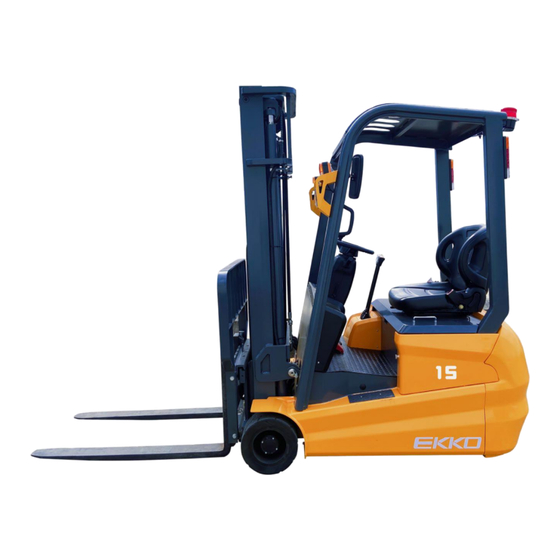
Lubrication System Diagram Main Technical Parameter of the Forklift... - Page 10 External View of the Forklift...
- Page 11 Technical Parameter...
-
Page 12: Construction, Principle, Adjustment And Maintenance Of Forklift
Construction, Principle, Adjustment and Maintenance of Forklift 1. Transmission System Model EK16A Ratio 21.378 15.8487 Wheel Dia. x Width Φ250×120 Φ300x120 Oil Volume 2.2L Gear Oil Type 85W/90 The main fulcrum of the three-point counterbalanced forklift is the mechanical gearbox (see Figure 1-1). The drive wheel is secured to the flange of the drive shaft using hub bolts and a hub nut. - Page 13 Figure 1-1 1. Cabinet 2. O-ring 3. Cover 4. Combination pad 5. Oil drain plug 6. Ball bearings 7. Output shaft assembly 8. Nut 9. Input shaft 10. Taper roller bearings 11. Adjusting the spacer 12. Adjust the spacer 13. Tapered roller bearings 14.
-
Page 14: Turn To The System
Turn to the system 1. Overview The steering system primarily consists of the steering wheel, steering shaft, steering gear, hydraulic motor, and connecting components. The steering shaft is connected to the steering gear via a universal joint, while the connecting shaft links the steering wheel to the system through another universal joint. The steering column can be adjusted to a comfortable position (as illustrated in Figure 2-1). - Page 15 Figure 2-2 1. Limit column 2. Body 3. Spool 4. Linkage axis 5. Spring 6. Connection block 7. Rotor 8. Stator 9. Valve sleeve...
-
Page 16: Hydraulic Motor Assembly
3. Hydraulic Motor Assembly The pinion is secured to the mounting seat using two ball bearings and is connected to the hydraulic motor via a key. Power from the hydraulic motor is transmitted through the pinion gear to the gearwheel, which is splined to the gear shaft. -
Page 17: Steering System Reinstallation After Inspection
4. Steering System Reinstallation After Inspection a. Smooth Operation: Turn the steering handwheel to the right and left to ensure that the steering power is smooth. b. Hydraulic Pipeline Check: Inspect the connections of the hydraulic pipeline for correctness while turning the steering handwheel right and left. -
Page 18: Electric System
Electric System 1. General Description The electric system includes the battery, drive motor, lift motor, steering motor, speed control, control switches, integrated radiator, and lighting components. The circuit diagrams of the electric system are provided below. -
Page 19: Electric Controller Assembly
2. Electric Controller Assembly The three-wheel full AC controller, manufactured by ZAPI in Italy, is designed for high reliability. This controller offers several advantages, including enhanced safety, flexibility, cost-effectiveness, and robust protection standards. -
Page 20: Instrument
3. Instrument The integrated instrument, utilizing microcomputer technology, provides real-time data display for enhanced safety and comfort for the operator. It features a low voltage warning system to protect both the battery and the vehicle. 1. Battery discharge display 2. Alphanumeric display 3. -
Page 23: Fault Diagnosis
Fault Diagnosis 1. ZAPI Controller Fault Diagnosis In the event of a forklift control system failure, the fault code will be displayed on the instrumentation. Repair personnel can use this information for fault detection. Refer to the attached "Fault Diagnosis Chart Instructions"... -
Page 24: Safety Input
Code Description 244 SOFTWARE Excessive interference on the CAN bus. ERROR 245 WRONG RAM RAM storage error. MEMORY 246 AUX DRIV.OPEN Coil on the auxiliary output circuit is not connected. 247 DATA Data acquisition is in progress; the fault will clear automatically once data retrieval ACQUISITION is complete. - Page 25 Code Description 65 MOTOR Motor temperature is too high. TEMPERATURE 66 BATTERY LOW Battery charge is low. 74 DRIVER SHORTED Contactor coil is partially shorted. 75 CONTACTOR Contactor drive circuit fault. DRIVER Accelerator/lift potentiometer is pressed, causing the signal to exceed the minimum 78 VACC NOT OK calibration value.
-
Page 26: Hydraulic System
Hydraulic System 1. Overview The hydraulic system includes the lift pump, steering pump, control valve, lift cylinder, tilt cylinder, and hydraulic lines. The oil pump, which is directly connected to the motor, supplies hydraulic oil. The control valve distributes this oil to each pump. For 2-3.5-ton forklifts, the oil tank is positioned at the rear, near the battery. -
Page 27: Pump
2. Pump The electric forklift truck is equipped with gear pumps. For the 2-3.5-ton forklift, the DSG05A18F9H1-R204C gear pump serves as the lift pump. The lift pump is powered by the lift motor. 3. Control Valve The control valve is a two-spool type and includes a four-valve housing with two spools. The relief valve features a four-valve housing secured with three bolts and nuts. - Page 28 (1) Spool Operation (using the tilt spool valve as an example) (a) Neutral Position In the neutral position, high-pressure oil from the lift pump returns to the oil tank via the mid- passage. (b) Pushing the Spool In When the spool is pushed in, it closes the mid- passage.
- Page 29 (2) Relief Valve Action An overflow valve is situated between port “HP” of the pump and low-pressure port “LP.” Oil flowing through the tilt valve acts on the different diameter areas “A” and “B.” As a result, both the check valve “K” and the tilt valve “D” are pressed down onto their valve seats.
- Page 30 (3) Action of Tilt-Lock Valve The tilt spool valve housing incorporates a tilt-lock valve designed to prevent mast vibrations caused by negative pressure in the tilt cylinder and to mitigate risks associated with improper handling of the spool. When the lift motor is not running, the mast cannot be tilted forward by pushing the tilt lever. (A) Spool Pushed In When the spool is pushed in, pressurized oil flows through port B to the tilt cylinder, activating the...
- Page 31 (4) Operation of the Control Valve The control valve is operated using valve levers. All valve levers are mounted on a shaft, which is secured to the front guard with a bracket. The levers work together to control the operation of the valve. Fig.
-
Page 32: Lifting Cylinder
4. Lifting Cylinder The single-acting type lift cylinder combines the cylinder body, piston, piston rod, cylinder cap, cylinder base, and oil seals. The bottom of the lifting cylinder is fixed to the outside bracket using a pin and bolt; the top of the cylinder (the top of the piston rod) is connected to the beam on the outside bracket. - Page 33 Cylinder Support 1. Top Rail 2. Spacer 3. Dust-Proof Ring 4. Oil Seal 5. Guide Sleeve 6. “O” Ring 7. Cylinder End 8. Steel Bearing 9. Cylinder Body 10. Piston Rod 11. Piston 12. Piston Oil Seal 13. Oil Seal 14.
- Page 34 Cut-off Valve Action There is a cut-off valve that operates when the high-pressure hose bursts for any reason, preventing the load from dropping abruptly at the bottom of the lift cylinder. The oil from the lift cylinder flows through small holes in the circumference of the cut-off valve spool, creating a pressure difference between two chambers.
-
Page 35: Flow Regulator Valve
5. Flow Regulator Valve The flow regulator valve controls the descending speed of the forklift and acts as a safeguard in the event of a high-pressure hose rupture. See picture 5-15 Working Situation of Flow Regulator Valve (see picture 5-16) The return oil from the lift cylinder enters the valve cavity “G”... -
Page 36: Tilt Cylinder
6. Tilt Cylinder The tilt cylinder is of a double-acting type. Each forklift has two tilt cylinders installed on either side of the frame with pins, while the piston rod ends are connected to the outer mast. The tilt cylinder primarily consists of a piston, piston rod, cylinder body, cylinder base, guide sleeve, and seals. The piston, welded to the piston rod, is equipped with two Yx-rings and one wear ring around its circumference. -
Page 37: Hydraulic Oil Tank
7. Hydraulic Oil Tank The hydraulic oil tank for 2-3.5t forklifts is installed on the backside of the battery group. An oil filter is located within the tank, and a returning oil filter is installed in the return oil circuit to ensure clean oil supply. 8. -
Page 38: Maintenance Of Lift Pump
9. Maintenance of Lift Pump (1) Disassembly Before disassembling the pump, place the removed parts on paper or cloth to avoid damage. (A) Hold the pump securely in a vice by lightly clamping the flange section. (B) Remove bolts 11, the pump cover 5, and the pump body 1. (C) Remove bushing 6, drive gear 2, and driven gear 3. - Page 39 (C) Front and Rear Pump Cover Inspection Replace the front and rear pump covers if the lining of the inner surface changes color (to brown) and exceeds a thickness of 150. (D) Drive Gear and Driven Gear Inspection Inspect the drive gear and driven gear from both the front and rear.
- Page 40 (3) Assembly (a) Install a new seal ring and a new check ring on the front cover of the pump. (b) Install the scale board in the groove of the front cover; ensure not to confuse the suction inlet with the oil outlet.
- Page 41 Fig.5-26 Gear pump 1. Pump body 7. Seal ring 2. Driven Gear 8. Check ring 3. Drive Gear 9. Oil seal 4. Front End Cover 10. Elastic check ring 5. Backend Cover 11.Bolts 6. Scaleboard 12. Washer...
-
Page 42: Troubleshooting
(4) Pilot Operation The pilot operation runs the oil pump to check for normal operation. Conduct the oil pump examination on the test bench and evaluate the pump on the forklift following these procedures: (If the oil pump has been disassembled and repaired due to severe damage caused by hydraulic oil, ensure that the hydraulic oil and filter are replaced before operating the pump on the forklift.) (a) Install the pump on the forklift and attach the pressure gauge to the pressure detection outlet of the selector valve. - Page 43 Malfunction Reason Repairing Method Damaged spring Replace spring Low pressure Adjust or replace overflow Damaged valve surface valve Internal oil leak Damaged valve surface Repair valve surface High pressure Jammed valve door Disassemble and clean (2) Oil Pump Problem Possible Cause Remedies Low oil level in the tank Add oil up to the specified level...
-
Page 44: Lifting System
Lifting System 1. General Description The lifting system is a two-stage design, consisting of the inner mast, outer mast, and lift bracket. 2. Inner and Outer Masts Both the inner and outer masts are welded components. The bottom of the outer mast is connected to the drive axle, while the outer mast's middle section is connected to the frame via tilt cylinders. -
Page 45: Lift Bracket
3. Lift Bracket The lift bracket moves smoothly up and down along the channel of the inner mast using main rollers. Each main roller is secured to its axis by a snap ring, and the axis is welded to the lift bracket. The side rollers are attached to the lift bracket with bolts. -
Page 46: Layout Of Rollers
4. Layout of Rollers There are two types of rollers: main rollers and side rollers. Both types are installed on the outer mast, inner mast, and lift bracket. The main rollers and side rollers work together to support longitudinal and transverse loads, allowing the inner mast and lift bracket to operate smoothly. -
Page 47: Adjust Lift Cylinder
5. Adjust Lift Cylinder The stroke of the lift cylinder must be readjusted when the lift cylinder, inner mast, or outer mast is replaced. Follow these steps: (1) Place the piston rod heads into the upper beam of the inner mast without shims. (2) Ensure that both lift cylinders operate simultaneously when the mast reaches its maximum stroke. -
Page 48: Replacing Rollers Of The Lift Bracket
(3) Tilt the mast assembly backward as the forks descend to the ground. Adjust the pulling force of the lift chains to ensure that their tightness is equal. 7. Replacing Rollers of the Lift Bracket (1) Place a tray on the forks and ensure the forklift is parked on level ground. -
Page 49: Battery Forklift Maintenance
(5) Remove the bolts that connect the lift cylinders to the bottom of the outer mast and detach the oil pipe between the two lift cylinders without losing the nipple. (6) Once the main rollers are removed from the bottom of the inner mast and the inner mast is laid down, the main rollers on the upper outer mast will become visible at the top of the inner mast. - Page 50 Sequence Period of Item Maintenance Remark Number Maintenance Steering Wheel Replace lubrication bearing 1000 hours Drive Wheel Replace lubrication bearing 1000 hours Steering Rod Replace lubrication 1000 hours Hand Brake Moving Add lubrication 200 hours Point Foot Brake Pin Add lubrication 200 hours Drive Axle Replace gear oil...
Need help?
Do you have a question about the EK16A-177 and is the answer not in the manual?
Questions and answers