Table of Contents
Advertisement
Quick Links
Advertisement
Table of Contents

Subscribe to Our Youtube Channel
Related Manuals for EKKO EK07S Series


Summary of Contents for EKKO EK07S Series
- Page 1 SERVICE MANUAL EK07S Series Counter Balanced Stacker...
-
Page 2: Table Of Contents
Maintenance List ............................. 1 Manual Overview of main components ......................2 b. Lubrication point ............................4 Check and refill hydraulic oil ........................4 d. Check the fuse ............................... 6 2. Fault Analysis ..............................6 Common Fault analysis ........................... 7 b. The fault code is displayed ........................8 3. -
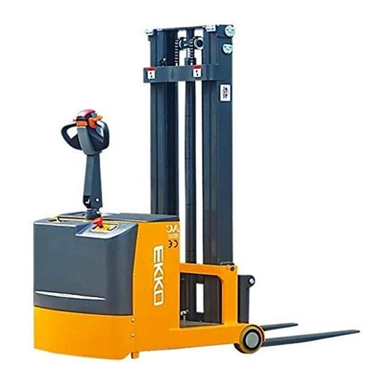
Page 3: Overview Of Main Components
1. Maintenance List Overview of main components List:1. Maintenance Lis t Interval (month) The hydraulic system 1 3 6 • Check the hydraulic cylinder, piston for damage noise and leakage • Check hydraulic fittings and tubing for damage and leakage •... - Page 4 • Check for damaged wires • Check electrical connections and terminals • Test emergency stop switch function • Check the electric drive motor for noise and damage • Detection display • Check that the correct fuse is used and replace it if necessary •...
- Page 5 • Check the air gap of the electromagnetic brake • Test emergency brake function • Test reverse braking and regenerative braking functions • Check steering function • Check lifting and descending functions • Check whether the key switch is damaged and functional •...
-
Page 6: Lubrication Point
B. lubrication points Lubricate marked points according to maintenance list. Required grease specification: DIN 51825 standard grease. Door frame track lubrication Chain lubrication... - Page 7 Axle lubrication A. Check and correct electrolytes The electrolyte density is based on 25 ℃.Therefore, when m easuring, if the tem perature of the electrolyte is higher or lower than 25℃, every 1℃ higher, should be measured from the actual density value plus 0.0007;On the contrary, lower than 25℃, every 1℃...
-
Page 8: Check The Fuse
Under the condition of normal working of charging function, the density of 1.26±0.005(25 ℃) tem perature below 30℃ sulfuric acid electrolyte into the battery, liquid level requirem ents higher than the protection plate 0.6 ~ 1.0 in. Leave the battery to rest for 3-4 hours, no more than 8 hours. -
Page 9: Fault Analysis
Fault analyses If the vehicle continues to malfunction, follow the instructions of the manual. 2.1 Common fault analysis • 2.1.1 Hand and foot brake common faults and troubleshooting methods fault cause maintenance Lift only the maximum load as Excessive cargo weight shown on the nameplate Battery discharge The battery... - Page 10 Controller damage Replacing a Controller The forklift suddenly started The accelerator has not moved back to Repair or replace the accelerator the middle position Check the battery condition on the Battery discharge discharge monitor The electromagnetic brake has been Check electromagnetic brake activated The handle wiring harness is not Check handle wiring harness and...
- Page 11 CURRENTSENSE Current detection fault 2) Electromagnetic brake drive open FAULT circuit EEPROM CHECKSUM EEPROM failure 1) Electromagnetic brake coil open FAULT HARDWARE FAILSAFE Motor voltage is out of 2) Electromagnetic brake drive short range circuit HPD FAULT HPD fault 1) Short circuit of motor or motor wiring MAIN FAULT The main contactor is 2) The controller is faulty...
- Page 12 THROTTLE FAULT Potentiometer slip end 2) Wrong adjustment of accelerator or low UNDERVOLTAGE The terminal voltage is 1) Main contactor adhesion or open FAULT out of range 一、 Methods for troubleshooting common faults 1、Code 4.5 Battery is not connected Check whether the fastening of cable terminals of the car body is loose, as shown below: Check whether the cable connection (including other secured parts) is loose 2.
- Page 13 1、Codes 3.4 and 3.2 Electromagnetic brake line problems, or electromagnetic brake failure Use a multimeter to measure the resistance of the two cores on the controller to the plug-in. The specific operations are as follows: Normally, it should be about ω.
- Page 14 Switch the multimeter to 20V DC, insert the pen j1-1 (accelerator 0-5V speed signal) and 2 (negative pole) respectively, turn the accelerator after power on, and If the voltage change of accelerator is normal, replace the controller. Six, determine the controller fault Unplug the accelerator docking plug, if the controller is still reported fault after powering on (in addition to the above faults), the controller is faulty.
- Page 15 1.Here is the coil wiring of the lifting contactor (line numbers are 2 and 15). After powering on, press the lifting button to measure whether there is a voltage of about 24V at these two places. If so, and there is no sound of pulling on the contactor, then the contactor is faulty.
- Page 16 Using an inner hexagon wrench, adjust the pressure.
-
Page 17: Schematic Diagram And Wiring Diagram
a、 Schematic diagram, and wiring diagram EK05S Electrical Schematic diagram... - Page 18 EK07S Electrical Schematic diagram...
-
Page 19: Hydraulic Circuit
B、Hydraulic circuit Hydraulic circuit... -
Page 20: C Hydraulic Oil Inspection
Hydraulic oil inspection Appearance odor condition results Clear not discoloration good good can be used check viscosity, if qualified can color transparency good with other oil mix continue to use to separate moisture or replace Color changes like milk well mixed with air and water hydraulic fluid The color becomes dark brown... - Page 21 quantit Specifi code Name Specification cation T600 T600 Dtong handle Hexagon socket head GB/T 70.1-2000 M8×20 screws GB/T93-1987 Φ8 Elastic washer GB/T95-2002 Φ8 Flat washer GB/T 95-2002 Φ10 Flat washer Q1545.07.01 Handle bar welded Composite sleeve with CL10.5-1 shoulder GB 894.1-86 Φ17 Shaft with elastic retainer Hexagon socket head...
- Page 22 B、Removal of electric control component...
-
Page 23: Removal Of Electric Control Component
Specificatio Code name B、 Removal of electric control component... - Page 24 GB982-77 Φ18 Combination gasket E05JZ-02.4.2B hose E1230X.03-5 Hollow bolt GB/T 70.1-2000 M8×20 Hexagon socket head screws GB/T 93-1987 Φ8 Elastic washer GB/T 95-2002 Φ8 Flat washer E05JZ-02.4.1 Steel pipe SPN10.8-6 The tubing connector GB982-77 φ 16 combined gasket G1/4 Explosion-proof valve SPN1030.8 Oil cylinder C、Hydraulic assembly removal...
-
Page 25: Hydraulic Assembly Removal
GB/T 41-2000 Hexagonal nut c、Hydraulic assembly removal... - Page 26 GB/T 93-1987 Φ6 Elastic washer SL20 CL 老款 Controller B+ connects to a copper bar GB/T 6170-2000 Hexagonal nut GB/T 93-1987 Φ8 Elastic washer Main contactor connecting piece ZAPI AC0 controller SW80 relay Contactor fixing plate GB/T 95-2002 Φ4 Flat washer GB/T 93-1987 Φ4 Elastic washer...
- Page 28 Quant Remark Code Name Specification...
- Page 29 E05JZ-02.1.1 The outer door frame is welded GB/T 70.1-2000 M8×20 Hexagon socket head screws GB/T 93-1987 Φ8 Elastic washer GB/T 95-2002 Φ8 Flat washer SPN10.7.1 Guide wheel shaft seat weld piece GB/T 276-94 6204 Deep groove ball bearing GB 894.1-86 Shaft with elastic retainer GB 893.1-86 Holes...
- Page 30 TY-01.35 Rz-15gw2s-b3 Microswitch (length) GB/T 70.1-2000 M6×12 Hexagon socket head screws GB/T 93-1987 Φ6 Elastic washer GB/T 97.1-2002 Φ6 Flat washer CLJ1030.06-5 Limit switch mounting plate E、Internal door frame assembly removed...
- Page 31 Specificat Quanti Code Name Remark...
- Page 32 GB/T 276-94 6204-2Z Deep groove ball bearing Φ20 GB 894.1-86 Shaft with elastic retainer Φ47 GB 893.1-86 Remar CODE NAME Specification Quantity Holes with elastic retainers SPN10.2-5 sprocket GB/T 70.1-2000 M8×25 Hexagon socket head screws GB/T 6170-2000 Hexagonal nut E05JZ-02.2.1 Inner frame welding (3 m) Hexagon socket set screws GB/T 77-2000...
- Page 33 SPN10.3-3 Lateral pressure pad SPN10.3-1 Tray rack roller Φ52 GB 893.1-86 Holes with elastic retainers Φ25 Shaft with elastic retaining ring GB 894.1-86 type A GB/T 276-94 6205-2Z Deep groove ball bearing Hexagon socket set screws GB/T 77-2000 M12×20 with flat end Shaft with elastic retaining ring GB 894.1-86 type A...
- Page 34 3. When the vehicle is running and the hand-held cursor flashes, there will be English fault content, which can be interpreted by referring to the fault code table Vehicle signal detection: 1. After connecting the handheld unit with the controller, open the key switch 2, According to the menu list of CURTIS hand held unit, find: Monitor..
- Page 35 The programmer is powered on The connection line of the handheld programmer can be connected to the controller by inserting the programming port of the controller. After connecting the controller, the handheld programmer will be powered on automatically and the control information will be displayed on the programmer.
- Page 36 The function keys Since the function of the three keys determined specified content, the three keys are blank. At any given time, the function button displayed on the LCD screen above. Direction arrow key The displayed information can be selected up, down, or left by four directional buttons.
- Page 37 The menu structure The main menu consists of nine sub-menus, and each sub-menu is displayed with a specific icon. Each item in the sub-menu is arranged by hierarchy. Some menus contain only one item of information, but most menus contain more than one item of information, and open each item folder to access the next level of sub menus.Expand the table through the grid option, enter a group of execution commands through the dialog box option, and return to the upper menu regardless of the interface by pressing the left direction button.
- Page 38 Fault Diagnosis menu On the main menu, Select Diagnostics and press Select to access the Fault diagnosis menu. The Fault diagnosis menu contains Present Errors current faults and Fault History historical faults Note: Sometimes a fault caused by a temporary event captured in the circuit is not a system fault. You can determine whether the fault exists by restarting the system and observing whether the fault disappears automatically.
Need help?
Do you have a question about the EK07S Series and is the answer not in the manual?
Questions and answers