INTEGRA Metering CALEC energy master Installation And Operating Instructions Manual
Hide thumbs
Also See for CALEC energy master:

Subscribe to Our Youtube Channel
Related Manuals for INTEGRA Metering CALEC energy master


Summary of Contents for INTEGRA Metering CALEC energy master
- Page 1 Installation and operating instructions ® CALEC energy master The benchmark for energy measurement technology Firmware Version 1.00 VD 3-137e, 08.2018...
-
Page 2: Table Of Contents
1 Contents 1 Contents 10 Mounting the device with protective housing (Prot) 2 Information and references 10.1 Scope of supply, tools and mounting 2.1 Information material (Prot) 2.2 Documents 10.2 Installation (Prot) 3 Safety notices 11 Mounting the device without protective 3.1 Symbols used housing (Mod) 3.2 Intended use... - Page 3 ® 17.1.4 M-Bus address 22 The CALEC master modules 17.2 Settings for the calculator function 22.1 The supply module 100-240 VAC 17.2.1 Standard applications 22.1.1 Safety instructions 17.2.2 Do not change settings in 22.1.2 Function and connections programming mode 22.2 The CPU module 2 x Pt100 17.2.3 How does one recognize devices 22.2.1 Function and connections with CE conformity assessment? 39...
-
Page 4: Information And References
2 Information and references Information These installation and operating instructions describe the installation and commissioning of a stan- dard device. The chapters describe the topics and tasks in the sequence in which they are needed during commissioning. • Safety instructions •... -
Page 5: Safety Notices
3 Safety notices Symbols used Important information Non-observance can lead to malfunction. General warning Non-observance can lead to damage or malfunction. Warning of dangerous electric voltage Non-observance can lead to physical injury! Intended use The device is used as an energy calculator for heating, cooling and air conditioning applications in district heating or cooling, in building management services and in industrial energy metering. -
Page 6: Installation Guidelines
Installation guidelines The installation should be performed by authorised, skilled personnel, in compliance with the regulations in force (EN1434 part 6 Regulations and recommendations for installation and operation) and the recommendations of the industry-specific associations (e.g. the AGFW series of leaflets on district heating supplies). The skilled personnel must have read and understood these instructions. -
Page 7: Pattern Approval, Versions, Marking
4 Pattern approval, versions, marking Pattern approval and conformity assessment (Prot) 4.1.1 European conformity assessment for heating applications For custody transfer, all three component parts of a combined energy calculator must have pattern approval and a conformity assessment. The device with protective housing complies with Directive 2004/22/EC (Measurement Instruments Directive, MID). -
Page 8: Short Text Calec
Marking „Prot“ected version „Mod“ule version Module Type plate On the cover On the display module Wiring diagram Inside cover Enclosed in packaging On the side of the module Terminal No. Above/below the terminals Above/below the terminals Above/below the terminals The assignment of the signals to the terminals is displayed in the operating menus, on those pages where the settings for the signals are performed. -
Page 9: View Of Device With Protective Housing
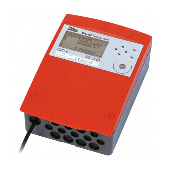
5 View of device with protective housing Device with closed protective housing 1 Housing cover 2 Operating keys 3 Dot-matrix LCD 4 Type plate with CE marking 5 IR interface on display module (EN13757-2 / -3 M-Bus) IrDA interface on CPU module 6 Housing screws, covered by security sealing caps Device with opened protective housing... -
Page 10: View Of Device Without Protective Housing (Mod)
6 View of device without protective housing (Mod) The following diagram shows the device without protective housing. 2 Operating keys 3 Display, LCD dot matrix 5 IR interface (EN13757-2 / -3 M-Bus) IrDA interface 7 Display module 8a Upper terminals, plug-in 8b Lower terminals, plug-in 9 Clip-on holder for modules The Display can be installed at a remote location e.g. -
Page 11: Mounting The Device With Protective Housing (Prot)
7 Mounting the device with protective housing (Prot) Scope of supply, tools and mounting material (Prot) Warning! Precision measuring devices! Protect against heat, humidity, dirt and vibra- tion. Only unpack the device when ready to install. Non-observance can result in dam- age or malfunction. - Page 12 1. Drill holes 2. Screw on support rail 3. Clip device onto sup- port rail Wall mounting Remove clip-on holder to get a stable support. Only mount device on a flat surface! ® CALEC energy master installation and operating instructions...
- Page 13 Wiring diagram The wiring diagram is on the in- side of the housing cover. Connecting to mains power supply 100 - 240 VAC The mains supply must be connected via a two-pole separator and be adequately protected against unauthorised interruption. The mains supply 100 - 240 VAC may Terminals L, N (supply module) only be connected to the following ter-...
- Page 14 Connecting signal cables 1. Pierce sealing membrane with en- closed awl 2. Insert cable 3. Attach cable to terminal screws according to wiring diagram on the inside cover 4. Affix strain relief clamp Closing housing 1. Insert the cover into the hinge from above and turn to close 2.
-
Page 15: Mounting The Device Without Protective Housing (Mod)
8 Mounting the device without protective housing (Mod) 8.1.1 Rail mounting 1. Drill fastening holes 2. Screw on support rail 3. Clip modules onto support rail 8.1.2 Connecting to mains power supply 230 VAC Refer to the wiring diagram before starting wiring! The mains supply may only be connected to terminals L and N! The device is fully isolated and requires no grounding connections. -
Page 16: Vdc
8.1.3 Connecting to low voltage supply 24 VDC 1. Strip cable as shown in drawing 2. Attach cable to the con- nect module (see en- closed wiring diagram) 8.1.4 Connecting signal cables 1. Attach signal cables to terminal screws accord- ing to enclosed wiring diagram 2. -
Page 17: Applications
9 Applications Applications for energy calculator 9.1.1 Overview of energy applications The wiring diagram S-EM1 on the inside of the upper section of the housing summarises all con- nection variants of the device version for heat meters. The diagram shows the standard assembly with the modules (left to right). -
Page 18: Heat Meter Application
9.1.2 Heat meter application When used as a heat meter, the transport of energy from a heat source to the consumer is meas- ured in the supply and return flow of a transport duct. This requires signals measuring the supply temperature and the return temperature, and signals from a flow sensor. -
Page 19: Cooling Meter Application
9.1.3 Cooling meter application The following characteristics differentiate the cooling meter application from the heat meter appli- cation: • The supply temperature is lower than the return temperature, i.e. Tsupply = Tc, Treturn = Th. • The temperature difference is in the range of 1 … 15 K. This means that, for the same energy consumption, the flow rate is markedly higher than in heating applications. -
Page 20: Flow Meter Application
9.1.4 Flow meter application As a flow meter/calculator, the signals from the flow sensors are converted into current values and cumulative volumes. The measured liquid is also called a ‘heat transfer medium’ in this function, although only the flow rate is measured. A flow meter can be realised in each logical calculator. -
Page 21: Mounting The Device With Protective Housing (Prot)
10 Mounting the device with protective housing (Prot) 10.1 Scope of supply, tools and mounting material (Prot) Warning! Precision measuring devices! Protect against heat, humidity, dirt and vibra- tion. Only unpack the device when ready to install. Non-observance can result in dam- age or malfunction. - Page 22 1. Drill holes 2. Screw on support rail 3. Clip device onto support rail Wall mounting Remove clip-on holder to get a stable support. Only mount device on a flat surface! ® CALEC energy master installation and operating instructions...
- Page 23 Wiring diagram The wiring diagram is on the in- side of the housing cover. Connecting to mains power supply 100 - 240 VAC The mains supply must be connected via a two-pole separator and be adequately protected against unauthorised interruption. The mains supply 100 - 240 VAC may Terminals L, N (supply module) only be connected to the following ter-...
-
Page 24: Connecting To Low Voltage Supply
1. Pierce sealing membrane with en- closed awl 2. Insert cable 3. Attach cable to terminal screws according to wiring diagram on the inside cover 4. Affix strain relief clamp Closing housing 1. Insert the cover into the hinge from above and turn to close 2. -
Page 25: Mounting The Device Without Protective Housing (Mod)
11 Mounting the device without protective housing (Mod) 11.1.1 Rail mounting 1. Drill fastening holes 2. Screw on support rail 3. Clip modules onto support rail 11.1.2 Connecting to mains power supply 230 VAC Refer to the wiring diagram before starting wiring! The mains supply may only be connected to terminals L and N! The device is fully isolated and requires no grounding connections. -
Page 26: Connecting To Low Voltage Supply
11.1.3 Connecting to low voltage supply 24 VDC 1. Strip cable as shown in drawing 2. Attach cable to the con- nect module (see en- closed wiring diagram) 11.1.4 Connecting signal cables 1. Attach signal cables to terminal screws accord- ing to enclosed wiring diagram 2. -
Page 27: Electrical Connections
12 Electrical connections 12.1 Connection instructions Devices with 100 - 240 VAC connections must have a safety fuse with a max. 10 AT, and must be capable of being made voltage-free by means of an isolating element! The device must be connected to the same electric circuit and the same fusing, switch- ing and isolating elements as the corresponding heating or cooling system. -
Page 28: Numbering Rules
12.3 Numbering rules Basic rule: The signals are numbered from right to left and from the top down. This table shows the elements that have a number, and their maximum number. Element Display/number Explanation Module Mod-No.1… 6 (Prot) * Numbers according to assembly from right to left Mod-No.1…15 (Mod) * No. -
Page 29: Commissioning A Measuring Point
13 Commissioning a measuring point An energy measuring point consists of the following peripheral equipment: • Calculator • Temperature sensor pair • Flow sensor (fm) These are matched to each other and must not be exchanged. Temperature sensors with two wires must not be shortened or lengthened. -
Page 30: Operation
14 Operation 14.1 PC-Software AMBUS Win II The parameters of the device can be set both via keys and display and via one of the data inter- faces with the PC parameterising software AMBUS Win II. With AMBUS Win II, the meter reading data can be saved, and parameter settings that have to be executed repeatedly can be stored as macros, which can then be reloaded and run. -
Page 31: Right Of Access, Security Levels
14.2.1 Key functions Keys Function in display mode Function in edit mode Move line/image up or down Setting of figures and/or characters Selection from a preset list No function in the main menu Select setting position in the edit window Change channel / input / output Change list inside a double-list Change billing date / logger period... -
Page 32: Menu Overview
15 Menu overview 15.1 Main display and main menu 15.2 Submenus ® CALEC energy master installation and operating instructions... - Page 33 ® CALEC energy master installation and operating instructions...
- Page 34 ® CALEC energy master installation and operating instructions...
-
Page 35: Use Under Operating Conditions
16 Use under operating conditions 16.1 The main display Main display After switching on the device, the page ImpVal 1.00000 L marked ‘start’ of the main display ap- Side Q cold side C.-Dat. 21.04.09 pears. Valid 31.12.13 The arrow keys can be used to move Start between a maximum of 4 pages of the main display:... -
Page 36: The Measured Values Submenu
16.2 The measured values submenu 16.2.1 Measured values Measured values Meter readings Meter readings for energy, volume (mass) Current values Current values: temperatures, volume/mass flow rates, power Billing date 1 values Meter readings on the set billing dates Billing date 2 values Logger values Meter readings per calculator at the set times 16.2.2 Meter readings... -
Page 37: Settings On Commissioning
17 Settings on commissioning 17.1 General settings The device parameters can be set with the keys. The level of protection determines which parame- ters can be changed (see section 0). On delivery, the device is in user mode. See section 10.1 on how to use the parameterisation software. -
Page 38: M-Bus Address
17.1.4 M-Bus address Addressing type, i.e. collective or single address, and the M-Bus addresses (M-Bus modules and the infrared interface according to EN60870-5) can be set in service mode M-Bus primary and secondary address under Operating mode / M-Bus addressing: Entry Parameter M-Bus Addressing 1... -
Page 39: How Does One Recognize Devices With Ce Conformity Assessment
17.2.3 How does one recognize devices with CE conformity assessment? Devices with CE conformity assessment can be recognized by: 1. the CE mark on the type plate (see section 4.1), 2. the indicated values for the calibration date and calibration validity. Go to page 1 of the main display (start window and Without conformity assessment With conformity assessment... - Page 40 Parameters for temperature sensors The following parameters are available in the Basic settings/Pt100-Input operating menu: The type of connection can be set in service mode Settable? Parameter Pt100-Input 1 Select input with the keys Mod-No. 1 Module number, here the CPU module on the right Trm.No.
-
Page 41: Time Settings: Date, Billing Dates, Logger Etc
17.2.5 Time settings: date, billing dates, logger etc. The submenu Operating setting / time settings groups various settings connected to time set- tings: Settable? Parameter Time settings Date/ti 30.06.08 12:34 etc. OK Date and time, enter character by character Bil d 1 30.06.-- Date for billing date 1 enter character by character Bil d 2 31.12.-- Date for billing date 2 enter character by character... -
Page 42: Troubleshooting
18 Troubleshooting 18.1 Messages Messages are triggered by the events set out in the following table. In case of a fault or alarm, the backlight of the display will flash, and a message will appear in the Error messages menu in the main display. The table shows triggered events, display and actions to be taken in relation to the messages: Event type Trigger... -
Page 43: Message Submenu
18.3.1 Message submenu In this submenu, all messages are displayed for approx. 5 seconds. Messages Messages Limit value Th < 50°C Display during normal operation. Example of a user-programmed message. 18.3.2 Alarm / error submenu This message is also available as a copy in the main menu (see section18.2) Alarm / Error Alarm / Error 1 No error... -
Page 44: Error Messages
The calibration log records 10 entries with a time stamp, which are relevant for maintaining metro- logical CE-conformity. Title/Number Calibration event Time stamp Note Calibration log 1 Device calibrated DD.MM.YY hh:mm Date of last ‘calibration’ By activating programming mode, the Calibration log 2 Calibration invalid DD.MM.YY hh:mm... - Page 45 Message Description/possible cause Comment/action to take module and the mains unit Check module assembly Too many modules The number of modules is too great, or Check module assembly the address assignation failed Module missing An expected module (shown in the saved Assemble module or adapt con- list) between CPU module and mains unit figuration to the existing assem-...
-
Page 46: Maintenance, Recalibration, Disposal
19 Maintenance, recalibration, disposal 19.1 Maintenance and recalibration The following components need regular maintenance: The backup battery in the CPU module must be replaced in the factory after 10 years. The contacts of the electromechanical relay in the output module 2 x 240 VAC must, depending on the load, be checked after 5-10 years and, if necessary, replaced. -
Page 47: Dimensional Drawings And Technical Specifications
20 Dimensional drawings and technical specifications 20.1 Dimensional drawings of device with protective housing Prot 20.2 Drawings of device without protective housing (Mod) ® CALEC energy master installation and operating instructions... -
Page 48: Technical Specifications
Dimensional drawings of modules with low voltage Massbilder Module mit Netzspannung In supply module 100-240 VAC and output module 2 x relays 240 VAC, the terminals are protected against accidental contact by two lateral partition walls. Dimensional drawing of display module The dimensions in the diagram refer to the size of the section. - Page 49 CPU module 2*Pt100 Energy error in % Ec <= 20 mK / ∆T (mK) Accuracy of energy calculation Significantly below EN 1434-1: Ec <= 0.5% + (∆T/∆Tmin) ∆T [K] Ec CALEC energy master Ec EN 1434-1 0.7% 1.5% 0.3% 0.07% 0.65%...
- Page 50 Temperature measurement CPU-module 2*Pt100 and Input-module 2*Pt100 Temperature range -50 … +550 °C according to MID/EN1434: 1 … 200 °C Temperature deviation < ± 10 mK Temperature differential range 0 … 550 K according to MID/EN1434: 3 … 198 K Deviation ∆T ( Ta = 5 …...
- Page 51 Output module 2*relays 24V, analogue Number of outputs Output type settable Relay functions: Pulse / status / limit value / limit value 2 Analogue functions: 0 … 20 mA / 4 … 20 mA Test functions: Relay test / analogue test Relay output (solid state relay) Max.
-
Page 52: The Module System
21 The module system 21.1 Arrangement and connection of the modules Thanks to its modular design, the device is flexible and can be adapted to different requirements. The units are fitted in the factory with the modules that were ordered. Additional modules can be retrofitted in the field, or those not needed can be removed. -
Page 53: The Calec Master Modules
® 22 The CALEC master modules 22.1 The supply module 100-240 VAC 22.1.1 Safety instructions The terminals are protected against accidental contact by lateral partition walls. This also prevents the mixing up of terminals for mains and low voltage supplies. Caution: dangerous electric voltage! Misuse can lead to physical injury! The input cable must be protected with an external fuse F<10 AT. -
Page 54: The Cpu Module 2 X Pt100
22.2 The CPU module 2 x Pt100 22.2.1 Function and connections Signal and terminal assignments: Upper terminals (5 - 1 - 2 - 6): Pt100-input 1 Temperature hot side Lower terminals (7 - 3 - 4 - 8): Pt100-input 2 Temperature cold side The CPU module with the central processor for the calculating, control and memory functions has the following features:... -
Page 55: Ordering A Cpu Module As Spare
22.2.3 Ordering a CPU module as spare When ordering a CPU module as spare, please order the version that corresponds to the device con- cerned. The corresponding module can be distinguished by its desiganation as shown in the example below: Device designation CPU-Module designation EM-101-Prot-AC[...I]C-T... -
Page 56: The Display Module
22.3 The display module 22.3.1 Function The display module can be fitted on the CPU module or mounted separately with the RDA set, e.g. on a control panel. The display module consists of: • A dot-matrix display (128 * 64 pixel) with a white backlight. In case of a device fault or alarm, the backlight flashes red. -
Page 57: The Input Module 2X Pulse/Analogue
22.4 The input module 2x pulse/analogue 22.4.1 Function and connections Signal and terminal assignments Upper terminal row Active transmitter: 10 - 11 Passive transmitter: 82 -10 Lower terminal row: Active transmitter: 56 - 57 Passive transmitter: 83 - 56 The input signals are numbered - from right to left - from top to bottom The module has two universal inputs e.g. -
Page 58: Settings
22.4.2 Settings The parameters of the inputs can only be set in programming mode. In EC conformity assessed devices, changes will invalidate the calibration! The settings for input signals in the basic setting / input submenu differ, depending on type of signal. The values can be divided into three groups: Main parameters Input 1... -
Page 59: Digital Signal Types
22.4.4 Digital signal types Most signal transmitters can be used with the signal types IB… IE and PFM: Transmitter types ID (Namur) Potential free contact, Reed possible Open collector up to 200 Hz Open collector up to 10 kHz NAMUR up to 200 Hz NAMUR up to 10 kHz Kamstrup 'slow' For the above-cited signal types, the input signals must meet the following requirements:... - Page 60 Digital signal ‘pulse’ function The pulse function allows metering via a pulse signal Input 1 Select the input with the keys … Signal ID Namur 200Hz Signal type e.g. Class ID Namur 200Hz acc. to EN 1434 Funct. Pulse Pulse function metering using pulse signals as input MeaVar Volume Physical quantity...
-
Page 61: Units Of The Pulse Function
22.4.6 Units of the pulse function The unit of the output pulse value depends on the unit of the corresponding meter. If, for instance, an energy meter reading in kWh is connected with a pulse output signal, the unit of the pulse value is Wh/pulse. The table shows the relationships: Meter Unit... -
Page 62: Special' Signal Type
22.4.8 ‘Special’ signal type The signal type ‘Special’ allows: • inputting constant, virtual input variables, e.g. a reference temperature • adapting the electrical characteristics of the input switch for special signals The table shows the settable parameters: Input 2 keys Select the input with the …... -
Page 63: The M-Bus Module
22.5 The M-Bus module 22.5.1 Function and connections The M-Bus module can communicate as an M-Bus slave with an M-Bus master via an M-Bus network according to EN 1434-3 (Single Master Bus). Up to two M-Bus modules can be operated per device. The M-Bus interface can be used for remote reading of the data or for setting the device parameters. -
Page 64: Other Settings
22.5.3 Other settings For each M-Bus module, service mode can be used to set the M-Bus interface parameters in the menu Operating settings / interface: Settable? Parameter Interface 4 Select interface 4 and 5 with the keys Mod-No. 3 Module number, displayed automatically T-No. -
Page 65: Ec Declaration Of Conformity
23 Declaration of conformity ® CALEC energy master installation and operating instructions... -
Page 66: Terms
24 Appendix 24.1 Terms, abbreviations, formula symbols 24.1.1 Terms Term Meaning Installation side Density and specific heat capaicity are functions of temperature. It is therefore of sig- nificance for the calculation which temperature measuring value is used. The installa- tion side (hot or cold side) determines this. Paired temperature Two temperature sensors are selected during production in such a way that the meas- sensors... -
Page 67: Appendix
Abbreviation Meaning Lco T Cut-off at small temperature difference. Can be activated to suppress energy measure- ment during irregular system statuses (e.g. gravitational circulation when pump is switched off) Lco Q Low flow cut-off Status signal pulse input TWIN-E Measurement in open systems with 2 flow sensors. Used where heat transfer medium be- tween forward and return pipe is removed from the system TWIN-V Flow measurement with 2 parallel fitted flow sensors, e.g.
Need help?
Do you have a question about the CALEC energy master and is the answer not in the manual?
Questions and answers