
Subscribe to Our Youtube Channel
Related Manuals for INTEGRA Metering CALEC ST III


Summary of Contents for INTEGRA Metering CALEC ST III
- Page 1 CALEC® ST III Standard & Smart Multi-protocol heating and cooling energy calculator User manual 3-140-UM-EN-02 1 / 56...
- Page 2 First release Connection of 2-wire temperature sensor updated 04/27/2021 Menu structure extended by LON and KNX Technical data updated Original instructions Publisher INTEGRA Metering AG Ringstrasse 75 CH-4106 Therwil Switzerland Phone: +41 61 725 11 22 info@integra-metering.com www.integra-metering.com Reproduction of these instructions or parts of them in whatever form is not permitted without express writ- ten permission from the publisher.
-
Page 3: Table Of Contents
Table of contents Table of contents Introduction........................... 6 About this product .............................. 6 1.1.1 Product description .............................. 6 1.1.2 Product identification.............................. 6 1.1.3 Technical data ................................ 7 1.1.4 Conformity................................... 11 1.1.5 Declaration of conformity............................ 12 About the instructions ............................... 12 1.2.1 Purpose of this instruction ............................ 12 1.2.2 Structure of overall documentation ........................... - Page 4 Table of contents 6.1.1 Display .................................. 37 6.1.2 Buttons.................................. 37 Switching on the meter ............................. 38 Navigating through the menus.......................... 39 Editing parameter values ............................ 39 Entering the service mode ............................ 40 Menu structure ................................ 41 6.6.1 Counter .................................. 41 6.6.2 Info ..................................... 41 6.6.3 Test.....................................
- Page 5 Table of contents Decommissioning .............................. 54 Storage .................................. 54 Disposal .................................. 54 Appendix ............................. 55 Drilling template................................. 55 3-140-UM-EN-02 5 / 56...
-
Page 6: Introduction
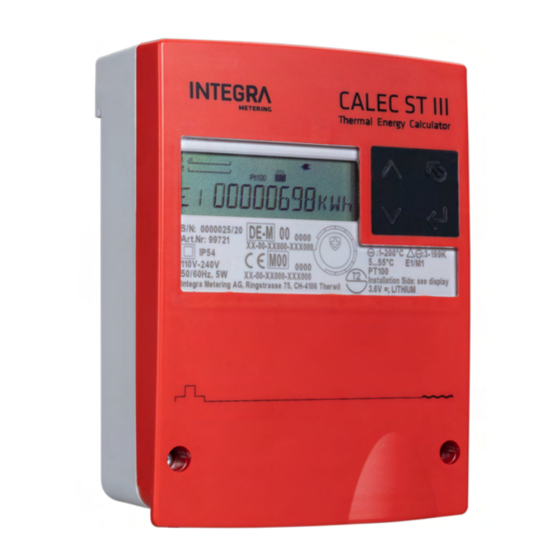
Introduction Introduction About this product 1.1.1 Product description CALEC® ST III is an energy meter used in the areas of: commercial buildings / building technology near and district heating / district cooling residential construction / sanitary The main applications of the product are: System integration component With the versatile interfaces of CALEC®... -
Page 7: Technical Data
Introduction 1.1.3 Technical data Housing and operating conditions Dimension Ambient temperature +5 ... +55 °C, EN 1434 class C Storage temperature 0...60 °C Humidity Max. 95 % Operating altitude Up to 2000 m above sea level Protection class IP54 according to EN 60529 Signal connection: 1.5 mm screw terminals Terminals Power connection: 2.5 mm... - Page 8 Introduction Basic data for calculator Better than those required for calculators in accordance with Error limits EN 1434-1. Suitable for combined class 2 heat meters in accordance with EN 1434-1 when used with suitable volume metering units NFC interface For commissioning / parametrization: 13.56 MHz Bluetooth interface For commissioning / parametrization: 2.4 GHz Display...
- Page 9 Introduction Additional functions This option allows the management of up to eight different tariffs Heat- / cold meters eight tariffs with reference temperature control. The measurement is split into different registers. Data backup in the event of a In EERPOM >10 years power failure Adjustable low temperature differ- Function for stopping the energy calculation when the temperature...
- Page 10 Introduction Pulse inputs 2-wire pulse input according to class ID compliant with EN1434-2 Suitable for NAMUR-, “Open Collector” or mechanical pulse sources Supply voltage 8…8.4 V Source impedance 1 kΩ Switching threshold IL 2.1 mA Pulse input class ID Switching threshold IH 1.2 mA Pulse length ≥...
-
Page 11: Conformity
Introduction N2Open (option) Physical layer and address RS 485 / address: 1…255 / Default: 1 Baud rate 9’600 Baud 2 analog outputs (option) Output signal 4...20 mA or 0...20 mA Supply voltage 6...24 VDC Electrical isolation max. 48 VDC Maximum resistance ≤ 837 Ω at 24 VDC, 0 Ω at 6 V Maximum transformer error 0.15 % of measured value + 0.15 % of end value KNX (option) -
Page 12: Declaration Of Conformity
Introduction Standards EN 61326-1 EN 62479 EN 300 220-2:V3.1.1 EN 300 330:V2.1.1 EN 300 328:V2.1.1 Specific PTB K7.2, Ordonnance of FDJP 941.231 (CH), Welmec 7.2, OIML D11 1.1.5 Declaration of conformity The declaration of conformity is available by scan- ning the QR-Code. About the instructions 1.2.1 Purpose of this instruction... -
Page 13: Safety
Safety Safety Explanation of warning notices DANGER Danger This safety warning indicates a hazard of high risk that will lead to serious physical injury or death. Measures to avoid the hazard. WARNING Warning This safety warning indicates a hazard of medium risk that may lead to serious injury or death. -
Page 14: Technical Condition Of The Product
Safety Technical condition of the product Spare parts Replace defective parts only with original spare parts from INTEGRA Metering. Software The software must not be modified. Backfitting The product must not be backfitted. Changes of the operating mode must be agreed in writing with the manufacturer. -
Page 15: Product View
Product view Product view Product design Front cover 2 Connection diagram (inside of front cover) 3 Pluggable calculator 4 Motherboard with connection 5 Clip-on holder for top-hat rail Functional description A heat or cooling meter is composed of the following individually approved sub-assemblies: Energy calculator Temperature sensor for forward... -
Page 16: Calibration And Verification
Product view Temperature measurement The CALEC® ST III is fitted with two highly accurate temperature measurement inputs. They are each con- nected to type-approved, paired temperature sensors in two- or four-wire configuration. The planning of systems should conform to heat meter standard EN 1434, parts 2 and 6. EN 1434-4 stipulates that only sen- sors of the same design and length should be paired together. - Page 17 Product view – 2× extension slots for adding options: KNX, LON, Wireless LoRa, 2AOU 2× inputs for temperature 2 / 4-wires (PT100 / 500 / 1000) 2× master inputs (volume / status) – On the second input, pulse, volume, mass, energy, status and alarm can be selected as input. –...
-
Page 18: Transport / Scope Of Delivery
In case of externally visible transport damage, proceed as follows: Do not accept delivery or accept it under reserve. Note the extent of damage on the transport documents or on the delivery note of the carrier. Report any damage to INTEGRA Metering immediately. 18 / 56 3-140-UM-EN-02... -
Page 19: Installation
Installation Installation CALEC® ST III can be installed on a flat wall or on a mounting rail. Suitable mounting rails are available as ac- cessories. Conditions Meet the following conditions according to the specifications in the Technical data to ensure a reliable operation. -
Page 20: Installation On A Wall
Installation 5.2.1 Installation on a wall Tools and installation material are not included in the delivery. Flat screwdriver 3.5×0.6 Torx screwdriver TORX T15 Drill bit Ø6 Screws 3×Ø4 Dowels 3×Ø6 Washers 3×4.3×12 Take off the front cover Remove the two screws (1). Remove the cover (2). -
Page 21: Installation On A Rail Din En 50222
Installation Close the front cover Fit and close the cover (1). Tighten two screws (2). Remove the safety caps (3) from the top of the housing. Attach them to each screw with the smooth side facing outwards. 5.2.2 Installation on a rail DIN EN 50222 Tools and installation material are not included in the delivery. - Page 22 Installation Clip and fix the CALEC® ST III (1) on the rail (2). Push up the clip-on holder (3). 22 / 56 3-140-UM-EN-02...
-
Page 23: Electrical Installation
Installation Electrical installation DANGER Electric shock Touching energized system parts can cause immediate death or serious injury. Make sure that installation work is only carried out by authorized specialists. Before carrying out any work on the system, disconnect the power supply and check that no voltage is present. -
Page 24: Connecting The Calec® St Iii Standard
Installation 5.3.1 Connecting the CALEC® ST III Standard NOTICE Wrong connections may destroy the device The function and the marking of the terminals A11/B11 and A12/B12 depends on the options installed in the device. Carefully check the installed options and choose the correct connections. NOTICE Incomplete wiring of the temperature sensors Incomplete wiring of the 2-wire temperature sensors may lead to false measurement results. -
Page 25: Connecting The Calec® St Iii Smart
Installation 5.3.2 Connecting the CALEC® ST III Smart NOTICE Wrong connections may destroy the device The function and the marking of the terminals A11/B11, A12/B12, A31/B31, A41/B41, A21/B21, A22/B22 depends on the options installed in the device. Carefully check the installed options and choose the correct connections. NOTICE Incomplete wiring of the temperature sensors Incomplete wiring of the 2-wire temperature sensors may lead to false measurement results. -
Page 26: Connecting 2-Wire Temperature Sensors
Installation 5.3.3 Connecting 2-wire temperature sensors NOTICE Incomplete wiring of the temperature sensors Incomplete wiring of the 2-wire temperature sensors may lead to false measurement results. Always connect the 2-wire temperature sensors together with the four supplied wire bridges. Disconnect the CALEC® ST III from the power supply. -
Page 27: Connecting Flow Meters Without Power Supply
Installation 5.3.5 Connecting flow meters without power supply Disconnect the CALEC® ST III from the power supply. Take off the front cover [}p. 20]. Connect cable (1) to terminal 10. Connect cable (2) to terminal 11. Close the front cover [}p. 20]. 5.3.6 Connecting flow meters with a 3.6 V power supply Disconnect the CALEC®... -
Page 28: Connecting Flow Meters With A 24 V Power Supply
Installation 5.3.7 Connecting flow meters with a 24 V power supply This option is only for CALEC® ST III Smart. Disconnect the CALEC® ST III from the power supply. Take off the front cover [}p. 20]. Connect the green pulse/status output common cable (1) to terminal 11 (-). Connect the yellow pulse output cable (2) to ter- minal 10 (S). -
Page 29: Connecting Flow Meters With Two Groundings
Installation 5.3.9 Connecting flow meters with two groundings This option is only for CALEC® ST III Standard. NOTICE Wrong supply voltage Wrong supply voltage may damage the adapter module. Only use 24 VDC as supply voltage. Disconnect CALEC® ST III from power supply. Take off the front cover [}p. 20]. -
Page 30: Connecting The M-Bus (Wired And Wireless)
Installation 5.3.11 Connecting the M-Bus (wired and wireless) CALEC® ST III is equipped with an M-Bus interface allowing radio remote reading and connection the M-Bus system. Wired Disconnect the CALEC® ST III from the power supply. Take off the front cover [}p. 20]. Connect M-Bus to terminals 24 and 25. -
Page 31: Connecting The Communication Modules
Installation 5.3.12 Connecting the communication modules M-Bus Additional M-Bus modules can be inserted in the CALEC® ST III in order to duplicate network or to manage several data flow for different solutions. Module #1: A11/B11 (Channel #1) Module #2: A21/B21 (Channel #1) Analogue outputs are electrically isolated The use of primary and secondary addresses is possible Setting the baud rate is possible... - Page 32 Installation BACnet Module #1: A11/B11 (Channel #1) Module #2: A21/B21 (Channel #1) The interface is electrically isolated. When installing CALEC® ST III at the end of the BACnet segment the internal termination resistor can be used. Factory settings: Manufacturer ID: 431 BACnet device profile: B-ASC BACnet MAC address: Last 2 digits of the serial number Device instance number: Last 5 digits of the serial number...
- Page 33 Installation Module #1: A11/B11 (Channel #1) Module #2: A21/B21 (Channel #1) The service PIN and the Wink LED are available for identification on the LON network. The service LED provides information about the system condition. Possibly non-poled Disconnect the CALEC® ST III from the power supply.
- Page 34 Installation Module #2 Factory settings: Frequency: 868 MHz Gain: 0 db Impedance: 50 Ω Antenna connector: SMA connector Disconnect the CALEC® ST III from the power supply. Take off the front cover [}p. 20]. Connect the antenna (0 db gain, 50 Ω imped- ance) to the SMA socket. Tighten the antenna with max.
- Page 35 Installation Module #1: A11/B11 (Channel #1) Module #2: A21/B21 (Channel #1) Module #1: A12/B12 (Channel #2) Module #2: A22/B22 (Channel #2) Module specifications: Current range: 4…20 mA / 0…20 mA Supply voltage: 6…24 VDC Electronical isolation max.: 48 VDC Resistance ≤ 837 Ω / 24 VDC Disconnect the CALEC®...
-
Page 36: Operation
Operation Operation DANGER Electric shock Touching energized system parts can cause immediate death or serious injury. Make sure that installation work is only carried out by authorized specialists. Before carrying out any work on the system, disconnect the power supply and check that no voltage is present. -
Page 37: Display
Operation 6.1.1 Display Heating circuit Flow display channel #1 Cooling circuit Flow display channel #2 External power supply OK Limit value Low battery Memory no. / channel no. Edit – esc. Tariff Edit – OK Edit – mode Memory value Wireless connected Wired connected Closed: User mode... -
Page 38: Switching On The Meter
Operation Switching on the meter Check the electrical connections. Turn on the power supply. If required, fix alarm. Check the pulse value (Imp) of the flow meter. Check the installation side (Sid) of the flow me- ter. Fit and close the cover (1). Tighten two screws (2). -
Page 39: Navigating Through The Menus
Operation Navigating through the menus Press the UP and DOWN keys to step through the main menu entries. Press ENTER to enter a sub-menu. Press the UP and DOWN keys to step through the sub-menu entries. Press ESC to exit from any menu or sub-menu. Editing parameter values Navigate to the parameter to be edited (e.g. -
Page 40: Entering The Service Mode
Operation Entering the service mode Press the DOWN key until «CONFIG» is dis- played. E1, V1 E2, V2 ..Sid Press ENTER to enter the «CONFIG» sub-menu. Press ENTER. Enter the service code «00001111». CONFIG w The service mode is unlocked and data can be edited. -
Page 41: Menu Structure
Operation Menu structure 6.6.1 Counter The depiction of fields in the menu structure depends on the respective options. Display Meaning Visible Editable Energy meter reading According to calculator function Programming mode Volume meter reading According to calculator function Programming mode Mass meter reading (op- According to calculator function Programming mode... -
Page 42: Time
Operation Display Meaning Visible Editable Temperature difference According to calculator function Performance According to calculator function Flow According to calculator function Mass flow According to calculator function Specific heat factor According to calculator function Density According to calculator function Performance 2 According to calculator function Flow 2 According to calculator function... -
Page 43: Logger
Operation 6.6.7 Logger Display Meaning Visible Editable Logger number (1…500) Yes for selection Memory interval Service mode Saving date Saving time Energy meter reading According to calculator function Volume meter reading According to calculator function Mass meter reading According to calculator function Energy meter reading 2 in op- According to calculator function tions BDE / BDV... -
Page 44: Outputs
Operation Display Meaning Visible Editable Threshold for return temper- ature in option TGR According to calculator function Programming mode Overstepping: register E2 Un- dercutting: register E3 6.6.9 Outputs This menu is only available if the output hardware module is installed in the device. Display Meaning Visible... -
Page 45: M-Bus
Operation Display Meaning Visible Editable Number of decimal places for Programming mode mass unit Power unit Service mode Volume flow unit Service mode Temperature unit Service mode Pulse value for energy pulse Service mode output Pulse value for volume pulse Service mode output Pulse value for mass unit... -
Page 46: Lon
Operation Display Meaning Visible Editable Turn termination resistor Service mode on / off 6.6.16 On the CALEC ST® III, no specific menu is available for the LON hardware. All parameters are set directly through the protocol interface itself. 6.6.17 On the CALEC® ST III, no specific menu is available for the KNX hardware. All parameters are set directly through the protocol interface itself. -
Page 47: System
Operation Display Meaning Visible Editable Automatic sensor adjust- Programming mode ment 6.6.20 System Display Meaning Visible Editable Serial number Calculator function Manufacturing date Firmware version of calcula- Firmware version of main board Hardware version Checksum of firmware 6.6.21 Init One-time on-site setting of the calibration-relevant input values “IMP EBS“ Assure that with the selected unit the accumulative energy amount can be handled without counter overflow. -
Page 48: Additional Functions
Operation Additional functions 6.8.1 Billing date values With the 12 freely programmable billing date values, the indexes can be memorized (e.g. monthly) for de- fined dates and consulted at any time [}p. 42]. 6.8.2 Data logging The CALEC® ST III can record up to 500 data records in a ring buffer at intervals of minutes, hours, days, weeks, months [}p. 43]. -
Page 49: Solar-Powered Thermal Systems
Operation Medium Display Concentra- Temperature Manufac- Type Application / observa- tion range turer tion Confirms to DIN 4757-1; toxicity class 4. For cooling, solar, Antifrogen N AntifroN 20-60% -120°C Clariant heating and heat pump systems. Low viscosity. Not harmful to health. Antifrogen L AntifroL 20-60% -120°C... -
Page 50: Pc Software Ambus® Win Commissioning
Operation Smart Phone commissioning Operating system Android >6.0; available on Play Store ParamApp Features Commissioning and readout via NFC and Bluetooth interface for better usability Download the ParamApp to a compatible An- droid device. Start up the product an run the configuration as required. -
Page 51: Maintenance
Maintenance Maintenance Calibration Devices in commercial use: All calibration-relevant functions are located on the pluggable calculator module. Device-specific settings are stored redundantly in the lower housing part. Disassembling the lower housing part with field wiring is not required for calibration. Perform a periodic recalibration according to national calibration law. -
Page 52: Service And Repairs
Service and repairs Service and repairs DANGER Electric shock Touching energized system parts can cause immediate death or serious injury. Make sure that installation work is only carried out by authorized specialists. Before carrying out any work on the system, disconnect the power supply and check that no voltage is present. - Page 53 Service and repairs Message Error/ alarm Possible cause Corrective measures Temperature on the hot side th-ALArM is outside the permitted Temperature of the heat Check the current temper- measuring range cycle is too high ature in the InStAnt sub- Temperature of the heat Temperature on the cold side menu.
-
Page 54: Decommissioning / Storage / Disposal
Decommissioning / storage / disposal Decommissioning / storage / disposal Decommissioning Disconnect the device from all sources of energy. Remove the device from the system. Storage Decommissioning according to chapter Decommissioning. Select a suitable storage location. Disposal INTEGRA products must be disposed of in accordance with applicable local regulations. Improper disposal can have harmful effects on the environment and health. - Page 55 Appendix Appendix Drilling template 3-140-UM-EN-02 55 / 56...
- Page 56 Your service partner...
Need help?
Do you have a question about the CALEC ST III and is the answer not in the manual?
Questions and answers